Abstract
The demand for simulation-based skills training in orthopaedics is steadily growing. Wire navigation, or the ability to use 2D images to place an implant through a specified path in bone, is an area of training that has been difficult to simulate given its reliance on radiation based fluoroscopy. Our group previously presented on the development of a wire navigation simulator for a hip fracture module. In this paper, we present a new methodology for extending the simulator to other surgical applications of wire navigation. As an example, this paper focuses on the development of an iliosacral wire navigation simulator. We define three criteria that must be met to adapt the underlying technology to new areas of wire navigation; surgical working volume, system precision, and tactile feedback. The hypothesis being that techniques which fall within the surgical working volume of the simulator, demand a precision less than or equal to what the simulator can provide, and that require the tactile feedback offered through simulated bone can be adopted into the wire navigation module and accepted as a valid simulator for the surgeons using it. Using these design parameters, the simulator was successfully configured to simulate the task of drilling a wire for an iliosacral screw. Residents at the University of Iowa successfully used this new module with minimal technical errors during use.
INTRODUCTION
Over the past two decades, the demand for simulation-based surgical skills training in orthopaedics has steadily grown. This demand has been driven by numerous factors. In 2003, work hour limits for residents were implemented, creating a safer work environment for employees and patients, but potentially limiting the amount of surgical experience a resident can gain during their time as a trainee [1]. In July 2013, the American Board of Orthopaedic Surgery, the body responsible for certifying orthopaedic surgeons as competent to practice, required residency programs to dedicate time and space to training first year residents for “skills used in the initial management of injured patients and basic operative skills to prepare residents to participate in surgical procedures” [2]. Some countries have even begun transitioning to a competency-based training program that advances residents when they demonstrate adequate surgical skills on various simulated tasks [3].
As simulation in orthopaedics has become more common, the number of tools available to train surgeons has steadily increased. However, a majority of the simulators available to programs today focus on a narrow range of topics, mainly those involved in arthroscopic surgery [4–6]. One task that has been difficult to train residents on in a safe and cost-effective manner is wire navigation, an orthopaedic surgical skill used in many surgical procedures. This skill enables surgeons to drill a surgical wire, typically a long, small diameter steel pin, along a specified path through bone, visualized using 2D intra-operative fluoroscopic images. Wire navigation requires sophisticated visuospatial cognitive skills because the surgeon must visualize and navigate the patients’ anatomy. In some situations, placing the wire is the final task; in others the wire serves as a guide for subsequently placed cannulated implants. Regardless of the situation, the placement of the wire in the bone directly influences the surgical result for the patient. To highlight the importance of this skill in the field of orthopaedics, the American Board of Orthopaedic Surgery includes wire navigation as one of the core competency skills [7].
Our team previously presented the design of a wire navigation surgical simulator dedicated specifically to hip wire navigation [8]. Hip wire navigation was chosen as an initial application because of the many incidences of hip fractures in the US each year [9]. However, many other surgical procedures, including some outside of orthopaedics, rely on wire navigation. Because the visualization challenges faced by the surgeon are largely task-specific, training for many of these procedures requires dedicated simulators. Instead, we have modified the existing simulator to accommodate new surgical procedures, while still exercising the underlying skill of wire navigation. This paper will explore the criteria used to develop new simulator applications, introduce an example of developing a new application, and present data from orthopaedic residents who trained with the new application.
METHODS
The simulation platform
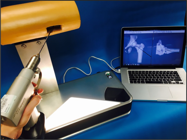
The wire navigation simulator is an optical system that uses image processing algorithms to track the position of the surgical instrument, in this case a guide wire, relative to a fixed artificial bone (Figure 1). A stereo camera system feeds image pairs to a repository on a connected laptop. When a resident requests a fluoroscopic image, the latest image pair is pulled from the repository and processed. The cameras are fixed in space, so the guide wire trajectory can be calculated in 3D space from any stereo image pair. A parallel line pattern etched around the circumference of the wire allows the algorithm to estimate the axial position of the wire. From these two pieces of information, the wire trajectory vector and the axial position, a simulated fluoroscopic image can be rendered. A foam shell encases the artificial bone that is mounted on the simulator, thus obstructing the bone geometry from the surgeon. This forces the trainee to focus primarily on the simulated fluoroscopic images when navigating the wire, as is the case in the operating room. Residents use the same drill to drive the pin into the artificial bone as they would use with a real patient in the operating room.
Figure 1.
A surgical wire drills into a plastic bone located just inside the opening in the tan, soft-tissue covering. The bone is mounted on the wire navigation simulator. A laptop displays artificial fluoroscope images used for training hip wire navigation. A camera system inside the simulator tracks the wire relative to the fixed bone to create artificial fluoroscopic images showing the wire position in bone.
Criteria for Developing New Applications
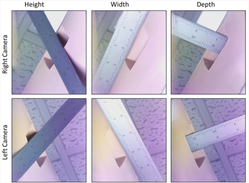
Expanding the simulator platform to simulate other surgical procedures involves comparing the capabilities of the simulator’s optical system with the needs of a specific application. The guide wire or other surgical instrument must be viewed and focused in both camera views. The overlapping, in-focus region is called the working volume. Currently, the simulator has a frustum-shaped working volume that expands out from the entry location on the surface of the artificial bone. The frustum has a width of approximately 102 mm (4 inches) at the surface of the soft tissue envelope, a depth of approximately 76 mm (3 inches), and a height of approximately 102 mm (4 inches) (Figure 2).
Figure 2.
The dimensions of the working volume are shown here. The ruler is positioned against the soft tissue which encloses the bone of the simulator. The space beyond the soft tissue defines the region of the image in which the wire can be seen by the camera system to calculate the wire position in bone.
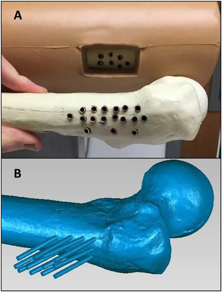
A second optical system characteristic is the precision with which the wire can be tracked. Some procedures may require more precise tracking than others. For example, the placement of a surgical wire in a pediatric elbow requires greater precision than in an adult hip because of substantial differences in the sizes of the pediatric elbow and the adult hip. Also, more advanced surgeons may be sensitive to minor position adjustments; so different types of users may require different levels of performance. To quantify the simulator’s accuracy, we compared known wire locations with the locations calculated by the optical system. The reference wire locations were defined by pre-drilled holes in two target bones. The holes were placed so that the trajectories of wires placed in the holes spanned the simulator working volume. Copper tube liners with an inner diameter matching the test wire outer diameter were placed in each hole to ensure that repeated wire insertions would not alter the hole dimensions. The copper tubes were plugged at their bottom with a metal stopper to ensure repeatable wire insertion depth (Figure 3).
Figure 3.
(A) The copper tubes used to create reproducible wire positions are shown here. The tubes are cemented in bone to create a reproducible slot that a wire can be inserted to for testing. (B) A laser scan of one of the bones with the wire positions for each slot. The laser scan defined the wire trajectory and position for each copper tube.
A laser scan of the simulator-mounted bone was acquired using a FaroArm laser scanner (FARO LLC). This defined the 3D location of each wire relative to the simulator frame (Figure 3). The FaroArm has a scanning precision of 0.024 mm (0.00094 inches) [10]. A short wire of a known length was placed into each lined hole and individually scanned to create a dataset of reference trajectories and tip positions for each prepared hole. These 29 reference positions were then compared with the associated wire trajectories and axial positions calculated by the optical system. Ten optical measurements were taken for each reference position. Because the system is sensitive to background light and image noise, this test was done in an ideal laboratory setting, as well as at 4 other locations selected as being typical for standard operation.
A third consideration to be evaluated when expanding the system to other wire navigation applications is the tactile feedback the user experiences when drilling into high density cortical tissue on the bone’s exterior versus the soft cancellous tissue in the bone’s interior. Oftentimes, detecting the transition from cortical to cancellous drilling is an important component of a surgical task. For example, surgeons often use this transition as a cue to know that the wire has passed through the bone and is at the cortical wall on the opposite surface.
The first new wire navigation application was selected in consultation with a team of orthopaedic surgeons. Together we developed a list of potential wire navigation procedures, including iliosacral screw fixation, distal radius fracture fixation, the fixing of pediatric elbow fractures, the placing of pedicle screws for spinal fusion, fixing proximal humerus fractures, and tibial plateau fractures. The iliosacral screw fixation procedure was selected because it was similar in scale to the hip wire procedure (but it demands higher precision from the trainee), it introduces imaging projections that are not orthogonal to the floor (demands a deeper geometric understanding), and because we believed that the residents would be excited to try this challenging, yet relatively rare procedure [11]. In addition, there isn’t currently a widely-adopted model for training residents on this task. A group out of the Orlando Regional Medical Center published on using a Sawbones pelvis model with a C-arm (the machine that generates fluoroscopic images) to train residents [12]. However, access to a C-arm can be limited and expensive, not to mention the exposure to radiation presents a hazard of training. Other current options for training residents on this task include cadaveric training, which can often be very expensive and would also include the use of a C-arm and radiation exposure [13].
Iliosacral Screw Fixation
The surgical technique for iliosacral screw fixation is a minimally invasive procedure that involves placing a guide wire perpendicular to the sacroiliac (SI) joint and beyond the midline of the sacral body [14]. There are several factors that make this surgically challenging. First, the corridor for placing the implant properly can be quite narrow. The corridor is surrounded by several vulnerable nerve roots and the spinal cord. Improper placement of the implant has been reported to be between 18 to 24% [15–18]. Also, pelvis anatomy is highly variable between patients, requiring the surgeon to adjust the trajectory from patient to patient and even rejecting some patients for the procedure.
A literature search revealed the parameters for ideal implant position within the anatomic variability typically encountered by surgeons. One study analyzed a set of pelvic scans to define an ideal path and acceptable corridor parameters relative to the anatomic variability [19]. This analysis defined the working volume as a cylindrical corridor through the sacral body that does not intersect with the nerve roots. The analysis indicated that across multiple pelvic anatomies, this corridor has an average diameter of 14 mm (0.55 inches) and an average length of 150 mm (5.91 inches) [19].
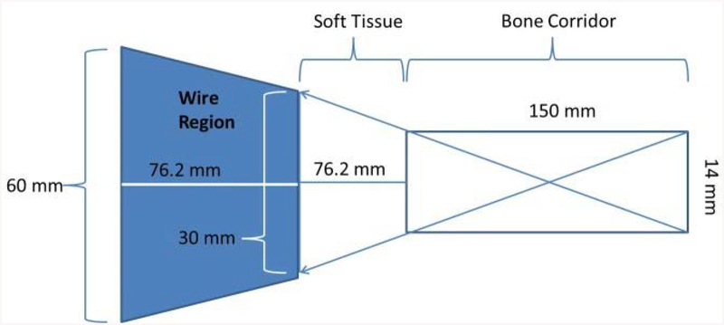
This corridor defines the wire position within the bone, but the surgeon must also guide the wire percutaneously through the surrounding soft tissue. Therefore, to fully define the working volume for this procedure, the path of the wire taken through the soft tissue to reach the bone surface must also be considered. For our implementation, we designed a soft tissue envelope with roughly 76 mm (3 inches) of material separating the surface of the bone from the area of wire visible to the camera. The resulting space occupied by the wire to reach this corridor in bone is then a frustum with a front width of 30 mm (1.18 inches), a depth of 76.2 mm (3 inches), and a back-end width of approximately 60 mm (2.36 inches) (Figure 4). This working volume allows the system to accurately track any wire that is within the safe corridor through the sacral body.
Figure 4.
This shows the potential working volume for the iliosacral screw placement on the simulator. The area in dark blue defines the potential wire regions that would be used to successfully guide a wire into the iliosacral corridor.
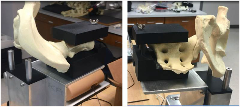
A mounting bracket was designed to hold an artificial hemi-pelvis, (Sawbones, model #1294–29) so that the working volume needed for the iliosacral screw procedure intersected with the working volume of the simulator’s optical system. The mounting bracket consists of 3 main components: an L bracket to provide a flat and rigid surface to mount onto, a 3D printed shell matching the bottom surface of the sacral body anatomy, and a 3D printed shell matching the top surface of the sacral body anatomy (Figure 5). Two specially designed surfaces reproducibly position the hemi-pelvis on, and clamp the hemi-pelvis to, the simulator.
Figure 5.
These oblique views show the pelvic bone mounted to this simulator base. The soft tissue is not shown here. The black 3D printed materials act as a vice to hold the pelvic model in place while residents drill into the bone.
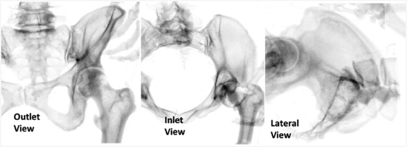
The simulator’s software was modified in order to display the proper images to the residents. CT data from the Visible Human Project® (https://www.nlm.nih.gov/research/visible/visible_human.html) was used to generate the fluoroscopic images used in the procedure (Figure 6). The procedure uses three main perspective views: an outlet view, inlet view, and lateral view. The inlet and outlet views are the main views used to navigate the guide wire. These two views are at an oblique angle relative to the patient, making it difficult to interpret wire trajectory and necessary adjustments. Learning to properly assess the wire trajectory in these views is considered one of the main skills of this procedure.
Figure 6.
The three views used in the iliosacral procedure are shown here. The inlet and outlet views are taken at oblique angles to a patient, and the lateral view is taken directly along the corridor of the iliosacral joint.
Iliosacral Screw Module Implementation
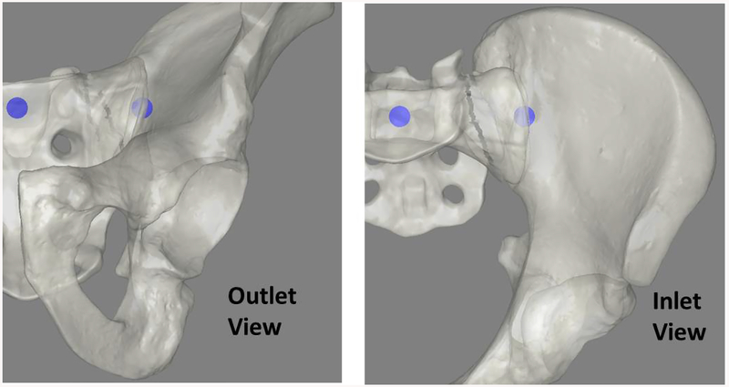
The new iliosacral simulator was pilot-tested with six, first-year orthopaedic residents. Residents were consented to participate in the study as part of an IRB approved research experiment (IRB ID #201409755). The residents were each presented with a task designed to train them to navigate their wire in the outlet view, inlet view, and in a combined 3D setting. The task involved a series of target bubble pairs overlaid on rendered fluoroscopic images (Figure 7). Residents held a surgical wire on the hemi-pelvis and oriented it so that a line projected along the wire intersected with both targets inside the bone. The task was intended to simulate the step in the surgical procedure when the surgeon orients the wire before drilling. For each series of target bubbles, the resident could try up to 5 wire adjustments to properly position their wire. If the wire was correctly positioned, a new pair of targets were presented, this time with a smaller bubble diameter. In the event that the resident failed after 5 tries, the new targets had a larger diameter. The starting target size had a diameter of 5 mm (0.2 inches). Residents were awarded 5 points for each accurately placed wire. Bonus points were awarded if multiple targets were hit in a row, and for hitting a target with a diameter less than the original target size.
Figure 7.
Starting views in the bubble game shown here. In the game cartoon depictions of the pelvic anatomy were used to make the targets more clear to the trainees. The blue circles act as targets for the residents to pierce with their wire during the training exercise.
As the residents used the simulator, data were also collected on how the simulator itself was performing. If an erroneous wire position was calculated or there was a problem in the simulator algorithm that resulted in no wire being shown to the resident, the raw image that was used for that requested fluoroscopic shot was saved to a repository. These images were later examined to understand if the errors were from a mechanical issue, like the simulator focus or working volume, an algorithmic issue, or a user error, such as having a hand obstructing the wire.
RESULTS
When quantifying the simulator accuracy, the two main metrics used were: wire tip accuracy and wire trajectory accuracy. In comparing calculated tip placements to known tip placements, the wire tip accuracy varied between 0.25 mm (0.01 inches) and 4.85 mm (0.19 inches) of error. On average the wire tip error was 1.7 mm (0.067 inches). The wire angle error varied between 0.04° and 4.3°. The average angle error was 1.31°. Across all tests, the average time to compute the pose was 1.05 seconds, well within the range of a typical fluoroscopic image acquisition in surgery. Table 1 shows the average error measurements of the 29 reference positions for the tip location and trajectory measurements across the different testing locations.
Table 1 –
The simulator accuracy is shown here. For each location, the simulator computed the wire tip position and trajectory in bone for all 29 laser scanned reference points. The average errors values for each of the 29 reference points at each new testing location is shown below.
| Location | Average Tip Error (mm) |
Average Angle Error (°) |
Average Computation Time (s) |
|---|---|---|---|
| Desktop | 1.53 | 1.15 | 1.12 |
| Dry Lab | 1.59 | 1.31 | 1.03 |
| Conference Room | 1.61 | 1.12 | 1.01 |
| Wet Lab | 1.97 | 1.18 | 1.08 |
| Library | 1.81 | 1.31 | 0.99 |
| Average | 1.70 | 1.31 | 1.05 |
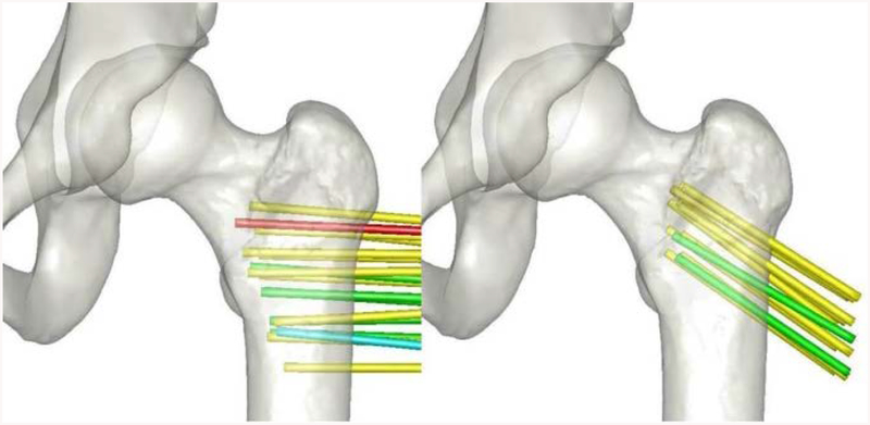
The system accuracy variation across the working volume of the simulator is another factor in consideration. For each wire reference position in bone, the accuracy was queried to examine any trends that might exist. Figure 8 shows a color-coded mapping of the wire positions in bone that span the working volume of the simulator. Most the wire positions had an accuracy in tip placement of 1 to 2 mm. The largest error was in a wire position near the edge of the working volume of the simulator, with an average error value greater than 3mm. Six wire positions had average errors of less than 1 mm which all trended towards the center of the working volume.
Figure 8.
Errors of the wire tip position, after projecting into bone for different wire positions. Average tip errors at each position are indicated by color: green for errors < 1mm, yellow for errors between 1 and 2mm, blue for errors between 2 and 3mm, and red for errors > 3mm.
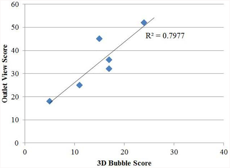
The performance of the residents participating in the bubble target practice exercise on the iliosacral module can be seen in Table 2. The average score on the inlet task was 33.3, meaning on average resident could hit the target at least 6 times in the inlet view during the training (5 points were awarded for each time a target was hit in that 2D plane). On the outlet view, the average score was 34.6, again suggesting that residents were able to hit the target at least 6 times on the outlet view during training. When looking at the combined 3D task however, the average score was 14.8, suggesting residents were only able to hit the 3D target 2 to 3 times during training. This suggests that correctly positioning the wire in a 3D position is a more challenging task than correctly positioning the wire in a single plane, which makes intuitive sense. What is not clear at first, however, is which plane is more difficult to maneuver in or contributes more heavily to the ability to correctly drive the wire in a 3D position. The correlation between each resident’s performance in the inlet view and their performance on the 3D task had an R squared value of 0.36. Likewise, the correlation between each resident’s performance in the outlet view and their performance on the 3D task had an R squared value of 0.79 (Figure 9).
Table 2 –
The scores of each residents’ performance on the iliosacral bubble targeting task is shown below. Residents were given 5 points for accurately hitting the bubble targets. Additional points were given when multiple targets were hit consecutively.
| Resident | Inlet View | Outlet View | Combined 3D Task |
|---|---|---|---|
| 1 | 20 | 25 | 11 |
| 2 | 19 | 18 | 5 |
| 3 | 39 | 52 | 24 |
| 4 | 31 | 45 | 15 |
| 5 | 30 | 36 | 17 |
| 6 | 61 | 32 | 17 |
Figure 9.
This graph illustrates the strong relationship between a resident’s performance on the target practice in the outlet view with the 3D target practice. Each residents’ performance on the outlet view bubble task is graphed on the y axis and the corresponding score on the 3D bubble task is shown on the x-axis. A strong correlation of R2 = 0.79 can be seen between these two metrics.
Over the course of training with six residents on the iliosacral target task, a total of 948 images were taken. Of these images, 74 (7.8%) triggered a failure in the system. Of these failures, 35 were due to a resident’s hand obstructing the view of the wire to the camera, 15 resulted from the wire being outside of the working volume of the simulator, 4 resulted from a poorly focused image, and 20 resulted from a flaw in the underlying simulator algorithm that was subsequently fixed.
DISCUSSION
Wire navigation is a central skill in the field of orthopaedics that has many applications. Developing a training tool that can encompass a variety of these applications has obvious benefits to the community of orthopaedic surgeons and ultimately the patients receiving the operation. Given the positive feedback our group has received when training residents with the wire navigation simulator for applications in the hip, we endeavored to explore the simulator platform’s ability to incorporate other wire navigation tasks. In this study, the simulator accuracy, working volume definition, and tactile feedback were the main criteria used to create a design space around which new simulator applications could be developed. We found that the simulator can accurately position the wire within an average of 1.7 mm (0.067 inches), 1.31°, and display the resulting image to a resident within 1.05 seconds. As the skill level of surgeon using the simulator increases, or the wire navigation application changes, this level of accuracy may be more or less sufficient. In the application of an iliosacral screw, residents are attempting to place the wire within a corridor of approximately 14 mm (0.55 inches) in diameter. Although no qualitative feedback was formally collected, it appeared that the accuracy of the images presented to the residents provided sufficient realism that the task was accepted as valid. In other applications, however, greater precision may be needed to convey the same level of realism. For instance, fractures in the hand can often be treated with a wire navigation technique. In these instances, the corridor a surgeon is trying to place the guide wire in may only be slightly larger than the simulator can accurately place the wire. In these instances, design parameters of the simulator, such as the resolution of the optical system, may need to be altered to provide the necessary precision.
Apart from characterizing the accuracy of the simulator, this study also examined how the accuracy varied across the working volume. Figure 8 illustrates that although there is not a large bias or pattern observed, the accuracy of the simulator decreases slightly as one moves to the edges of the optical viewing frame. The wire locations that had an average precision of less than 1 mm (0.039 inches) are generally located at the center of the working volume. Only two testing locations placed the wires with accuracy error greater than 2 mm (0.079 inches) and both of these locations are near the far edge of the working volume. This result is somewhat expected, as the center of the working volume would be where the camera is most in focus, and at the edges of the working volume the camera would begin to lose focus. This may be an important design element to consider in future application developments as varying levels of precision and working volume are required.
Implementing the iliosacral targeting task was an important step in testing the design of the new module. Although the theoretical model satisfied the design criteria, there are always unexpected issues that only present themselves when real users engage with a device. In this instance, the analysis of the flagged system failures during use illustrated two unexpected findings. First, most errors came from residents placing their hand on the wire while requesting an image. This type of behavior illustrates the disconnect that can sometimes occur between behavior in the operating room and in a simulated environment. In the operating room, it is common for surgeons to support the guide wire with their hand to ensure that they are aiming in the trajectory that they intend to drill the wire. Given a simulator should never stifle behavior that relates to operating room, this presents a design challenge that may need to be tackled in future iterations. However, placing a hand in the view does come at the expense of additional radiation exposure to the surgeon. The second behavior that was unexpected was wires being placed outside of the working volume of the simulator, accounting for 15 of the 74 system failures. Although the theoretical working volume of the simulator should have been more than sufficient in comparison to the working volume of the procedure defined during the literature review, it may be that learners have behaviors that take them outside these boundaries. Additionally, the soft tissues provided around the artificial bone gave little indication as to the limits of the optical system. It could be that if some sort boundary line was drawn on the soft tissue, this would prevent these types of errors from occurring. However, that may be used as information to guide the residents in their placement of the wire that is not available in the operating room.
The results of the iliosacral targeting task showed a strong link between a resident’s ability to direct a guide wire on an outlet view and their ability to direct a guide wire in a 3D targeting task (Figure 9). This suggests that the outlet view may be more difficult to interpret or maneuver in, and thus practice in this plane holds the key to resident improvement on the iliosacral screw task. Although both views are critical to the success of the procedure, this result could help reduce complications during this type of procedure, as the outlet view is the main view that allows the surgeons to see where their wire is traveling relative to nerve root paths. Perhaps by placing more emphasis on learning to navigate in this plane, surgeons will have better place implants across the sacroiliac joint and will lead to fewer complications for patients.
A potential limitation of this study would be the small sample size of residents who have used the iliosacral module on the wire navigation simulator. As more residents are exposed to this task, some of the patterns of behavior seen in this study may change or become less evident. Additionally, all the residents who interacted with the module were first year novice surgeons. Given that iliosacral screw placement is a relatively advanced task, it would make sense to target a more advanced level of surgeon. In this instance, the more experienced surgeons may not so easily accept the accuracy or resolution of the system and may find it does not adequately reflect their experience in the operating room.
CONCLUSIONS
This study has successfully demonstrated the ability to adapt an existing wire navigation platform originally developed for a hip application to new applications such as an iliosacral screw placement. Through a careful examination of the existing capabilities of the simulator and needed capabilities of other procedures, the simulator could be modified to present the new surgical application for iliosacral screw placement. Further, testing with orthopaedic residents has demonstrated the simulator reliability in the new application and begun to illustrate a new relationship between navigating in a single plane and a 3D space that may exist. Further testing with additional residents will be needed to validate the iliosacral module as an effective training tool for orthopaedic surgeons.
ACKNOWLEDGEMENTS
This work was partially supported by grants from the American Board of Orthopaedic Surgery as well as the Agency for Healthcare Research and Quality, United States (Grant no. 1 R18 HS022077 and no. 5 R18 HS025353).
Contributor Information
Steven Long, Department of Orthopaedics and Rehabilitation, 2181 Westlawn, The University of Iowa, Iowa City, IA 52242.
Geb W. Thomas, Department of Mechanical and Industrial Engineering, 2404 Seamans Center for the Engineering Arts and Sciences, The University of Iowa, Iowa City, IA 52242
Donald D. Anderson, Department of Orthopaedics and Rehabilitation, 2181 Westlawn, The University of Iowa, Iowa City, IA 52242, ASME member since 1988
References
- [1].ACGME Highlights Its Standards on Resident Duty Hours. Available from: http://www.acgme.org/acgmeweb/tabid/363/Publications/Papers/PositionPapers/HighlightsItsStandardsonResidentDutyHours.aspx. Accessed 5/20/2018
- [2].ACGME Program Requirements for Graduate Medical Education in Orthopaedic Surgery. https://www.acgme.org/Portals/0/PFAssets/ProgramRequirements/260_orthopaedic_surgery_2017-07-01.pdf. Accessed 5/20/2018
- [3].Ferguson PC, Kraemer W, Nousiainen M, Safir O, Sonnadara R, Alman B, Reznick R. Three-Year experience with an innovative, modular competency-based curriculum for orthopaedic training. J Bone Joint Surg Am. 2013. November 95 (21)e166. [DOI] [PubMed] [Google Scholar]
- [4].Khanduja V, Lawrence JE, and Audenaert E, Testing the Construct Validity of a Virtual Reality Hip Arthroscopy Simulator. Arthroscopy, 2017. 33(3): p. 566–571. [DOI] [PubMed] [Google Scholar]
- [5].Lopez G, et al. , Construct Validity for a Cost-effective Arthroscopic Surgery Simulator for Resident Education. Journal of the American Academy of Orthopaedic Surgeons, 2016. 24(12): p. 886–894. [DOI] [PubMed] [Google Scholar]
- [6].Tay C, Khajuria A, and Gupte C, Simulation training: a systematic review of simulation in arthroscopy and proposal of a new competency-based training framework. Int J Surg, 2014. 12(6): p. 626–33. [DOI] [PubMed] [Google Scholar]
- [7].Carpenter JE, et al. ABOS Surgical Skills Modules for PGY-1 Residents. Available from: https://www.abos.org/abos-surgical-skills-modules-for-pgy-1-residents.aspx. Accessed 5/20/2018
- [8].Long SA, Thomas GW, Anderson DD. Designing an affordable wire navigation surgical simulator. J Med Devices. 2016. Sept 10(3):030921. [DOI] [PMC free article] [PubMed] [Google Scholar]
- [9].Hip Fractures Among Older Adults. Available from: https://www.cdc.gov/homeandrecreationalsafety/falls/adulthipfx.html. Accessed 5/20/2018
- [10].Technical Specification Sheet for the Edge FaroArm and ScanArm. Available from: https://knowledge.faro.com/Hardware/FaroArm_and_ScanArm/USB_FaroArm/Technical_Specification_Sheet_for_the_Edge_FaroArm_and_ScanArm?mt-learningpath=faro_edge_downloads. Accessed 5/20/2018
- [11].Bydon, K. Mohamad, De La Garza-Ramos, K. Rafael, Macki, K. Mohamed, Desai, K. Atman, Gokaslan, K. Aaron, & Bydon, K. Ali. (2014). Incidence of Sacral Fractures and In-Hospital Postoperative Complications in the United States: An Analysis of 2002–2011 Data. Spine, 39(18), E1103–E1109. [DOI] [PubMed] [Google Scholar]
- [12].Riehl, & Widmaier. (2012). A Simulator Model for Sacroiliac Screw Placement. Journal of Surgical Education, 69(3), 282–285. [DOI] [PubMed] [Google Scholar]
- [13].Broder JM (2004). In science’s name, lucrative trade in body parts. The New York times,A1, A16–A16. [PubMed] [Google Scholar]
- [14].Tonetti J, Overschelde J, Sadok B, Vouaillat H, Eid A. Percutaneous ilio-sacral screw insertion. Fluoroscopic techniques. Orthop Traumatol Surg Res. 2013. [DOI] [PubMed] [Google Scholar]
- [15].Alvis-Miranda HR, Farid-Escorcia H, Alcalá-Cerra G, Castellar-Leones SM, & Moscote-Salazar LR (2014). Sacroiliac screw fixation: A mini review of surgical technique. Journal of Craniovertebral Junction & Spine, 5(3), 110–113. 10.4103/0974-8237.142303 [DOI] [PMC free article] [PubMed] [Google Scholar]
- [16].Keating J, Werier J, Blachut P, Broekhuyse H, Meek R, O’brien P. Early fixation of the vertically unstable pelvis: the role of iliosacral screw fixation of the posterior lesion. J Orthop Trauma 1999;13(2):107–713. [DOI] [PubMed] [Google Scholar]
- [17].Tonetti J, Carrat L, Blendea S, Merloz P, Troccaz J, Lavallée S, et al. Clinical results of percutaneous pelvic surgery. Computer assisted surgery using ultrasound compared to standard fluoroscopy. Comput Aided Surg 2001;6 (4):204–411. [DOI] [PubMed] [Google Scholar]
- [18].Routt MC Jr, Simonian PT, Mills WJ. Iliosacral screw fixation: early complications of the percutaneous technique. J Orthop Trauma 1997;11 (8):584–9. [DOI] [PubMed] [Google Scholar]
- [19].Mendel T, Radetzki F, Wohlrab D, Stock K, Hofmann G, & Noser H (2013). CT-based 3-D visualisation of secure bone corridors and optimal trajectories for sacroiliac screws. Injury, 44 7, 957–63. [DOI] [PubMed] [Google Scholar]


