Abstract
Background Flexor tendon injury is a rare but serious complication of distal radius volar plating.
Purpose This study aims to determine whether the design of distal radius volar plates impacts the amount of force exerted on the flexor digitorum profundus (FDP) and flexor pollicis longus (FPL) tendons when the plates are placed proximal and distal to the watershed line.
Methods Three commercially available plates were applied to 10 fresh, matched-pair upper extremity specimens. Cyclical loading was applied to the tendons, and the force generated between tendon and plate was measured. Linear mixed effect models were used to evaluate differences in maximum and mean forces by plate position, plate design, and the interaction between position and design.
Results Forces on the tendons differed significantly by position but not plate design. For the FPL tendon, the average maximum force with a plate in Soong's grade 2 was 4.50 (95% confidence interval [CI]: 2.8–7.3) times higher than when the plate was in a Soong's grade 0 placement, and 4.63 (95% CI: 2.82–7.61) times higher for the FDP tendon. While not statistically significant, lower observed force values with thinner plates when plates were placed distal to the watershed line suggest that that plate thickness could also be a critical plate characteristic for distally placed plates.
Conclusion Despite differences in plate design, the main determinant of plate prominence and therefore flexor tendon injury potential is placement in relation to the watershed line.
Clinical Relevance This study may help to guide surgeon implant selection and volar plate design.
Keywords: distal radius fracture, distal radius volar plate, flexor tendon injury, tendon rupture, watershed line
Distal radius fractures are common, with over 640,000 cases occurring in the United States annually. 1 About 16% of these are surgically treated with a volar plate. 2 Volar plating has become the most common method for treating unstable distal radius fractures due to improved functional outcomes, earlier mobilization, and prevention of malunion. 3 4 5 Because of this popularity, it is no wonder that over 40 different plates with a variety of designs are available in the marketplace. Uncommon but serious complications can occur with volar plating, including tendon irritation and rupture, median nerve damage, and loss of reduction, all of which translate into increased morbidity and need for additional surgeries and cost. 6 Flexor tendon rupture is the most well described late complication, with rates reported between 0.8 to 12%, 7 8 9 and a recent meta-analysis finding the incidence to be 1.5%. 10 The two most common flexor tendons affected are the flexor pollicis longus (FPL) and the index flexor digitorum profundus (FDP), which are associated with 57 to 75 and 15% of cases, respectively. 11 12 A well-recognized factor leading to tendon irritation is plate placement in relation to the most distal volar ridge of the radial metaphysis, known as the watershed line. 8 11 13 14 15 16 17 Distal to this line, increased surface area of contact 14 and therefore glide friction 15 17 lead to tendon injury which is not always symptomatic until a tendon ruptures. Newer studies have demonstrated that plate prominence (and therefore greater impingement on tendons) can also result from not restoring the native volar tilt of the distal radius after fracture. 16 Without the native tilt, an otherwise well placed plate is more prominent in comparison to the maximal height of the radius, and therefore comes into contact with the tendons at smaller degrees of wrist extension.
Reducing the incidence of tendon injury has been a motivating force behind recent innovations in plate design, with modifications such as lower profiles, variable-angle locking screws, central concavity or Y -shaped, specifically to decrease contact along the path of the FPL. However, tendon irritation and ruptures continue to occur and it is not clear whether these modifications have indeed led to decreased tendon injury, and if any of the new generation plates is superior in this respect. Recent literature attempting to address this question has demonstrated substantial differences both in surface area of different plates beneath the FPL and in the prominence of different plates. 14 When taken in concert with the finding that plate prominence is a risk factor for tendon rupture, we believe these results suggest that plate design may have the potential to decrease the rate of this morbidity.
The purpose of this biomechanical cadaver study is to answer the question of whether three variations of distal radius plate design impact the amount of force exerted on the FDP and FPL tendons when the plates are placed proximal and distal to the watershed line.
Materials and Methods
Study Design
Ten fresh-frozen, matched-pair distal forearm to hand specimens were obtained from our university body donation program (mean age, 76.6 years; range, 66–87 years). Radiographs of the specimens confirmed no evidence of prior trauma. With respect to the plate selection, we chose three commercially available Medartis (Basel, Switzerland) plate designs ( Fig. 1 ). These designs were selected because they were precontoured, with manufacturer recommended fixation proximal to the watershed line. We specifically included a Y -shaped, FPL sparing plate, as previous literature had suggested less potential area of contact between tendon and plate with this design. 14 We selected a range of plate thicknesses, from 1.6 to 2.0 mm. Specific plate details can be found in Fig. 1 , but for the purposes of the text, the designs will be referred to as the Babyfoot plate, FPL plate, and Adaptive plate (2.5 TriLock Distal Radius Volar Plates, Medartis, Basel, Swiitzerland). As described in more detail below, these plates were fixed to the distal radii in either a proximal or distal position. The specimens were then immobilized with an external fixator and mounted on a custom jig in pinch position. External cyclical force was applied to the FPL or FDP tendons, and the force between the tendon and plate measured with a thin, flexible sensor.
Fig. 1.
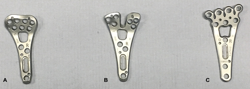
2.5 TriLock Distal Radius Volar Plates, Medartis (Basel, Swiitzerland). ( A ) Adaptive plate, 2.0 mm thick, 23.0 mm wide, titanium; ( B ) FPL plate, 2.0 mm thick, 25.0 mm wide, titanium; ( C ) Babyfoot plate, 1.6 mm thick, 27.0 mm wide, titanium. FPL, flexor pollicis longus.
Experimental Manipulations
The distal radius was exposed using the interval between the flexor carpi radialis and the radial artery. Care was taken to maintain the FPL and FDP in their anatomic positions by maintaining the carpal tunnel boundaries. The pronator quadratus (PQ) was incised and elevated from radial to ulnar. Of note, we did not return the PQ to its anatomic position after plating, as this is often not done as a part of general practice 18 and the problem of tendon rupture can persist despite PQ reconstruction. 19 During dissection, we sprayed the arm every 10 minutes with normal saline to prevent the tendons from drying out.
One of the three plates was fixed to the distal radius. Each plate was fixated in two anatomic positions; proximal to the watershed line and distal to the watershed line. These positions corresponded to a Soong 0 and a Soong 2 grades according to the plate fixation classification system developed by Soong et al 8 ( Fig. 2 ). We trialed each plate on every wrist, for a total of 60 different plate–bone combinations. For a control, in the last nine wrists, we ran trials without a plate in place. The sensor was placed either proximal to or at the watershed line, for an additional 18 tests and a total of 78 tests for each tendon. Because the FDP and FPL tendons were tested individually, we ran a total of 156 tests. In an effort to reduce any bias associated with the order of fixation, each plate was fixated first, second, and third, three to four times. The order of positioning (proximal or distal) was additionally randomized. K-wires were used to secure the plate, and positioning confirmed by fluoroscopy. Next, the plate was fixated to the radial shaft using a nonlocking cortical screw into the gliding slot hole. Up to three compression screws were then placed distally, to compress the plate flush with the distal cortex. Placement was again confirmed with fluoroscopy.
Fig. 2.
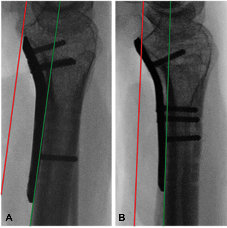
lateral radiographs of plate placement relative to the critical line (red), which represents a line tangential to the most volar extent of the volar rim (the watershed line) and parallel to the volar cortical bone of the radial shaft (green line). ( A ) Soong's grade 0, dorsal to the critical line ( B ) Soong's grade 2, volar to the critical line and distal to the volar rim.
After plating, the wrists were immobilized in an external fixator (Agee WristJack, Hand Biomechanics Laboratory, Inc, Sacramento, CA). To mimic functional grasp, the wrist was locked in 30–35 degrees (mean, 32 degrees) of wrist extension and 5–10 degrees (mean, 7 degrees) of ulnar deviation. The external fixator was then mounted on to a custom jig.2 FiberWire suture (Arthrex, Naples, FL) was used to attach either the FPL or the FDP tendon to a motor with a rotating arm (Hitec Inc., Poway, CA). The stall torque of the motor was 5.2 kg/cm, and the motor arm was 3 cm long. The motor was attached to an Arduino microcontroller (Arduino Software, Turin, Italy) and programmed to move cyclically between 0 and 60 degrees (maximum flexion occurring at 60 degrees) at a rate of 0.125 Hz. Tendon displacement was resisted by springs that attached the nail of the thumb or index finger to the jig. When testing the force between the plate and the FPL tendon, the spring was attached to the thumb and the motor to the FPL tendon alone. When measuring force on the FDP to the index, the spring was attached to the index finger and the motor arm to the FDP tendon alone. In this manner, we were able to get cyclical force measurements as the motor pulled on the tendon when the motor arm rotated away, fully flexing the digit, and the springs pulled the digit back to full extension when the motor arm rotated toward the specimen ( Fig. 3 ). The approximate load on each tendon was determined by the extension of the springs. The K constant of the spring attached to the thumb was 9.25 N/cm, with an average maximum displacement of 2 cm. The K for the spring attached to the index finger was 3.1 N/cm and the average maximum displacement for the spring was 3.5 cm. Therefore, the average load on the FPL tendon was 18.5 N and on the FDP was 10.9 N. To ensure consistent resistance against the motor, springs were replaced once their K-constant or initial length changed.
Fig. 3.
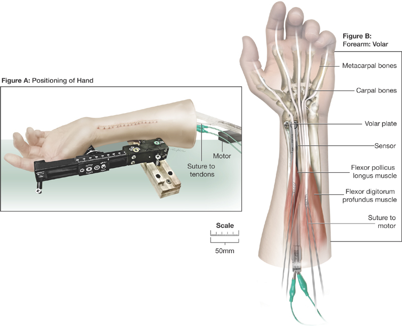
After plating, forearms were immobilized with an external fixator and mounted on custom jig. Suture was used to attach the FPL and FDP tendons to a motor. Contact pressure between the respective tendons and plates was measured with a thin plastic sensor, from which pressure measurements were obtained. Once the sensor was secured, the arm soft tissue was closed and the jig was run for five cycles of flexion and extension for each tendon. FDP, flexor digitorum profundus; FPL, flexor pollicis longus.
Outcome Measures
We measured contact force using a thin plastic sensor (Flexiforce model A201, Tekscan, Boston, MA), with a sensing area of 71.3 mm 2 and a 0 to 4.4 N range. The sensor was connected to a personal computer via a microcontroller, and real-time force measurements were recorded using a program (Arduino Software, Turin, Italy). Prior to being calibrated, the sensor was covered with clear plastic tape to prevent error caused by moisture. The sensor was then calibrated prior to each testing session using calibration weights. To ensure sensor performance, the tape-covered sensor was calibrated at the beginning of every testing day, with every new arm tested, and when the plastic tape or sensor was replaced. A calibration curve was made from premeasured weights ranging from 10 to 240 g (downward force of 0–2.4 N). The sensor was replaced if could not produce consistent measurements during calibration or when the arm was stationary. After calibration, the sensor was secured in place between the tendon and the plate with 6–0 Prolene Suture (Ethicon, Somerville, NJ). The sensor was moved, so that it lay directly below the FPL or FDP tendons, depending on which tendon was being animated. Once the sensor was secured, soft tissue was closed and the specimens were run through five cycles of flexion and extension. A representative graph of obtained force values is demonstrated in Fig. 4 .
Fig. 4.
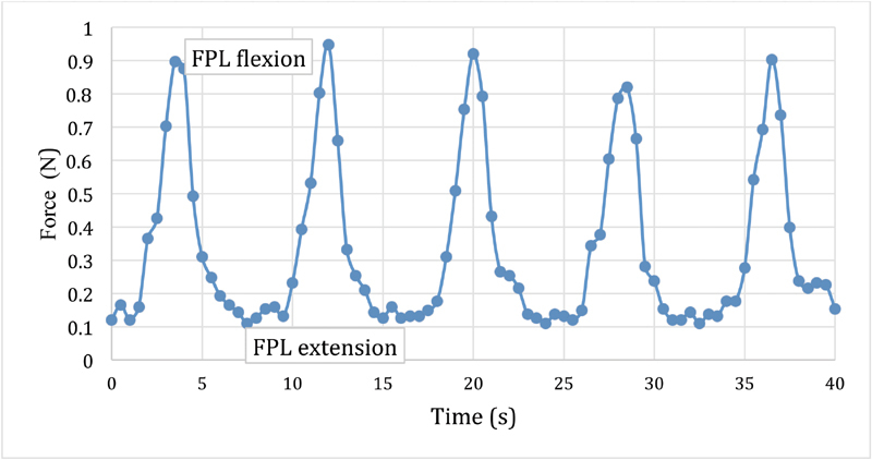
The jig was run through five cycles of flexion and extension for each tendon and real time pressure values obtained.
Statistical Analysis
The primary outcomes of interest were the maximum and the mean forces exerted on tendon by the different plates at the Soong's grades 0 and 2 positions during cyclical movement of the FPL and FDP tendons Maximum and mean forces were log transformed to meet assumptions of the statistical models. Linear mixed effect models were used to evaluate differences in maximum and mean force by plate position, plate design, and the interaction between position and design. Random effects for subject and for arm nested within subject were included to account for correlation of values. Models were fit using PROC MIXED in SAS Version 9.4 (Cary, NC). All tests were two sided and evaluated at a significance level of 0.05.
Results
FPL Tendon
The raw force values (in Newton) recorded on the FPL tendon are shown in Table 1 . The maximum force experienced by the FPL tendon varied significantly by plate prominence; in Soong's grade 2 forces were 4.5 (95% confidence interval [CI]: 2.8–7.3, p = 0.001) times higher than when plates were in a Soong's grade 0 placement. Similarly, the mean force values on the FPL tendon were significantly greater with the more prominent plate (5.3 times higher at Soong's grade 2, CI: 3.11–9.09, p = 0.001). When comparing plate types, the maximum and mean forces recorded on the FPL tendon did not vary significantly by plate type at either position (maximum: p = 0.139; mean: p = 0.103) When plates were in a Soong's grade 2 placement, force tended to be lower with the Babyfoot plate, although differences were not statistically significant ( Fig. 5 ).
Table 1. Median (25th, 75th quartiles) for maximum and mean values of forces (Newton) on FPL and FDP tendons for each Soong's position and plate type.
| FPL tendon | FDP tendon | ||||
|---|---|---|---|---|---|
| Soong's grade | Plate | Maximum force (N) | Mean force (N) | Maximum force (N) | Mean force (N) |
| 0 | 0 | 0.10 (0.07, 0.13) | 0.04 (0.02, 0.10) | 0.10 (0.06, 0.14) | 0.03 (0.02, 0.09) |
| 2 | 0 | 0.28 (0.19, 0.62) | 0.16 (0.12, 0.25) | 0.35 (0.32, 0.43) | 0.16 (0.14, 0.31) |
| 0 | 1 | 0.94 (0.05, 0.21) | 0.05 (0.03, 0.17) | 0.16 (0.08, 0.34) | 0.11 (0.04, 0.18) |
| 2 | 1 | 0.90 (0.63, 1.56) | 0.46 (0.39, 0.61) | 0.91 (0.65, 1.58) | 0.50 (0.31, 0.78) |
| 0 | 2 | 0.09 (0.06, 0.12) | 0.05 (0.02, 0.07) | 0.13 (0.09, 0.18) | 0.06 (0.04, 0.10) |
| 2 | 2 | 1.02 (0.43, 1.68) | 0.56 (0.21, 1.00) | 1.03 (0.51, 1.19) | 0.67 (0.28, 0.96) |
| 0 | 3 | 0.11 (0.09, 0.27) | 0.06 (0.03, 0.21) | 0.12 (0.10, 0.22) | 0.07 (0.05, 0.19) |
| 2 | 3 | 0.47 (0.19, 1.79) | 0.27 (0.10, 1.14) | 0.42 (0.24, 1.35) | 0.27 (0.14, 0.83) |
Abbreviations: FDP, flexor digitorum profundus; FPL, flexor pollicis longus; N, Newton.
Note: Plate type of 0 is no plate, and this box indicates force values obtained when the sensor alone was placed either proximal to or at the watershed line.
Fig. 5.
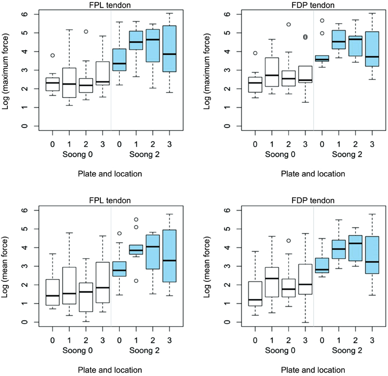
Boxplots show the log transformed values of maximum and mean force on FPL and FDP tendons by plate type and location. Force was log transformed. Plate 0: no plate; plate 1: Adaptive plate; plate 2: FPL plate; PLate 3: Babyfoot plate. FDP, flexor digitorum profundus; FPL, flexor pollicis longus.
FDP-Index Tendon
The raw values of the maximum and mean forces on the FDP tendon with each plate are shown in Table 1 . Similar to the FPL tendon, the maximum force on the FDP tendon to the index finger is also differed significantly with plate prominence; 4.63 (95% CI: 2.82–7.61) times higher when the plate had a Soong's grade 2 prominence versus a Soong's grade 0 ( p = 0.001). Also following this trend, the mean force values on the FPL tendon were significantly greater with the more prominent plate (4.9 [95% CI: 2.68–8.96], p = 0.002). The differences in the maximum and mean forces by plate type at the different plate positions did not achieve statistical significance (maximum: p = 0.123; mean: p = 0.153). Again, a nonsignificant tendency of decreased force on the tendons was observed with the Babyfoot plate when plated in a Soong's grade 2 position ( Fig. 5 ).
Discussion
The use of volar plates to treat distal radius fractures has risen dramatically since first described in 2000. 20 With increasing popularity, recognition of the complications, and interest in avoiding any morbidity related to volar plating has come better. Beyond the distress of both surgeon and patient, this attention is also justified from a cost standpoint. Distal radius hardware removal for plate prominence and tendon rupture cost the health care system over $15.2 million annually, 10 21 22 23 and this surgical expense is dwarfed by the cost of time of work, extra clinic visits, therapy, prescription drug, and caretaker costs, which easily double or even triple this number. 2 This expense is an additional motivating force toward design innovation, which has succeeded in bringing a plethora of new plates to market. However, the rate of development has far outpaced the data regarding whether the different designs can actually decrease tendon injury.
Study Limitations
The number of specimens used represents a limitation of our study. The large differences in force between the Soong's grades 2 0 were evident even in this small study, but force differences among plate designs were smaller and therefore we may have been underpowered to see a statistically significant difference.
There were several other limitations to our study related to using a cadaver model. Cadaver studies are good approximation of the clinical setting but do not recreate it. Placement of our plates was based only on “best fit” on the radius and desired Soong's grade, without a fracture to contend with. Our dissection was wider than would be done in a clinical setting, which may have slightly moved or changed the tendons in a three-dimensional plane. The moisture level within the arm, while roughly accounted for using a spray bottle, could have impacted tendon glide and possibly pressure on the plates. While fixing multiple plates to the same specimen may have impacted screw placement and fixation, we rotated the order of plate placement to minimize this potentially confounding factor.
An additional limitation is that we only tested plates from one company. We believe that our conclusions could be extrapolated to similar constructs but having not tested these plates we cannot ensure that our results are generalizable.
Discussion of the Question: Does Plate Design Impact the Force on Flexor Tendons?
Our data confirm prior literature with the finding that plate prominence due to distal placement increases the force of the plate on both the FPL and FDP tendons to a significant degree. We did not find that volar plate design significantly impacted either the mean or median force between the plate and flexor tendons. This finding was consistent whether the plate was distal or proximal to the watershed line. In our study, a trend was seen toward decreased force on tendons with the Babyfoot plate (the thinnest plate at 1.6 mm, Fig. 1 ) when plates were placed in a Soong's grade 2 position. This finding suggests that when plates are already prominent due to distal placement, plate thickness could be a contributing factor to prominence and consequentially force on the tendons. While a potentially and clinically relevant finding, additional studies are necessary to verify and quantify this observation. What can be stated with confidence is that any variability in force on the tendons from plate design is vastly overshadowed by differences in plate prominence related to plate placement.
In examining, why the design of the FPL sparing plate did not lead to a decrease in force on the FPL tendon, one possible explanation could be related to the variability in “fit” of the FPL plate beneath the FPL tendon. When the FPL tendon fits well into the Y -groove of the plate ( Fig. 6 ), contact pressures were low. However, we found that with different widths of the distal radius, the FPL did not always fit perfectly into the Y -groove. For these arms, the tendon had more contact with the plate and the force values were higher, leading to substantial variability in observed force values ( Fig. 5 ). Previous studies on plate design have shown decreased contact surface area (as measured by statistical modeling of the FPL location over plates secured to stripped cadaver bone) and plate prominence with the FPL sparing, Y -shaped plates placed distal to the watershed line. 14 We believe that we were able to see greater variability in the contact between the FPL tendon and FPL plate due to an increased number of specimens (10 as opposed to five) and the fact that we were measuring contact force in situ as opposed to surface area of plate beneath an “ideal” FPL path and extrapolating information about contact pressures.
Fig. 6.
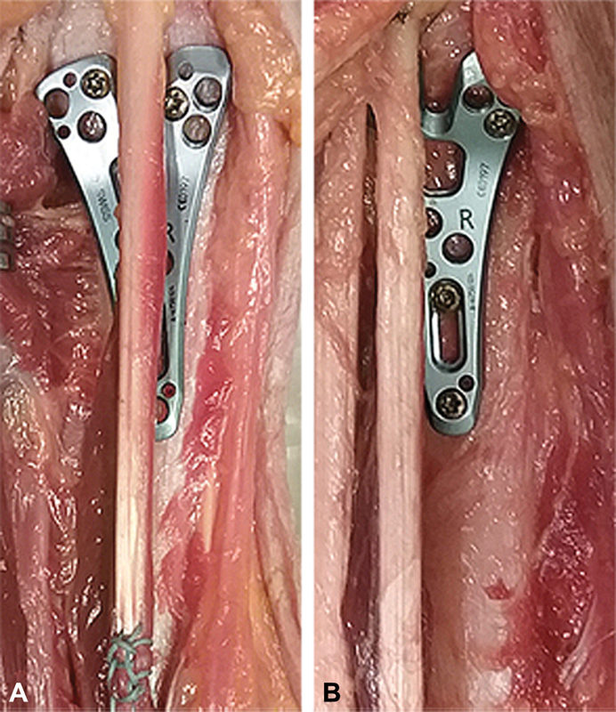
Differences in alignment between FLP tendon and FPL plate; ( A ) ideal fit, where FPL tendon sits in Y -groove ( B ) not ideal fit, where FPL tendon runs over Y -arm. FDP, flexor digitorum profundus; FPL, flexor pollicis longus.
It is worth noting here that glide friction exists between plate and tendon at any plate position on the radius when the wrist is in a functional position, as demonstrated previously by Tanaka et al 17 and again in our study. Indeed, we demonstrate that contact pressures exist even without plates, which suggest that it may not just be the contact pressure but also the material of the plate that contributes to tendon injury. This raises the hypothesis that, while no clinical studies have demonstrated a benefit of PQ repair over the plate, 24 there may be an advantage in covering plates to prevent the flexor tendons from contacting metal. Titanium and titanium alloys in particular have been shown to be irritating to tendons. 25 Currently available studies may be underpowered to detect the clinical value of PQ repair.
Conclusion
Plate prominence beneath the flexor tendons determines the contact force and therefore injury potential. The main determinant of prominence is plate placement in relation to the watershed line. Our results do not clearly show superiority of one plate type but suggest that decreasing the overall plate profile may have greater utility in preventing flexor tendon injury than anatomic plate design based on the “ideal” radius 26 27 28 . For complex fractures, the future may be in individualized plate customization, perhaps via three-dimensional printing, 29 or in advances in metallurgy, in pursuit of an ultrathin, strong, nonreactive plate.
Acknowledgments
The authors thank the individuals who donate their bodies and tissues for the advancement of education and research. They also thank Sarah St. Claire for her technical assistance with the illustrations.
Funding Statement
Funding The project described was supported by the National Center for Advancing Translational Sciences, National Institutes of Health (Grant # UL1 TR001860). Funding for the cadaver arms and plates was provided by a generous educational grant from Medartis.
Conflict of Interest None declared.
Note
This article, entitled “Impact of Design on Force between the Tendons and Distal Radius Volar Plates,” and its authors adhere to the ethical standards described by the Committee on Publication Ethics and the International Committee of Medical Journal Editors.
Authors' Contributions
Dr. K.M.H. is principally responsible for the experimental design, cadaver testing, and manuscript preparation. Dr. I.V. and Ms. X.I. assisted with experimental design and cadaver testing. Author X.I. additionally played a significant role in experimental design and execution, including motor and sensor calibration. Dr. S.T. was the principal statistician and is also responsible for Fig. 4 and Table 1 . Dr. R.M.S., as the senior author of this manuscript, provided invaluable guidance regarding experimental design, as well as critical manuscript editing. All of the authors have read and approved the final submitted manuscript.
References
- 1.Chung K C, Spilson S V. The frequency and epidemiology of hand and forearm fractures in the United States. J Hand Surg Am. 2001;26(05):908–915. doi: 10.1053/jhsu.2001.26322. [DOI] [PubMed] [Google Scholar]
- 2.Shauver M J, Yin H, Banerjee M, Chung K C. Current and future national costs to medicare for the treatment of distal radius fracture in the elderly. J Hand Surg Am. 2011;36(08):1282–1287. doi: 10.1016/j.jhsa.2011.05.017. [DOI] [PubMed] [Google Scholar]
- 3.Mackenney P J, McQueen M M, Elton R. Prediction of instability in distal radial fractures. J Bone Joint Surg Am. 2006;88(09):1944–1951. doi: 10.2106/JBJS.D.02520. [DOI] [PubMed] [Google Scholar]
- 4.Grewal R, MacDermid J C, King G J, Faber K J. Open reduction internal fixation versus percutaneous pinning with external fixation of distal radius fractures: a prospective, randomized clinical trial. J Hand Surg Am. 2011;36(12):1899–1906. doi: 10.1016/j.jhsa.2011.09.015. [DOI] [PubMed] [Google Scholar]
- 5.Chung K C, Kotsis S V, Kim H M. Predictors of functional outcomes after surgical treatment of distal radius fractures. J Hand Surg Am. 2007;32(01):76–83. doi: 10.1016/j.jhsa.2006.10.010. [DOI] [PubMed] [Google Scholar]
- 6.Bentohami A, de Burlet K, de Korte N, van den Bekerom M P, Goslings J C, Schep N W. Complications following volar locking plate fixation for distal radial fractures: a systematic review. J Hand Surg Eur Vol. 2014;39(07):745–754. doi: 10.1177/1753193413511936. [DOI] [PubMed] [Google Scholar]
- 7.Al-Rashid M, Theivendran K, Craigen M A. Delayed ruptures of the extensor tendon secondary to the use of volar locking compression plates for distal radial fractures. J Bone Joint Surg Br. 2006;88(12):1610–1612. doi: 10.1302/0301-620X.88B12.17696. [DOI] [PubMed] [Google Scholar]
- 8.Soong M, Earp B E, Bishop G, Leung A, Blazar P. Volar locking plate implant prominence and flexor tendon rupture. J Bone Joint Surg Am. 2011;93(04):328–335. doi: 10.2106/JBJS.J.00193. [DOI] [PubMed] [Google Scholar]
- 9.White B D, Nydick J A, Karsky D, Williams B D, Hess A V, Stone J D. Incidence and clinical outcomes of tendon rupture following distal radius fracture. J Hand Surg Am. 2012;37(10):2035–2040. doi: 10.1016/j.jhsa.2012.06.041. [DOI] [PubMed] [Google Scholar]
- 10.Azzi A J, Aldekhayel S, Boehm K S, Zadeh T. Tendon rupture and tenosynovitis following internal fixation of distal radius fractures: a systematic review. Plast Reconstr Surg. 2017;139(03):717e–724e. doi: 10.1097/PRS.0000000000003076. [DOI] [PubMed] [Google Scholar]
- 11.Asadollahi S, Keith P P. Flexor tendon injuries following plate fixation of distal radius fractures: a systematic review of the literature. J Orthop Traumatol. 2013;14(04):227–234. doi: 10.1007/s10195-013-0245-z. [DOI] [PMC free article] [PubMed] [Google Scholar]
- 12.Monaco N A, Dwyer C L, Ferikes A J, Lubahn J D. Hand surgeon reporting of tendon rupture following distal radius volar plating. Hand (N Y) 2016;11(03):278–286. doi: 10.1177/1558944715620792. [DOI] [PMC free article] [PubMed] [Google Scholar]
- 13.Kitay A, Swanstrom M, Schreiber J J et al. Volar plate position and flexor tendon rupture following distal radius fracture fixation. J Hand Surg Am. 2013;38(06):1091–1096. doi: 10.1016/j.jhsa.2013.03.011. [DOI] [PubMed] [Google Scholar]
- 14.Limthongthang R, Bachoura A, Jacoby S M, Osterman A L. Distal radius volar locking plate design and associated vulnerability of the flexor pollicis longus. J Hand Surg Am. 2014;39(05):852–860. doi: 10.1016/j.jhsa.2014.01.038. [DOI] [PubMed] [Google Scholar]
- 15.Matityahu A M, Lapalme S N, Seth A, Marmor M T, Buckley J M, Lattanza L L. How placement affects force and contact pressure between a volar plate of the distal radius and the flexor pollicus longus tendon: a biomechanical investigation. J Hand Surg Eur Vol. 2013;38(02):144–150. doi: 10.1177/1753193412453436. [DOI] [PubMed] [Google Scholar]
- 16.Wurtzel C NW, Burns G T, Zhu A F, Ozer K. Effects of volar tilt, wrist extension, and plate position on contact between flexor pollicis longus tendon and volar plate. J Hand Surg Am. 2017;42(12):996–1001. doi: 10.1016/j.jhsa.2017.08.008. [DOI] [PubMed] [Google Scholar]
- 17.Tanaka Y, Aoki M, Izumi T, Fujimiya M, Yamashita T, Imai T. Effect of distal radius volar plate position on contact pressure between the flexor pollicis longus tendon and the distal plate edge. J Hand Surg Am. 2011;36(11):1790–1797. doi: 10.1016/j.jhsa.2011.08.027. [DOI] [PubMed] [Google Scholar]
- 18.Hershman S H, Immerman I, Bechtel C, Lekic N, Paksima N, Egol K A. The effects of pronator quadratus repair on outcomes after volar plating of distal radius fractures. J Orthop Trauma. 2013;27(03):130–133. doi: 10.1097/BOT.0b013e3182539333. [DOI] [PubMed] [Google Scholar]
- 19.Brown E N, Lifchez S D. Flexor pollicis longus tendon rupture after volar plating of a distal radius fracture: pronator quadratus plate coverage may not adequately protect tendons. Eplasty. 2011;11:e43. [PMC free article] [PubMed] [Google Scholar]
- 20.Orbay J L. The treatment of unstable distal radius fractures with volar fixation. Hand Surg. 2000;5(02):103–112. doi: 10.1142/s0218810400000223. [DOI] [PubMed] [Google Scholar]
- 21.Shauver M J, Clapham P J, Chung K C.An economic analysis of outcomes and complications of treating distal radius fractures in the elderly J Hand Surg Am 201136121912–80., 3 [DOI] [PubMed] [Google Scholar]
- 22.Lutsky K F, Beredjiklian P K, Hioe S, Bilello J, Kim N, Matzon J L. Incidence of hardware removal following volar plate fixation of distal radius fracture. J Hand Surg Am. 2015;40(12):2410–2415. doi: 10.1016/j.jhsa.2015.09.017. [DOI] [PubMed] [Google Scholar]
- 23.Snoddy M C, An T J, Hooe B S, Kay H F, Lee D H, Pappas N D. Incidence and reasons for hardware removal following operative fixation of distal radius fractures. J Hand Surg Am. 2015;40(03):505–507. doi: 10.1016/j.jhsa.2014.11.022. [DOI] [PubMed] [Google Scholar]
- 24.Tahririan M A, Javdan M, Motififard M. Results of pronator quadratus repair in distal radius fractures to prevent tendon ruptures. Indian J Orthop. 2014;48(04):399–403. doi: 10.4103/0019-5413.136275. [DOI] [PMC free article] [PubMed] [Google Scholar]
- 25.Sinicropi S M, Su B W, Raia F J, Parisien M, Strauch R J, Rosenwasser M P. The effects of implant composition on extensor tenosynovitis in a canine distal radius fracture model. J Hand Surg Am. 2005;30(02):300–307. doi: 10.1016/j.jhsa.2004.08.004. [DOI] [PubMed] [Google Scholar]
- 26.Althausen P L, Szabo R M. Coverage of distal radius internal fixation and wrist fusion devices with AlloDerm. Tech Hand Up Extrem Surg. 2004;8(04):266–268. doi: 10.1097/00130911-200412000-00011. [DOI] [PubMed] [Google Scholar]
- 27.Buzzell J E, Weikert D R, Watson J T, Lee D H. Precontoured fixed-angle volar distal radius plates: a comparison of anatomic fit. J Hand Surg Am. 2008;33(07):1144–1152. doi: 10.1016/j.jhsa.2008.02.029. [DOI] [PubMed] [Google Scholar]
- 28.Soong M, van Leerdam R, Guitton T G, Got C, Katarincic J, Ring D. Fracture of the distal radius: risk factors for complications after locked volar plate fixation. J Hand Surg Am. 2011;36(01):3–9. doi: 10.1016/j.jhsa.2010.09.033. [DOI] [PubMed] [Google Scholar]
- 29.Kim S J, Jo Y H, Choi W S et al. Biomechanical properties of 3-dimensional printed volar locking distal radius plate: comparison with conventional volar locking plate. J Hand Surg Am. 2017;42(09):7470–7.47E8. doi: 10.1016/j.jhsa.2017.05.009. [DOI] [PubMed] [Google Scholar]


