Abstract
Transcatheter aortic valve replacement (TAVR) is a life-saving alternative to surgical intervention. However, the identification of higher pressure gradients, reduced effective orifice areas, residual paravalvular leakage (PVL), and subclinical leaflet thrombosis are cause to be concerned about valve durability1,2,3. The aim of this study is to optimize the potential of a hyaluronan (HA) enhanced polymeric transcatheter aortic valve (HA-TAV) that has promised to reduce blood damage causing-turbulent flow while maintaining durability. HA-enhanced linear low-density polyethylene (LLDPE) leaflets were sutured to novel cobalt chromium stents, size 26mm balloon expandable stents. Hemodynamic performance was assessed in a left heart simulator under physiological pressure and flow conditions and compared to a 26mm Medtronic Evolut and 26mm Edwards SAPIEN 3. High-speed imaging and particle image velocimetry (PIV) were performed. The HA-TAV demonstrated an effective orifice area (EOA) within one standard deviation of the leading valve, SAPIEN 3.The regurgitant fraction (RF) of the HA-TAV (11.23 ± 0.55 %) is decreased in comparison the Evolut (15.74 ± 0.73 %) and slightly higher than the SAPIEN 3 (10.92 ± 0.11 %), which is considered trace regurgitation according to valve standards. A decreased number of higher principal Reynolds shear stresses were shown for the HA-TAV at each cardiac phase. The HA-TAV is directly comparable and in some cases superior to the leading commercially available prosthetic heart valves in in-vitro hemodynamic testing.
Keywords: TAVR, polymeric, novel, hemodynamic, turbulence
Graphical Abstarct
1. Introduction
Transcatheter aortic valve replacement (TAVR) has emerged as a life-saving treatment for patients that are excluded from traditional surgical valve replacement surgeries due to risk of procedural complications[1]. The percutaneous valve replacement procedure is less invasive, avoiding morbidity and a long recovery following an open heart procedure, which in turn reduces length of hospital stay [2, 3]. Despite the advantages of TAVR, clinical studies have identified features associated with poor outcomes, including residual paravalvular leakage (PVL), leaflet calcification, and subclinical leaflet thrombosis, which negatively impact valve function[4–8]. While the typical functional lifetime of a bioprosthetic surgical valve ranges from 10–15 years[9], that of a transcatheter bioprosthetic is reduced to 7–10 years following replacement[10, 11]. Even though the most current transcatheter valve designs have addressed some of these issues, for example implementing skirts to reduce PVL, reduced functional lifetime still remains as a major disadvantage of TAVR.
The commonality between all commercially available transcatheter aortic valves in the U.S. and Europe that have been approved by the FDA and CE respectively is the leaflet material, which is always chemically fixed pericardium tissue. Many of the features that are associated with poor outcomes of TAVR are inherent to chemical fixation of tissue based leaflets, including subclinical leaflet thrombosis and calcification buildup[12, 13]. Additional concerns with crimping stability of these tissue components have risen in more recent years[14, 15]. Efforts to substitute the pericardium-based prosthetic heart valves with polymeric materials date back to the 1960’s with the first silicone valve surgical aortic implant reported by Roe et. al. in 1969[16]. Until recent years, the material science and engineering behind polymer chemistry has not been able to simultaneously produce a biocompatible, durable, and anti-thrombogenic polymeric leaflet substitute[17, 18], and improved materials are still under investigation. One such material, hyaluronan (HA) enhanced linear low density polyethylene, has shown promise as a leaflet substitute due to its strength, flexible nature, and tunable surface properties, as well as its cytocompatability, resistance to platelet adhesion and activation, and reduced clotting as compared to conventional heart valve materials such as fixed tissue and pyloritic carbon [19, 20].
In addition to the thrombotic proclivity of a material, thrombogenic potential is also highly dependent on flow conditions, which are significantly influenced by valve design[21–23]. Increased turbulent stresses are associated with increased thrombogenic potential, and therefore it is important to investigate turbulent stresses to characterize prosthetic valve function. Turbulent stress levels, and especially Reynolds shear stress, are well known to be an indirect measure of the shear stresses experienced by blood cells and platelets in a turbulent flow environment[24]. In a healthy native aortic valve, maximum Reynolds shear stress values have been reported as < 3 Pa, where in stenotic valves, this number is an order of magnitude higher at 30 Pa [25]. Previous studies have associated non-physiological flow following transcatheter valve replacement with increasing levels of blood damage, ranging from platelet activation to hemolysis [21, 26–28]. Therefore, an ideal prosthetic valve design would yield the least turbulent effects and decreased levels of Reynolds stress while exhibiting surface hemocompatiblity (i.e. resistance to platelet adhesion, fibrosis, and contact activation).
In the new era of both balloon-expanding and self-expanding transcatheter valve approval for use in low risk patients, efforts towards the development of durable polymericvalves are numerous and escalating [29, 30]. Of those, the hemodynamic performance of investigational valves including the TRISKELE valve[31], Polynova valve [32], and the Strait Access Technologies valve have been studied and published with promising results. While basic hemodynamic data on these and investigational polymeric surgical valves[33–35] are promising, the respective studies do not report the turbulent characteristics of these valves and thus their turbulent flow induced thrombogenic potential is unknown. We aim to characterize in-vitro the hemodynamic function and turbulent flow characteristics of a hyaluronan (HA) enhanced polymeric transcatheter aortic valve (HA-TAV) with a novel stent design that aims to reduce flow turbulence and decrease thrombogenic potential.
2. Materials and Methods
2.1. Valve Stent Design
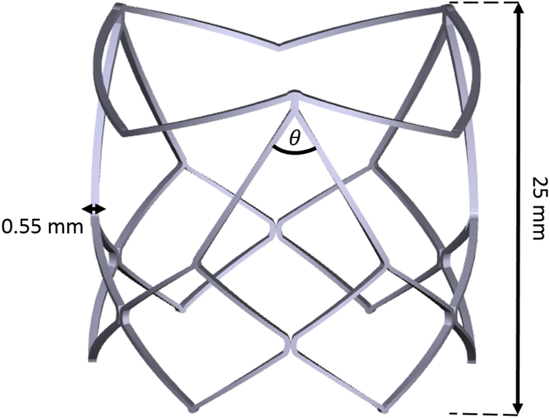
The polymeric transcatheter aortic valve was manufactured in house, as an assembly of an interpenetrated network of Hyaluronan (HA) and linear low density polyethylene (LLDPE) for the valve leaflets and a cobalt chromium (CoCr-MP35N) stent. The stent was designed in 3D CAD software (Solidworks 2018), and laser cut (STI Laser Industries) to be balloon expandable. The balloon expandable stent has a valve diameter is 26mm, and a height of 25mm. A total of 9 non-load bearing polypropylene sutures were used to attach the polymer leaflets to the stent frame to fix their position during crimping. Major features of the CoCr stent design include two distinct rows of diamond shaped structures, where the bottom row is comprised of 6 uniform diamond shaped structures and the top row is comprised of three larger diamond shaped structures with a 60 degree angle, and 3 “V” shaped structures connecting them as shown in Figure 1. The 3 tips of the larger diamond shaped structures are the stent posts, and the “V” shaped structures serve to keep the native aortic valve leaflets from interfering with the functionality of the polymeric leaflets once implanted in the native aortic root. Another unique feature of this stent design is that the polymeric leaflets are attached outside of the stent, rather than being sutured to the inside, and fold under the “V” shaped structures to form the leaflets. A leaflet arch length (h/D) of 0.115 as described in Yousefi et. al.[36] was used for this valve.
Figure 1.
3D CAD model of cobalt chromium transcatheter stent frame, detailing stent thickness(0.55 mm), profile(25 mm), and major frame angle (θ=60°)
2.2. Leaflets’ materials
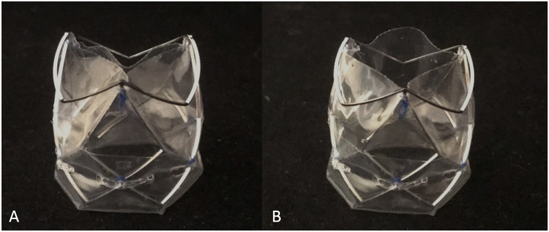
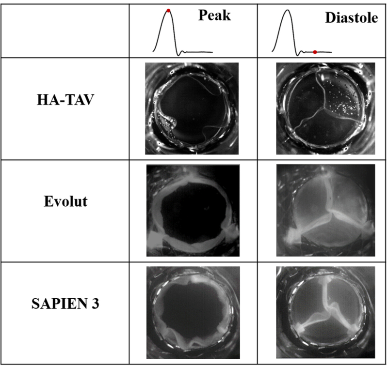
The polymeric leaflets were cut from sheets of interpenetrated networks of HA and LLDPE. Hyaluronan is a highly hydrophilic and anionic molecule, essential to the extracellular matrix of human heart valves[37]. It has been shown to be non-toxic, biodegradable, and non-immunogenic and is therefore highly suitable for blood contacting applications [19, 38, 39]. One advantage of HA is that the molecule has extraordinary potential to be chemically modified, as a way to control its degradation and mechanical properties, as in an interpenetrating network. 80 μm thick polymeric sheets were blow-molded by Flex-Pack Engineering, Inc. (Union-town,OH) from LLDPE resin (Dowlex 2056; Dow Chemical Company, Edegem, Belgium) and then a swelling process was used to form an interpenetrated network (IPN), where two polymers are combined at the molecular level, with HA. This method of introducing HA to the LLDPE has been shown to improve the ability of the two polymers to remain intact, as the polymers in an IPN cannot be separated unless chemical bonds are broken[40] [41]. The HA IPN has shown to be much more durable than surface treatments (such as heparin) that reduce platelet adhesion and improve hemocompatability [20, 42, 43] making it a promising material for prosthetic heart valve leafletsas anticoagulation therapy will not be necessary. Additional details of the manufacturing process and details of the desirable material properties of HA-LLDPE including high yield tensile and tear strengths can be found in previous works[19, 44–46]. Photographs of the valve are shown in Figure 2.
Figure 2.
A. HA-TAV profile of stent frame and semi-closed leaflet position B. HA-TAV profile so stent frame and open leaflet position
2.3. Hemodynamic Parameters
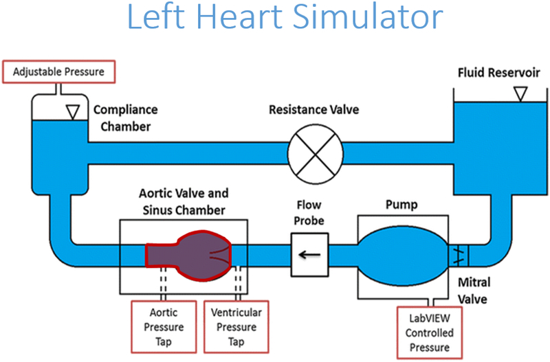
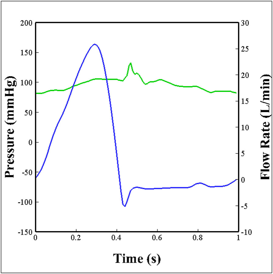
The hemodynamic performance of a polymeric TAV was compared against two of the leading commercially available transcatheter valves of comparable sizes, a 26mm Medtronic Evolut (Minneapolis, Minnesota) and a 26mm Edwards SAPIEN 3 (Irvine, California). The three valves were inserted into an aortic root model of physiological size and connected to an experimental pulse duplicator left heart flow simulator, shown in Figure 3, that is capable of creating pulsatile flow conditions under physiological pressure (120/80 mmHg), heart rate (60 bpm), and cardiac output (5 L/min) as previously described [47–54]. A working fluid of 60/40 water to glycerin (99% pure glycerin) was used to provide density and kinematic viscosity comparable to blood, at 1060 kg/m3 and 3.5 ·10−6 m2/s respectively. Aortic and ventricular pressure as well as flow rate were collected at a sampling frequency of 100 Hz for 60 consecutive cardiac cycles. The aortic flow and pressure that were imposed on the valve are shown in Figure 4, where the flow and pressure have been ensemble averaged over 60 cardiac cycles. Valve leaflet motion was recorded with en-face high speed imaging collected at 1000 frames per second throughout the cardiac cycle. From these data, effective orifice area (EOA), regurgitant fraction (RF), and pinwheeling index (PI) were computed for each of the valve types.
Figure 3.
Schematic of left heart flow simulator
Figure 4.
Aortic flow (blue) and pressure (green) conditions that the valves were subject to over one cardiac cycle.
2.3.1. Effective Orifice Area (EOA)
The effective orifice area (EOA) is a common parameter that assesses valve performance through the quantification of valve stenosis. It is a measurement of the effective jet area during the valve opening phase of the cardiac cycle[55]. EOA was computed from the Gorlin relation:
| (1) |
Where Qrms is the root mean square aortic valve flow rate (cm3/s) and ΔP is the mean pressure drop (mmHg) over the full cardiac cycle.
2.3.2. Regurgitant Fraction (RF)
Regurgitant fraction (RF) is a second common parameter that is used to assess valve performance. It represents the ratio of the closing (CV) and leakage volume (LV) to the forward flow volume (FV). A higher performing valve would demonstrate a low regurgitant fraction (≤ 15%)[56].
| (2) |
2.3.3. Pinwheeling Index (PI)
The pinwheeling index (PI) measures the twisting extent of the leaflets upon closure[54]. High pinwheeling indices have been shown to be linked with decreased leaflet durability[57–59]. PI is computed from still frames of high-speed imaging during valve closing phase as follows:
| (3) |
where Lactual represents the actual length of the free edge of a leaflet, and Lideal represents the shortest distance between the post and central coaptation region, as previously described by Midha et al.[60].
2.4. Particle Image Velocimetry (PIV)
Particle image velocimetry (PIV) was performed to visualize and evaluate the flow velocity field through the valves and to identify turbulence characteristics. Briefly, the flow of interest was seeded with florescent PMMA-Rhodamine B particles (average diameter ~10 μm) and illuminated by a thin laser sheet created with a double pulsed neodymium-doped yitrium lithium fluoride (Nd-YLF) solid state laser coupled with spherical and cylindrical lenses. Time-resolved recordings were acquired at spatial and temporal resolutions of 0.037 mm/pixel and 1000 Hz respectively. 250 repetitions of phase locked measurements were recorded for acceleration, peak, deceleration, and diastolic phases of the cardiac cycle. DaVis PIV software (DaVis 7.2; Lavision, Gӧttingen, Germany) used for all image post processing. More details of PIV techniques can be found elsewhere[1, 50–53, 61].
2.4.1. Vorticity Calculations
Vorticity is the curl of the velocity field and therefore is useful to visualize both rotational blood shearing and turbulence. High vorticity regions along the axis perpendicular to the plane indicate shear and rotation of the fluid particles[54]. Vorticity was computed as follows:
| (4) |
Where ωzis the vorticity component with units of s−1; Vx and Vy are the x and y components of the velocity with units of m/s.
2.4.2. Principal Reynold’s Shear Stress (RSS)
Large Reynold’s shear stress (RSS) is an indicator of high turbulence and has been widely correlated with increasing likelihood of blood and endothelial damage after implantation of heart valve prostheses[26, 62]. Principal RSS is a statistical quantity that measures the shear stress between fluid layers when particles decelerate or accelerate while changing direction [63] and is calculated as:
| (5) |
Where ρis the density of the working fluid (kg/m3) and u′ and V′ are the instantaneous velocity fluctuations in the x and y directions respectively (m/s). Equation (5) implicitly assumes no out-of-plane component of instantaneous velocity, w’, and can be considered as a lower bound for the principle RSS [64].
The principal RSS was calculated for each spatial location downstream the valve and binned by RSS value frequency. Each bin was normalized to the maximum number of counts in any one bin, and this normalized frequency of principal RSS values was plotted.
2.5. Statistical Analysis
Statistical analysis in this study was performed using JMP Pro version 13.0.0 (SAS Institute Inc, Cary, NC). All data are presented as mean ± standard error. A non-parametric comparison of means was performed to compare the mean hemodynamic parameters and a p-value of p < .05 was considered statistically significant. Analyses were performed over 60 replicates.
3. Results
3.1. Hemodynamic Assessment
Hemodynamic parameters obtained from the flow and pressure data for each valve were given in Table 1. The HA-TAV had an EOA of 2.08 ± 0.04 cm2, within one standard deviation of the leading valve, SAPIEN 3 at 2.1 ± 0.025 cm2, through their means were significantly different (P < 0.001). Likewise, the HA-TAV had an increased effective orifice area as compared to the Evolut 1.8 ± 0.036 cm2, with a significance of P < 0.001. The RF of the HA-TAV (11.23 ± 0.55 %) is lower in comparison to the Evolut (15.74 ± 0.73 %) (P < 0.05) and slightly higher than the SAPIEN 3 (10.92 ± 0.11 %) (P < 0.05), putting it well within the range of the two leading commercially available valves.
Table 1.
Measured hemodynamic parameters of each valve
| EOA (cm2) | RF (%) | Pinwheeling Index | |
|---|---|---|---|
| HA-TAV | 2.08±0.04 | 11.23±0.55 | 0.0456±0.03 |
| Evolut | 1.80±0.036 | 15.74±0.73 | 0.122±0.045 |
| SAPIEN 3 | 2.10±0.025 | 10.92±0.11 | 0.366±0.067 |
3.2. Pinwheeling
The En-face views of valve opening and closing at peak systole and mid-diastole are shown for each valve in Figure 5 and in supplementary Video 1. At peak systole, the Evolut and SAPIEN 3 are maximally open, with symmetrical orifices, while the HA-TAV is non-symmetrical and non-circular. Visual inspection of the images shows that the SAPIEN 3 has the largest twisting in the coaptation region, followed by the Evolut and then the HA-TAV. This is in accordance with the values reported in Table 1, where the PI was significantly decreased (P < 0.001) for the HA-TAV (0.0456 ± 0.03) as compared to the Evolut (0.122 ± 0.045) and SAPIEN 3 (0.366 ± 0.067).
Figure 5.
En-face views of each valve at peak systole and mid diastole
3.3. Velocity Vector Field and Vorticity Contours
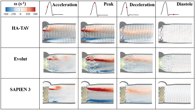
Phase averaged velocity vector fields and corresponding vorticity contours are shown in Figure 6 at four time points in the cardiac cycle, namely, acceleration, peak systole, deceleration and diastole, which are denoted by a red dot along the representative aortic flow curve. Bright red and blue contours represent the shear layers, which correspond to the jet boundaries. The distance between the shear layers represent the width of the jet through the valve.
Figure 6.
Phase averaged velocity vectors and vorticity contours throughout the cardiac cycle
The maximum value of velocity for the HA-TAV was 1.56 m/s during acceleration, 1.94 at peak systole, and 1.03 at deceleration phase. In comparison, the Evolut’s maximum velocity at acceleration phase was decreased (1.00 m/s), increased to reach 2.45 m/s at peak systole, and then 1.37 m/s during deceleration. The SAPIEN 3 velocity increased from 0.86 m/s during acceleration, 2.10 m/s at peak systole, and reached 0.94 m/s during deceleration. The velocity during diastole was 0.17 m/s for the HA-TAV, and 0.19 m/s for both the Evolut and SAPIEN 3.
Developed shear layers occur sooner during acceleration phase in the HA-TAV as compared to the Evolut and SAPIEN 3. At peak systole, the shear layers were thinner with the HA-TAV compared to the Evolut and SAPIEN, and were characterized by lower vorticity magnitudes 5 mm downstream the valve with the HA-TAV approximately half the magnitude of the SAPIEN 3 and approximately 4/5th of the magnitude of the Evolut. At the deceleration phase, the distance between the shear layers was significantly reduced for the HA-TAV, and only very slightly for the Evolut and SAPIEN 3, showing that the jet narrows sooner in systole for the HA-TAV.
3.4. Reynolds Shear Stress (RSS)
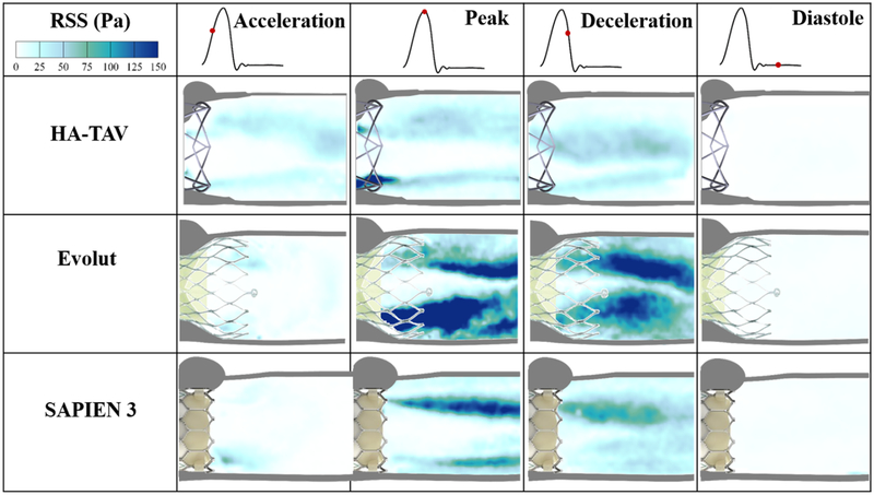
Figure 7 shows the principal Reynolds shear stress (RSS) at acceleration, peak, deceleration and diastolic phases of the cardiac cycle for each valve. RSS is an important indicator of platelet activation due to the turbulent fluctuations of the blood velocity[26–28, 53, 54, 62, 65].
Figure 7.
Phase averaged Principle Reynolds shear stresses (RSS) throughout the cardiac cycle
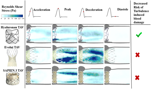
For each valve, the highest values of RSS were present at peak systole. In comparison to the Evolut and SAPIEN 3, the HA-TAV had a significantly smaller region in which higher RSS values (>10 Pa) were present, concentrated near the stent frame alone. While in the HA-TAV and SAPIEN 3 the majority of the RSS had dissipated by the deceleration time point, the Evolut demonstrated slower dissipation of these stresses. This observation is clearly demonstrated in the distribution plots of the principal Reynolds shear stresses at acceleration, peak and deceleration in Figure 8. During acceleration, there is a single peak of the normalized frequency curve for the HA-TAV and the two commercial valves. The Evolut has the widest peak, indicating that it holds the highest number of higher RSS values. During peak systole, the HA-TAV has a similar frequency profile as it did in acceleration. The Evolut does not reach 0 frequency as quickly, and the profile of the frequency curve is not smooth indicating regions of high values of increased RSS, while the SAPIEN 3 is somewhat smoother, reaching 0 frequency at a lower value of RSS than for the Evolut. At deceleration, the frequency profile for the HA-TAV is no longer smooth, but still reaches 0 at a lower RSS value than the two commercially available valves. The Evolut has a wide second peak at higher RSS values, and the SAPIEN 3 has a sharp second peak at lower RSS values.
Figure 8.
Normalized frequency of Principal Reynolds shear stress at the defined phases in the cardiac cycle
4. Discussion
The potential of the novel HA-TAV was investigated in this in vitro study through (1) evaluating hemodynamic parameters (2) assessing velocity and vorticity and (3) analyzing turbulence characteristics through calculating RSS.
4.1. Hemodynamic Assessment and Pinwheeling
The effective orifice area of the HA-TAV was comparable to the SAPIEN 3, and both were larger than the Evolut. One reason for this difference may be that the HA-TAV and SAPIEN 3 are balloon-expandable, while the Evolut is self-expanding. Balloon expandable valves are known to contribute to reduced pressure gradients in TAVs and larger orifice areas, due to the radial force of the balloon anchoring into the aortic root[1, 66, 67]. The improved effective orifice area could also likely be due to the polymeric material and difference in the HA-TAV stent design that allows the leaflets to fold out beyond the confinement of the inner-diameter of the stent producing a unique three dimensional leaflet surface geometry during the forward flow phase. This leaflet surface geometry likely produces some out of plane component of the main jet, which could induce swirling flows and increase effective orifice areas. A particle streak video (Supplementary Video 2) of the HA-TAV show evidence of these potential swirling flows as compared to that for the Evolut and SAPIEN 3.
Regurgitant fraction is of major importance in the development of novel transcatheter aortic valves, as a high RF puts additional load on the heart to pump adequate blood supply to the rest of the body[52]. Also, additional consideration should be given to the development of a non-physiological backwards flow jet that can induce platelet activation and hemolysis[36, 68–71]. RF of the HA-TAV falls within the levels of the SAPIEN 3 and Evolut, marking it as comparable to these two commercially available valves and trace with regards to the standards presented by Nishimura et. al.[72]
The pinwheeling index of the HA-TAV is significantly decreased in comparison to the Evolut and SAPIEN 3. This is likely an effect of the leaflet design, with arched profiles modified from Yousefi et. al.[36] that allow for there to be a balance between optimal coaptation area and minimized PI to ensure central gap closure and enhance leaflet durability respectively.
The regurgitant fractions obtained in this study for the HA-TAV were found to be lower than those obtained with TRISKELE-26 valve (19.3%) while the effective orifice area was found to be higher for the HA-TAV as compared to the TRISKELE-26 (1.9 cm2) [31].
4.2. Velocity and Vorticity
The increased velocity for the HA-TAV during the acceleration phase as compared to Evolut and SAPIEN 3 is likely due to a combination of the delay in opening of the polymeric leaflets (Supplementary Video 1), and the geometry of the orifice that is present throughout the cardiac cycle. The flexural properties of material used for prosthetic heart valve leaflets are highly important to heart valve design, as it has been shown that leaflet bending plays a critical role in bioprosthetic heart valve and function[73]. The smaller orifice produces higher jet velocities at this stage. However, at peak systole, the HA-TAV has reached max opening and shows decreased max jet velocities than for the Evolut and SAPIEN 3.
In the HA-TAV, the shear layers are significantly diminished in approximately half of the distance downstream of the valve outlet as they are for the Evolut and SAPIEN 3, with much lower magnitudes in as little as 5 mm from the outlet. This decrease in vorticity fluctuation is indicative of a decrease in turbulence (and therefore energy loss). This decrease in in vorticity and in turbulence may be due to the leaflet geometry that could induce a slightly out of plane component of the main jet giving way to swirling flows. In the deceleration phase, it is clear that the HA-TAV begins to close sooner after reaching max opening than the two tissue valves, as seen by the sudden diminishing of distance between shear layers (jet width) at this time point.
4.3. Reynolds’ Shear Stress
RSS magnitudes have an important role in determining the biocompatibility of a valve prosthesis because they can indicate regions of probable platelet activation from turbulent fluctuations of the blood velocity[26–28, 65, 74]. Previous in vitro studies attempted to set some thresholds that mark the onset of platelet activation[51]. The critical shear stress levels for hemolysis and platelet lysis under physiological exposure times have been shown to be between 150–400 Pa [25]. However, thresholds are not yet well-established, and the characterization of turbulent stress is still controversial[51].
At peak systole, where RSS was highest for each valve, it is clear that the HA-TAV has the least frequency of high RSS values that increase the likelihood of platelet activation (>100 Pa)[75–77]. This is likely due to the stent frame design that is both low in profile, and has a decreased number of “grid” like structures that have been shown to increase turbulence, unsteadiness, and skewness of velocity fluctuation[53, 54, 78–80]. The stent design aspects therefore also explain the increase in RSS of the Evolut compared to the SAPIEN 3, as the Evolut has an increase profile (protrudes further into the aorta) which increases the meshed flow contacting areas[54]. The leaflet flutter seen in the two tissue valves are also known to cause high cycle-to-cycle variability in the flow, which could have contributed to the increased frequency of high Reynolds shear stress[81]. While each valve demonstrated a max RSS value exceeding 100 Pa at peak systole, at every cardiac phase the HA-TAV had decreased frequency of high RSS values suggesting that platelet activation and therefore thrombus formation is least likely to occur in this valve.
5. Polymeric TAVs as an alternative for bioprosthetic TAVs
While current bioprosthetic TAVRs have made a less invasive heart valve replacement surgery possible, there are still major concerns about their long term durability, especially when the life expectancy of a patient exceeds the ‘proven’ good midterm durability of 5–7 years[82]. The biological tissue used in all commercially available TAVs is prone to structural valve degeneration, which has been estimated to occur in over 50% of patients receiving transcatheter aortic valve replacements within 8 years[83]. Factors associated with complications post-TAVR such as subclinical valve thrombosis have been detected in 10% to 15% of patients receiving bioprosthetic TAVs[84], and introducing anticoagulation therapy poses its own severe risks[85]. Now that TAVR is approved for low risk patients, it is therefore crucial and urgent to develop not only a substitute of a leaflet material but rather a novel valve as a whole presenting excellent hemodynamic performance from appropriate interaction between leaflet and stent, and leaflet-stent and blood. The data presented herein demonstrate the hemodynamic potential of a polymeric based TAVR device to change the future of TAV replacement therapy. In-vivo data are ongoing to validate these in-vitro data.
6. Summary
The hemodynamic performance and turbulence of a novel polymeric transcatheter valve, the HA-TAV, were compared against two same size leading commercially available transcatheter valves, the Medtronic Evolut and Edwards SAPIEN 3 in-vitro. Resulting measurements of hemodynamic parameters including EOA, RF, and PI have demonstrated that the HA-TAV exceeds baseline hemodynamic requirements and is directly comparable to the leading valves, while the results of turbulent flow characterization in the HA-TAV show improvement over the leading commercially available valves. Ongoing accelerated fatigue testing and in-vivo studies strongly indicate the potential for a polymeric valve to be an alternative solution to the prosthetic valves currently used in TAVR procedures.
7. Limitations
Though we do not expect valve to valve variability in either of the commercially available valves, limited availability of the TAVs that were used has limited the study to n=1 of each valve type. Further, valve hemodynamics performance and turbulence characteristics are not the only factors used to assess valve performance and readiness for in vivo use and in the current state additional studies would be needed to claim that this valve is an alternative to those that are commercially available. Of these additional studies, accelerated fatigue testing is necessary to evaluate the expected long term durability of the sutured polymer and novel stent frame. Further studies are needed to comprehensively assess the mechanism by which the HA-TAV demonstrated superior hemodynamics.
Supplementary Material
Supplementary Video 1. En-face views of each valve throughout the cardiac cycle
Supplementary Video 2. Particle streak videos of each valve throughout the cardiac cycle
Funding:
The research done was partly supported by National Institutes of Health (NIH) under Award Number R01HL119824, R01HL13550501A1, and R03EB01425502 and the American Heart Association (AHA) under Award Number 19POST34380804.
Abbreviations
- TAVR
Transcatheter aortic valve replacement
- HA
Hyaluronan
- PVL
Paravalvular leakage
- HA-TAV
Hyaluronan enhanced transcatheter aortic valve
- LLDPE
Linear low-density polyethylene
- EOA
Effective orifice area
- RF
Regurgitant fraction
- PI
Pinwheeling index
- PIV
Partical image velocimetry
- CV
Closing volume
- LV
Leakage volume
- FV
Forward flow volume
- RSS
Reynolds shear stress
Footnotes
Publisher's Disclaimer: This is a PDF file of an unedited manuscript that has been accepted for publication. As a service to our customers we are providing this early version of the manuscript. The manuscript will undergo copyediting, typesetting, and review of the resulting proof before it is published in its final citable form. Please note that during the production process errors may be discovered which could affect the content, and all legal disclaimers that apply to the journal pertain.
Conflict of Interest: Dr. Dasi reports having two patent applications on novel surgical and transcatheter valves. He also has a patent issued on vortex generators on heart valves and a patent application on super hydrophobic vortex generator enhanced mechanical heart valves. No other conflicts were reported.
References
- 1.Dasi LP, et al. , On the Mechanics of Transcatheter Aortic Valve Replacement. Annals of Biomedical Engineering, 2017. 45(2): p. 310–331. [DOI] [PMC free article] [PubMed] [Google Scholar]
- 2.Tice JA, Sellke FW, and Schaff HV, Transcatheter aortic valve replacement in patients with severe aortic stenosis who are at high risk for surgical complications: Summary assessment of the California Technology Assessment Forum. Journal of Thoracic and Cardiovascular Surgery, 2014. 148(2): p. 482–491.e6. [DOI] [PubMed] [Google Scholar]
- 3.Kheradvar A, et al. , Emerging trends in heart valve engineering: Part II. Novel and standard technologies for aortic valve replacement. Annals of biomedical engineering, 2015. 43(4): p. 844–857. [DOI] [PubMed] [Google Scholar]
- 4.Mylotte D and Piazza N, Transcatheter aortic valve replacement failure: déjà vu ou jamais vu? 2015, Am Heart Assoc. [DOI] [PubMed] [Google Scholar]
- 5.Dasi LP, et al. , On the mechanics of transcatheter aortic valve replacement. Annals of biomedical engineering, 2017. 45(2): p. 310–331. [DOI] [PMC free article] [PubMed] [Google Scholar]
- 6.Makkar RR, et al. , Possible Subclinical Leaflet Thrombosis in Bioprosthetic Aortic Valves. New England Journal of Medicine, 2015. 373(21): p. 2015–2024. [DOI] [PubMed] [Google Scholar]
- 7.Mylotte D and Piazza N, Transcatheter Aortic Valve Replacement Failure Deja vu ou Jamais vu? Circulation-Cardiovascular Interventions, 2015. 8(4): p. 4. [DOI] [PubMed] [Google Scholar]
- 8.Kheradvar A, et al. , Emerging trends in heart valve engineering: Part IV. Computational modeling and experimental studies. Annals of biomedical engineering, 2015. 43(10): p. 2314–2333. [DOI] [PubMed] [Google Scholar]
- 9.Foroutan F, et al. , Prognosis after surgical replacement with a bioprosthetic aortic valve in patients with severe symptomatic aortic stenosis: systematic review of observational studies. BMJ, 2016. 354. [DOI] [PMC free article] [PubMed] [Google Scholar]
- 10.Daubert MA, et al. , Long-Term Valve Performance of TAVR and SAVR: A Report From the PARTNER I Trial. JACC: Cardiovascular Imaging, 2017. 10(1): p. 15–25. [DOI] [PubMed] [Google Scholar]
- 11.Haussig S, et al. , TCT-790 Long-term follow-up after transcatheter aortic valve implantation and durability of transcatheter aortic valves - results of a prospective single-center registry. Journal of the American College of Cardiology, 2017. 70(18 Supplement): p. B269. [Google Scholar]
- 12.Pathak CP, et al. , Treatment of bioprosthetic heart valve tissue with long chain alcohol solution to lower calcification potential. J Biomed Mater Res A, 2004. 69(1): p. 140–4. [DOI] [PubMed] [Google Scholar]
- 13.Hetzer R, et al. , Thrombosis and Degeneration of Hancock Valves: Clinical and Pathological Findings. The Annals of Thoracic Surgery, 1978. 26(4): p. 317–322. [DOI] [PubMed] [Google Scholar]
- 14.Kiefer P, et al. , Crimping May Affect the Durability of Transcatheter Valves: An Experimental Analysis. The Annals of Thoracic Surgery, 2011. 92(1): p. 155–160. [DOI] [PubMed] [Google Scholar]
- 15.Alavi SH, Groves EM, and Kheradvar A, The Effects of Transcatheter Valve Crimping on Pericardial Leaflets. The Annals of Thoracic Surgery, 2014. 97(4): p. 1260–1266. [DOI] [PubMed] [Google Scholar]
- 16.Roe BB, Late follow-up studies on flexible leaflet prosthetic valves. Journal of Thoracic and Cardiovascular Surgery, 1969. 58: p. 59–61. [PubMed] [Google Scholar]
- 17.Ghanbari H, et al. , Polymeric heart valves: new materials, emerging hopes. Trends in Biotechnology, 2009. 27(6): p. 359–367. [DOI] [PubMed] [Google Scholar]
- 18.Kannan RY, et al. , Polyhedral oligomeric silsesquioxane nanocomposites: The next generation material for biomedical applications. Accounts of Chemical Research, 2005. 38(11): p. 879–884. [DOI] [PubMed] [Google Scholar]
- 19.Prawel DA, et al. , Hemocompatibility and Hemodynamics of Novel Hyaluronan–Polyethylene Materials for Flexible Heart Valve Leaflets. Cardiovascular Engineering and Technology, 2014. 5(1): p. 70–81. [DOI] [PMC free article] [PubMed] [Google Scholar]
- 20.Simon-Walker R, et al. , Hemocompatibility of hyaluronan enhanced linear low density polyethylene for blood contacting applications. J Biomed Mater Res B Appl Biomater, 2018. 106(5): p. 1964–1975. [DOI] [PMC free article] [PubMed] [Google Scholar]
- 21.Hatoum H, et al. , An in vitro evaluation of turbulence after transcatheter aortic valve implantation. The Journal of Thoracic and Cardiovascular Surgery, 2018. 156(5): p. 1837–1848. [DOI] [PMC free article] [PubMed] [Google Scholar]
- 22.Hatoum H, Maureira P, and Dasi LP, A turbulence in-vitro assessment of ON-X and St. Jude Medical prostheses. The Journal of Thoracic and Cardiovascular Surgery, 2019. [DOI] [PMC free article] [PubMed] [Google Scholar]
- 23.Movafaghi S, et al. , Hemocompatibility of superhemophobic titania surfaces. Advanced healthcare materials, 2017. 6(4): p. 1600717. [DOI] [PubMed] [Google Scholar]
- 24.Dasi LP, et al. , Fluid mechanics of artificial heart valves. Clin Exp Pharmacol Physiol, 2009. 36(2): p. 225–37. [DOI] [PMC free article] [PubMed] [Google Scholar]
- 25.Quantitation of the turbulent stress distribution downstream of normal, diseased and artificial aortic valves in humans. European Journal of Cardio-Thoracic Surgery, 1992. 6(11): p. 609–617. [DOI] [PubMed] [Google Scholar]
- 26.Giersiepen M, et al. , Estimation of shear stress-related blood damage in heart valve prostheses - in vitro comparison of 25 aortic valves. International Journal of Artificial Organs, 1990. 13(5): p. 300–306. [PubMed] [Google Scholar]
- 27.Hanle DD, et al. , Turbulence downstream from the Ionescu-Shiley bioprosthesis in steady and pulsatile flow. Medical & Biological Engineering & Computing, 1987. 25(6): p. 645–649. [DOI] [PubMed] [Google Scholar]
- 28.Jones SA, A relationship between reynolds stresses and viscous dissipation: Implications to red cell damage. Annals of Biomedical Engineering, 1995. 23(1): p. 21–28. [DOI] [PubMed] [Google Scholar]
- 29.Popma JJ, et al. , Transcatheter Aortic-Valve Replacement with a Self-Expanding Valve in Low-Risk Patients. New England Journal of Medicine. 0(0): p. null. [DOI] [PubMed] [Google Scholar]
- 30.Mack MJ, et al. , Transcatheter Aortic-Valve Replacement with a Balloon-Expandable Valve in Low-Risk Patients. New England Journal of Medicine. 0(0): p. null. [DOI] [PubMed] [Google Scholar]
- 31.Rahmani B, et al. , In Vitro Hydrodynamic Assessment of a New Transcatheter Heart Valve Concept (the TRISKELE). Journal of Cardiovascular Translational Research, 2017. 10(2): p. 104–115. [DOI] [PMC free article] [PubMed] [Google Scholar]
- 32.Rotman OM, et al. , Novel Polymeric Valve for Transcatheter Aortic Valve Replacement Applications: In Vitro Hemodynamic Study. Annals of Biomedical Engineering, 2019. 47(1): p. 113–125. [DOI] [PMC free article] [PubMed] [Google Scholar]
- 33.Wang Q, et al. , In-vivo assessment of a novel polymer (SIBS) trileaflet heart valve. J Heart Valve Dis, 2010. 19(4): p. 499–505. [PubMed] [Google Scholar]
- 34.Claiborne TE, et al. , In Vitro Evaluation of a Novel Hemodynamically Optimized Trileaflet Polymeric Prosthetic Heart Valve. Journal of Biomechanical Engineering, 2013. 135(2): p. 021021–021021–8. [DOI] [PMC free article] [PubMed] [Google Scholar]
- 35.Daebritz SH, et al. , New flexible polymeric heart valve prostheses for the mitral and aortic positions. Heart Surg Forum, 2004. 7(5): p. E525–32. [DOI] [PubMed] [Google Scholar]
- 36.Yousefi A, Bark DL, and Dasi LP, Effect of Arched Leaflets and Stent Profile on the Hemodynamics of Tri-Leaflet Flexible Polymeric Heart Valves. Annals of Biomedical Engineering, 2017. 45(2): p. 464–475. [DOI] [PMC free article] [PubMed] [Google Scholar]
- 37.Simon-Walker R, et al. , Hemocompatibility of hyaluronan enhanced linear low density polyethylene for blood contacting applications. Journal of Biomedical Materials Research Part B: Applied Biomaterials, 2017. 106(5): p. 1964–1975. [DOI] [PMC free article] [PubMed] [Google Scholar]
- 38.Camci-Unal G, et al. , Surface-modified hyaluronic acid hydrogels to capture endothelial progenitor cells. Soft matter, 2010. 6(20): p. 5120–5126. [DOI] [PMC free article] [PubMed] [Google Scholar]
- 39.Laurent TC, Laurent UB, and Fraser JRE, The structure and function of hyaluronan: an overview. Immunology and cell biology, 1996. 74(2): p. A1. [DOI] [PubMed] [Google Scholar]
- 40.Smith CR, et al. , Transcatheter versus surgical aortic-valve replacement in high-risk patients. New England Journal of Medicine, 2011. 364(23): p. 2187–2198. [DOI] [PubMed] [Google Scholar]
- 41.Jenkins A, et al. , Glossary of basic terms in polymer science (IUPAC Recommendations 1996). Pure and applied chemistry, 1996. 68(12): p. 2287–2311. [Google Scholar]
- 42.Lagergre H, Olsson P, and Swedenbo J, INHIBITED PLATELET ADHESION - NON-THROMBOGENIC CHARACTERISTIC OF A HEPARIN-COATED SURFACE. Surgery, 1974. 75(5): p. 643–650. [PubMed] [Google Scholar]
- 43.Olsson P, et al. , PREVENTION OF PLATELET-ADHESION AND AGGREGATION BY A GLUTARDIALDEHYDE-STABILIZED HEPARIN SURFACE. Thrombosis and Haemostasis, 1977. 37(2): p. 274–282. [PubMed] [Google Scholar]
- 44.Dean H, Development of a Biopoly™ Micro-composite For Use In Prosthetic Heart Valve Replacements. Fort Collins: Colorado State University, Master of Science, 2011. [Google Scholar]
- 45.James SP, Zhang M, and Beauregard G, Outer layer having entanglement of hydrophobic polymer host and hydrophilic polymer guest. 2010, Google Patents.
- 46.Zhang M, James SP, and Rentfrow E, The effect of IPN surface modification on the mechanical properties of UHMWPE. Biomed Sci Instrum, 2001. 37: p. 7–12. [PubMed] [Google Scholar]
- 47.Hatoum H, et al. , Aortic sinus flow stasis likely in valve-in-valve transcatheter aortic valve implantation. Journal of Thoracic and Cardiovascular Surgery, 2017. 154(1): p. 32–43.e1. [DOI] [PMC free article] [PubMed] [Google Scholar]
- 48.Hatoum H and Dasi L, Sinus Hemodynamics in Representative Stenotic Native Bicuspid and Tricuspid Aortic Valves: An In-Vitro Study. Fluids, 2018. 3(3): p. 56. [Google Scholar]
- 49.Hatoum H, et al. , Impact of patient-specific morphologies on sinus flow stasis in transcatheter aortic valve replacement: An in vitro study. The Journal of thoracic and cardiovascular surgery, 2018. [DOI] [PMC free article] [PubMed] [Google Scholar]
- 50.Hatoum H, et al. , Effect of severe bioprosthetic valve tissue ingrowth and inflow calcification on valve-in-valve performance. Journal of Biomechanics, 2018. 74: p. 171–179. [DOI] [PMC free article] [PubMed] [Google Scholar]
- 51.Hatoum H, et al. , Implantation Depth and Rotational Orientation Effect on Valve-in-Valve Hemodynamics and Sinus Flow. The Annals of thoracic surgery, 2018. [DOI] [PMC free article] [PubMed] [Google Scholar]
- 52.Hatoum H, et al. , Sinus hemodynamics variation with tilted transcatheter aortic valve deployments. Annals of biomedical engineering, 2018: p. 1–10. [DOI] [PMC free article] [PubMed] [Google Scholar]
- 53.Hatoum H, Heim F, and Dasi LP, Stented valve dynamic behavior induced by polyester fiber leaflet material in transcatheter aortic valve devices. Journal of the mechanical behavior of biomedical materials, 2018. 86: p. 232–239. [DOI] [PMC free article] [PubMed] [Google Scholar]
- 54.Hatoum H, et al. , An in vitro evaluation of turbulence after transcatheter aortic valve implantation. The Journal of Thoracic and Cardiovascular Surgery, 2018. [DOI] [PMC free article] [PubMed] [Google Scholar]
- 55.Dasi LP, et al. , FLUID MECHANICS OF ARTIFICIAL HEART VALVES. Clinical and experimental pharmacology & physiology, 2009. 36(2): p. 225–237. [DOI] [PMC free article] [PubMed] [Google Scholar]
- 56.Standardization, I.O.f., Cardiovascular implants in Cardiac valve prostheses. 2016. [Google Scholar]
- 57.Gunning PS, et al. , Total ellipse of the heart valve: the impact of eccentric stent distortion on the regional dynamic deformation of pericardial tissue leaflets of a transcatheter aortic valve replacement. Journal of The Royal Society Interface, 2015. 12(113). [DOI] [PMC free article] [PubMed] [Google Scholar]
- 58.Martin C and Sun W, Simulation of long-term fatigue damage in bioprosthetic heart valves: effects of leaflet and stent elastic properties. Biomechanics and Modeling in Mechanobiology, 2014. 13(4): p. 759–770. [DOI] [PMC free article] [PubMed] [Google Scholar]
- 59.Doose C, et al. , Valve-in-valve outcome: design impact of a pre-existing bioprosthesis on the hydrodynamics of an Edwards Sapien XT valve. Eur J Cardiothorac Surg, 2017. 51(3): p. 562–570. [DOI] [PubMed] [Google Scholar]
- 60.Midha PA, et al. , Valve Type, Size, and Deployment Location Affect Hemodynamics in an In Vitro Valve-in-Valve Model. JACC: Cardiovascular Interventions, 2016. 9(15): p. 1618–1628. [DOI] [PubMed] [Google Scholar]
- 61.Dasi LP, et al. , Passive flow control of bileaflet mechanical heart valve leakage flow. Journal of Biomechanics, 2008. 41(6): p. 1166–1173. [DOI] [PubMed] [Google Scholar]
- 62.Nygaard H, et al. , Two-dimensional color-mapping of turbulent shear stress distribution downstream of two aortic bioprosthetic valves in vitro. J Biomech, 1992. 25(4): p. 429–40. [DOI] [PubMed] [Google Scholar]
- 63.Gunning PS, et al. , An in vitro evaluation of the impact of eccentric deployment on transcatheter aortic valve hemodynamics. Annals of Biomedical Engineering, 2014. 42(6): p. 1195–1206. [DOI] [PubMed] [Google Scholar]
- 64.Hasler D and Obrist D, Three-dimensional flow structures past a bio-prosthetic valve in an in-vitro model of the aortic root. PLOS ONE, 2018. 13(3): p. e0194384. [DOI] [PMC free article] [PubMed] [Google Scholar]
- 65.Schoephoerster RT and Chandran KB, Velocity and turbulence measurements past mitrial valve prostheses in a model left ventricle. Journal of Biomechanics, 1991. 24(7): p. 549–562. [DOI] [PubMed] [Google Scholar]
- 66.Morganti S, et al. , Simulation of transcatheter aortic valve implantation through patient-specific finite element analysis: Two clinical cases. Journal of Biomechanics, 2014. 47(11): p. 2547–2555. [DOI] [PubMed] [Google Scholar]
- 67.Bianchi M, et al. Simulation of Transcatheter Aortic Valve Replacement in patient-specific aortic roots: Effect of crimping and positioning on device performance. in Proceedings of the Annual International Conference of the IEEE Engineering in Medicine and Biology Society, EMBS 2015. [DOI] [PubMed] [Google Scholar]
- 68.Garcia MJ, et al. , Mechanisms of hemolysis with mitral prosthetic regurgitation study using transesophageal echocardiography and fluid dynamic simulation. Journal of the American College of Cardiology, 1996. 27(2): p. 399–406. [DOI] [PubMed] [Google Scholar]
- 69.Maraj R, et al. , Evaluation of hemolysis in patients with prosthetic heart valves. Clinical Cardiology, 1998. 21(6): p. 387–392. [DOI] [PMC free article] [PubMed] [Google Scholar]
- 70.Minniti CP, et al. , Elevated tricuspid regurgitant jet velocity in children and adolescents with sickle cell disease: association with hemolysis and hemoglobin oxygen desaturation. Haematologica, 2009. 94(3): p. 340–347. [DOI] [PMC free article] [PubMed] [Google Scholar]
- 71.Wilson JH, et al. , Severe hemolysis after incomplete mitral valve repair. The Annals of Thoracic Surgery, 1990. 50(1): p. 136–137. [DOI] [PubMed] [Google Scholar]
- 72.Nishimura RA, et al. , 2014 AHA/ACC Guideline for the Management of Patients With Valvular Heart Disease. A Report of the American College of Cardiology/American Heart Association Task Force on Practice Guidelines, 2014. 63(22): p. e57–e185. [DOI] [PubMed] [Google Scholar]
- 73.Sacks MS and Yoganathan AP, Heart valve function: A biomechanical perspective. Philosophical Transactions of the Royal Society B: Biological Sciences, 2007. 362(1484): p. 1369–1391. [DOI] [PMC free article] [PubMed] [Google Scholar]
- 74.Nygaard H, et al. , Two-dimensional color-mapping of turbulent shear stress distribution downstream of two aortic bioprosthetic valves in vitro. Journal of Biomechanics, 1992. 25(4): p. 429–440. [DOI] [PubMed] [Google Scholar]
- 75.Dasi LP, et al. , Fluid mechanics of artificial heart valves. Clinical and Experimental Pharmacology and Physiology, 2009. 36(2): p. 225–237. [DOI] [PMC free article] [PubMed] [Google Scholar]
- 76.Ramstack JM, Zuckerman L, and Mockros LF, Shear-induced activation of platelets. Journal of Biomechanics, 1979. 12(2): p. 113–125. [DOI] [PubMed] [Google Scholar]
- 77.Liu JS, Lu PC, and Chu SH, Turbulence characteristics downstream of bileaflet aortic valve prostheses. Journal of Biomechanical Engineering, 2000. 122(2): p. 118–124. [DOI] [PubMed] [Google Scholar]
- 78.Antohe BV and Lage JL, A general two-equation macroscopic turbulence model for incompressible flow in porous media. International Journal of Heat and Mass Transfer, 1997. 40(13): p. 3013–3024. [Google Scholar]
- 79.Mößner M and Radespiel R, Flow simulations over porous media – Comparisons with experiments. Computers and Fluids, 2017. 154: p. 358–370. [Google Scholar]
- 80.Yang SK and Chung MK, Turbulent flow through spacer grids in rod bundles. Journal of Fluids Engineering, Transactions of the ASME, 1998. 120(4): p. 786–791. [Google Scholar]
- 81.Peacock JA, An in vitro study of the onset of turbulence in the sinus of Valsalva. Circ Res, 1990. 67(2): p. 448–60. [DOI] [PubMed] [Google Scholar]
- 82.Salaun E, et al. , Bioprosthetic aortic valve durability in the era of transcatheter aortic valve implantation. Heart, 2018. 104(16): p. 1323–1332. [DOI] [PubMed] [Google Scholar]
- 83.D D, First look at long-term durability of transcatheter heart valves: assessment of valve function up to 10 years. Presented at: EuroPCR 2016 Paris, France , 2016. [Google Scholar]
- 84.Puri R, Auffret V, and Rodés-Cabau J, Bioprosthetic valve thrombosis. Journal of the American College of Cardiology, 2017. 69(17): p. 2193–2211. [DOI] [PubMed] [Google Scholar]
- 85.Shoeb M and Fang MC, Assessing Bleeding Risk in Patients Taking Anticoagulants. Journal of thrombosis and thrombolysis, 2013. 35(3): p. 312–319. [DOI] [PMC free article] [PubMed] [Google Scholar]
Associated Data
This section collects any data citations, data availability statements, or supplementary materials included in this article.
Supplementary Materials
Supplementary Video 1. En-face views of each valve throughout the cardiac cycle
Supplementary Video 2. Particle streak videos of each valve throughout the cardiac cycle


