Abstract.
X-ray luminescence computed tomography (XLCT) is an emerging hybrid imaging modality which has the potential for achieving both high sensitivity and spatial resolution simultaneously. For the narrow x-ray beam-based XLCT imaging, based on previous work, a spatial resolution of about double the x-ray beam size can be achieved using a translate/rotate scanning scheme, taking step sizes equal to the x-ray beam width. To break the current spatial resolution limit, we propose a scanning strategy achieved by reducing the scanning step size to be smaller than the x-ray beam size. We performed four sets of numerical simulations and a phantom experiment using cylindrical phantoms and have demonstrated that our proposed scanning method can greatly improve the XLCT-reconstructed image quality compared with the traditional scanning approach. In our simulations, by using a fixed x-ray beam size of 0.8 mm, we were able to successfully reconstruct six embedded targets as small as 0.5 mm in diameter and with the same edge-to-edge distances by using a scanning step as small as 0.2 mm which is a 1.6 times improvement in the spatial resolution compared with the traditional approach. Lastly, the phantom experiment further demonstrated the efficacy of our proposed method in improving the XLCT image quality, with all image quality metrics improving as the step size decreased.
Keywords: x-ray luminescence, tomography, medical optics instrumentation
1. Introduction
X-ray luminescence computed tomography (XLCT) is an emerging hybrid molecular imaging modality with promising potential to have both the high molecular sensitivity of optical imaging and the good spatial resolution of x-ray imaging, which cannot be achieved by either modality alone. Since Pratx et al. reported for the first time that narrow-beam selective excitation-based XLCT imaging could image the distribution of phosphor particles,1–3 various institutions have made many attempts to further develop and improve XLCT imaging by developing new imaging systems,1,4–12 building robust reconstruction algorithms,13–15 and designing efficient imaging probes.16–20
Currently, there are two primary types of scanning modes for XLCT imaging. One is the cone beam-based XLCT imaging,9,21,22 in which a conical x-ray beam is used to cover the whole object so that the scanning time is as short as a few seconds. The disadvantage of this approach is that the spatial resolution is compromised because the x-ray beam size is larger and cannot be used for anatomical guidance in the image reconstruction. Another scanning mode is the narrow beam-based XLCT imaging, in which a collimated or focused x-ray beam is used to scan an object sequentially.1,11,12 The narrow beam-based XLCT imaging can have a spatial resolution up to a fraction of a millimeter because the fine beam size can be applied for anatomical guidance in the XLCT reconstruction algorithm.23 The disadvantage is its relatively long scanning time due to the small excitation region, although this can be addressed by using a higher sensitivity optical detector.10,12
In the traditional narrow x-ray beam-based XLCT system design, the fundamental limit of spatial resolution is determined by the beam aperture size.3 From these reports, we know that it is impossible to separate two targets when the x-ray beam size is larger than the target diameter as well as the target edge-to-edge distance (EED). Zhang et al.11 have reported that the spatial resolution of a narrow beam-based XLCT imaging is double the size of the scanning beam diameter. Thus, current efforts to improve the spatial resolution focus on how to obtain a small x-ray beam. There are several approaches to reduce the x-ray beam size. One approach is to focus an x-ray beam with an x-ray optics lens to a fine focal spot. Cong et al.13 proposed a dual cone scanning method with a polycapillary lens, in which the x-ray beam was focused into a spot with a diameter of . Later, Zhang et al.10 built a focused x-ray beam-based XLCT imaging system with a focused beam size of . This method can maximize the intensity of the x-ray energy at the focal point of a dual cone beam. However, the polycapillary lens is expensive and has the drawback that it is very difficult to focus high-energy x-ray photons. The adoption of low-energy x-ray beams (e.g., within the range from 15 to 20 keV) would reduce the x-ray penetration ability, and thus, large objects could be difficult or impossible to image. Another approach is to collimate a conical x-ray beam into a fine pencil beam with a small aperture size.11 The advantage of this approach is that it is straightforward to implement at a very low cost. However, most x-ray photons are absorbed by the collimator leading to a low x-ray utilization efficiency, which contributes to a long measurement time.
In this paper, we report an approach to improve the spatial resolution of the narrow beam-based XLCT imaging further to break its current spatial resolution limit of double the x-ray beam size. Our approach does not need to add any physical cost but is accomplished by simply reducing the x-ray beam scanning step sizes. Of course, more scan steps are then needed which results in a longer scanning time. However, this issue can be addressed easily by using a sensitive photon detector and by applying a continuous scanning mode.10 The efficacy of small scanning step sizes in improving the XLCT imaging quality has been validated by numerical simulations and phantom experiments in this study.
This paper is organized as follows. In Sec. 2, we describe the XLCT imaging system, the physical and numerical phantom geometry, the XLCT scanning scheme, and the image quality evaluation criteria. In Sec. 3, we analyze the reconstructed XLCT images with different scanning schemes. Lastly, we conclude the paper with some discussions and future directions in Sec. 4.
2. Methods
2.1. X-Ray Luminescence Computed Tomography Imaging System
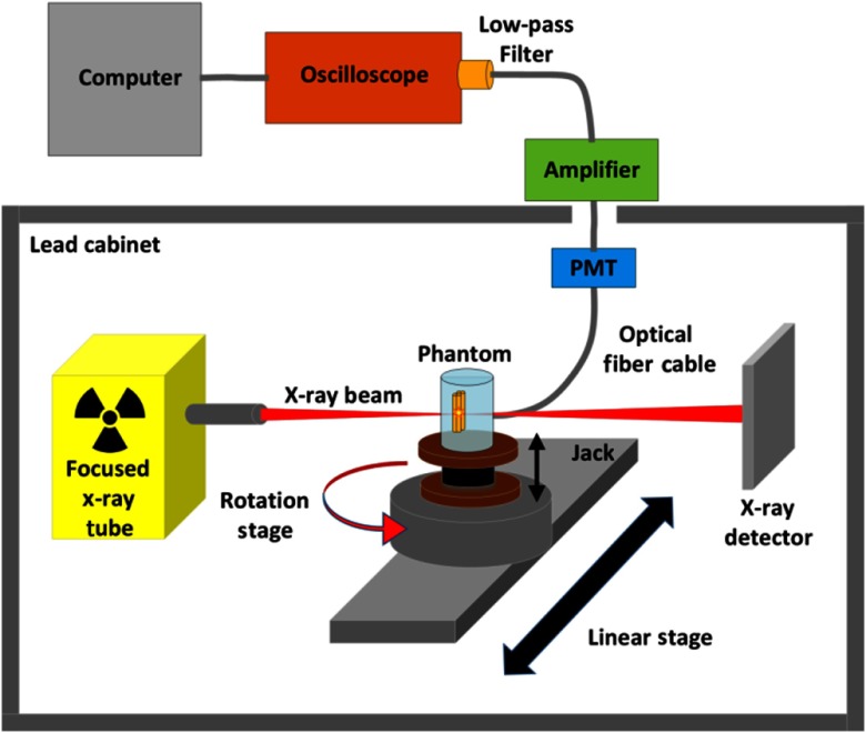
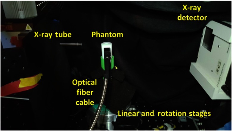
We have performed XLCT imaging of a cylindrical phantom using our focused x-ray beam-based XLCT imaging system, which was previously described in Ref. 10. Figure 1 shows a schematic representation of the XLCT system. In short, we used an x-ray tube (max: 50 kVp and 1.0 mA) with an attached polycapillary lens [X-Beam Powerflux (Mo Anode), XOS] to generate an x-ray beam that was focused to a fine spot of diameter. The object stage where the phantom is placed was at the focal spot of the x-ray beam and was mounted to a manual lab jack (LJ750/M, Thorlabs) which allows us to adjust the scanning depth (defined as the distance from the object top surface to the scanned section). Based on the phantom’s size and location, the x-ray beam diameter varied from to . The jack was mounted on a rotational stage (B4872TS-ZR, Velmex Inc.) and then on a linear stage (Unislide MA40, Velmex Inc.) for rotating and translating the object at different depths. The accuracy of the linear stage is . The transmitted x-ray beam was detected by an x-ray detector (Shad-o-Box 1024, Teledyne Rad-icon Imaging Corp.) mounted opposite of the x-ray tube and was used to monitor the x-ray beam location relative to the phantom geometry. A single optical fiber bundle was mounted using a custom 3D-printed holder and detected the optical photons that reached the object surface close to the fiber bundle and delivered the photons to a fan-cooled photomultiplier tube (PMT) (H7422P-50, Hamamatsu) operated at a control voltage of 0.751 V. The signal from the PMT was then sent to an amplifier (SR445A, Stanford Research Systems) and was amplified 25 times before being filtered with a band low-pass (BLP) filter (BLP-, cut-off frequency: 11 MHz, mini-circuits) to reduce high-frequency noise before finally being collected and displayed by a high-speed oscilloscope (MDO-3014, Tektronix). Finally, the digitized signals acquired by the oscilloscope were saved to a lab computer. The entire system up to the PMT was inside of a light-tight and x-ray shielding lead cabinet with the PMT further shielded from the scattered x-ray photons by a lead sheet. The XLCT imaging system was controlled with custom programs on the lab computer.
Fig. 1.
Schematic representation of the XLCT system used in phantom experiments.
2.2. Scanning Scheme
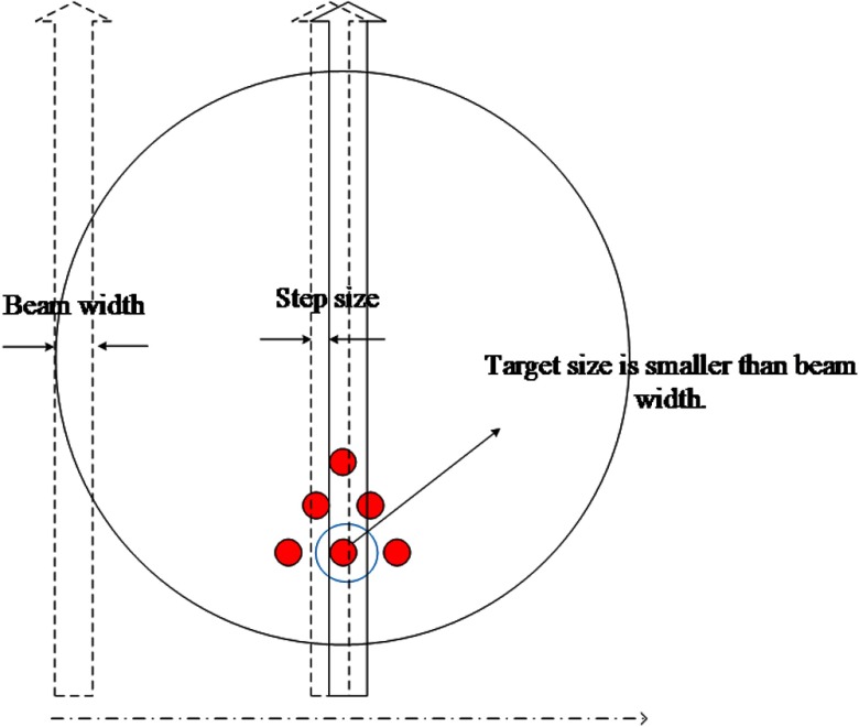
In the scanning scheme of the conventional narrow x-ray beam-based XLCT, the object is scanned by a sequence of single x-ray beams moving at predefined directions and positions, which is similar to the first-generation x-ray computed tomography (CT) scanning mode. It can be extended to the multibeam scanning strategy using multiple pinhole collimators,8 but the scanning step size is still kept equal to the x-ray beam width. Under such kind of scanning strategies, the spatial resolution in narrow beam XLCT is determined by the beam width. In this study, we modified the scanning scheme of the conventional narrow-beam XLCT by reducing the scanning step size to be less than the x-ray beam size. This modification can be performed on both single-beam and multibeam scanning strategies but is only demonstrated here with the single-beam approach for simplicity. Figure 2 shows the single-beam scanning strategy for a typical angular projection. As seen in Fig. 2, the linear scan step size as well as target diameter is set smaller than beam width. For each angular projection, the number of linear scanning steps () is determined by the diameter of entire scanning region () and the scanning step size () as .
Fig. 2.
Schematic representation of linear scan setup for one typical angular projection. The red dots indicate the targets. The vertical arrows indicate the x-ray beams.
2.3. Numerical Simulation Setup
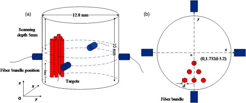
To validate the feasibility and effectiveness of our proposed scanning strategy in XLCT, four cylindrical phantoms (phantoms A, B, C, and D) were designed for numerical simulations. For all phantoms, the diameter and height were set to 12.8 and 10 mm, respectively, as shown in Fig. 3(a). Six luminescent targets of 6 mm in height were placed in the phantoms at a depth of 2 mm. The diameter and EED settings of the six targets for all four numerical phantoms are listed in Table 1. The positions of the six targets and the four fiber bundles are shown in Fig. 3(b). The targets’ diameter is the same as the EED, which has been changed from 0.4 to 0.8 mm in this study. In the transverse plot, as shown in Fig. 3(b), the six targets formed an equilateral triangle whose centroid was fixed at (0, ). The absorption coefficient () and the reduced scattering coefficient () of the phantom were set to 0.0072 and , respectively, at the wavelength of 703 nm, which is the longest wavelength peak in the emission spectrum of . In the simulation studies, we set the phosphor particle concentration to be 1.0 and 0 mg/mL in the target and background regions, respectively.
Fig. 3.
Phantom geometry and detectors setup used in the numerical simulations. (a) Overall phantom geometry and (b) transverse plot of the phantom to show the positions of six targets and four fiber bundles.
Table 1.
The geometry of the targets embedded in phantoms A, B, C, and D.
| Phantom | ||||
|---|---|---|---|---|
| A | B | C | D | |
| Target diameter (mm) | 0.8 | 0.6 | 0.5 | 0.4 |
| EED (mm) | 0.8 | 0.6 | 0.5 | 0.4 |
For all numerical simulations, four optical fiber bundles were placed 2 mm below the scanned section and 90 deg apart from each other, which were employed to collect the emitted photons on the phantom surface, as shown in Fig. 3(a). The diameter of the x-ray beam was fixed at 0.8 mm, and the linear scan step size was set to 0.8, 0.4, 0.2, and 0.1 mm, respectively, for each simulation. We used six angular projections with the angular step size of 30 deg. The numerical measurements at each angular projection were generated with the forward model of XLCT proposed in Refs. 8 and 10. To make the simulations more realistic, 50% white Gaussian noise was added to the numerical measurements.
2.4. Phantom Experimental Setup
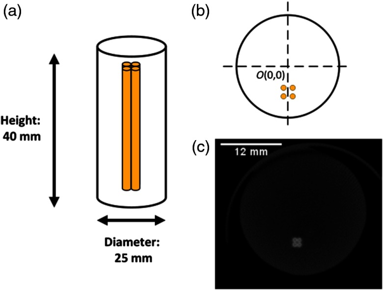
We performed our XLCT scan on a cylindrical phantom (Figs. 4 and 5). A schematic of the phantom is shown in Figs. 4(a) and 4(b) from which we can see that the phantom had a diameter of 25 mm and a height of 40 mm and was composed of 1% intralipid and 2% agar and was embedded off-center with four capillary tube targets. The same background solution was mixed with 10 mg/mL of particles (UKL63/UF-R1, Phosphor Technology Ltd.) and was injected into the capillary tubes (Drummond Scientific) which had an inner diameter and an outer diameter of 0.4 and 0.8 mm, respectively. After the phantom was created and completely solidified, we performed a micro-CT scan using our lab-made micro-CT system, as previously described in Ref. 24, to determine the positions of the embedded targets. A single slice from the micro-CT reconstruction, corresponding to the XLCT scanning section, is shown in Fig. 4(c). Based on the image, the center positions of the four embedded targets were determined to be (, ), (, ), (, ), and (, ) from the center of the phantom. We then performed an XLCT scan of the phantom to validate the proposed method, as seen in Fig. 5. We operated the x-ray tube at 30 kV and 0.5 mA and took measurements at six projections (30 deg/projection) using 520 steps of step size (four times smaller step size than our normal parameters). Lastly, we acquired 10 ms of data from the PMT at each step, similar to Ref. 12.
Fig. 4.
Phantom for experimental studies. (a) Schematic representation of the side view; (b) schematic representation of the top view; and (c) micro-CT image of phantom used in study.
Fig. 5.
Phantom setup inside of XLCT system.
2.5. X-Ray Luminescence Computed Tomography Image Quality Evaluation Criteria
To analyze the reconstructed XLCT images quantitatively, four criteria were used to evaluate the quality of the reconstructed XLCT images.
Dice similarity coefficient (DICE) is used for quantifying the shape and location accuracy between the reconstructed and the true target regions,25 which is obtained as follows:
| (1) |
where is the reconstructed region of interest that is defined to be the pixels whose intensities are higher than 10% of the maximum of the normalized reconstructed intensity, and is the true target location. Generally, the closer the DICE is to 100%, the better is the reconstruction accuracy.
Target size error (TSE). This criterion is defined as the target diameter error ratio between the reconstructed target and the true target:8
| (2) |
where and are the diameters of reconstructed and true targets, respectively. Here, is calculated from the cross-target profile plot by using the full width at tenth maximum approach, in which we measured the width at the tenth of the maximum.
Spatial resolution index (SPI). SPI is used to evaluate the performance of our proposed scanning strategy in resolving two targets26 and is calculated as
| (3) |
where denotes the value of the profile along a given line on the reconstructed cross section. Here, , , and are the maximal, minimal, and valley values between the two peak values, respectively. The closer the SPI is to 1, the better it is in resolving adjacent targets.
Normalized mean square error (NMSE). NMSE is applied to evaluate the relative error between the reconstructed and the true targets,27 which is defined as
| (4) |
where and are the reconstructed and actual nanophosphor distributions, respectively.
3. Results
3.1. Numerical Simulations
XLCT image reconstruction was performed using the regularization method with the majorization–minimization (MM) reconstruction framework, which was developed in Ref. 16, but was adapted to solve the inverse problem in XLCT imaging, following the steps as described in Refs. 23, 25, and 28. For the XLCT simulations, the phantom was discretized by a finite-element mesh (FEM) with 26,638 nodes, 153,053 tetrahedral elements, and 11,456 face elements, and the reconstructed section was interpolated onto a grid of size and then the system matrix was interpolated onto the grid from the FEM.
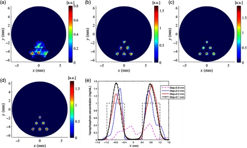
For the simulations of phantom A, we simulated XLCT scanning using a straight x-ray beam with a fixed diameter of 0.8 mm but with different scanning step sizes from 0.8, 0.4, 0.2 to 0.1 mm. Figure 6 plots the reconstructed XLCT images of phantom A with different scanning step sizes of 0.8 mm [Fig. 6(a)], 0.4 mm [Fig. 6(b)], 0.2 mm [Fig. 6(c)], and 0.1 mm [Fig. 6(d)]. From Fig. 6, we can see substantial improvements in the image quality by decreasing the scanning step size. Figure 6(e) shows the intensity profiles along the center line of the middle row targets in Figs. 6(a)–6(d). The quantitative analysis results of the simulations using phantom A are presented in Table 2. As shown in Table 2, when the scanning step size reduces from 0.8 to 0.1 mm, each of the calculated image quality metrics improved quite substantially. This indicates the improvements in shape and location accuracy, target size accuracy, spatial resolution, and overall reconstruction accuracy. There is a further increment of DICE and decrement of TSE and NMSE as the scanning step size decreases from 0.4 to 0.2 mm. There are no significant changes in DICE, TSE, SPI, and NMSE when the scanning step size is reduced from 0.2 [Fig. 6(c)] to 0.1 mm [Fig. 6(d)].
Fig. 6.
Reconstructed XLCT images for the simulations of phantom A with different scanning step sizes: (a) 0.8 mm, (b) 0.4 mm, (c) 0.2 mm, and (d) 0.1 mm. (e) Intensity profiles along the center line of the middle row targets of phantom A.
Table 2.
The quantitative metrics for the simulations of phantom A with different scanning step sizes.
| Scan step (mm) | DICE (%) | TSE (%) | SPI | NMSE |
|---|---|---|---|---|
| 0.8 | 39.7 | 38.8 | 0.693 | 0.602 |
| 0.4 | 83.6 | 10.9 | 0.994 | 0.191 |
| 0.2 | 90.7 | 5.0 | 0.995 | 0.139 |
| 0.1 | 90.6 | 6.3 | 0.992 | 0.132 |
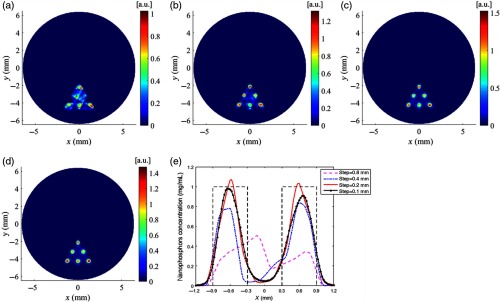
For the simulations of phantom B, we simulated XLCT scanning with the same scan settings as the previous simulation. Figure 7 shows the reconstruction images of phantom B. The six targets were hardly resolved when the scanning step size of 0.8 mm was adopted, as shown in Fig. 7(a). When the scanning step size of 0.4 mm, which is smaller than the target diameter, was used, the six targets were easily resolved with better shapes at the correct locations, as shown in Fig. 7(b). The quality of the reconstructed images was improved further by decreasing the scanning step size to 0.2 and 0.1 mm, as shown in Figs. 7(c) and 7(d). Figure 7(e) plots the intensity profiles along the center line of the middle row targets in Figs. 7(a)–7(d). The quantitative analysis results are listed in Table 3, from which we see the improvement of the reconstruction quality such as the shape and location accuracy, target size accuracy, spatial resolution, and reconstruction accuracy when the scanning beam size was reduced. We have also noticed that there are only slight differences in the quantitative analysis results of DICE, SPI, and NMSE when the scanning step size is reduced from 0.2 to 0.1 mm.
Fig. 7.
Reconstructed XLCT images for the simulations of phantom B with different scanning step sizes: (a) 0.8 mm, (b) 0.4 mm, (c) 0.2 mm, and (d) 0.1 mm. (e) Intensity profiles along the center line of the middle row targets of phantom B.
Table 3.
The quantitative metrics for the simulations of phantom B with different scanning step sizes.
| Scan step (mm) | DICE (%) | TSE (%) | SPI | NMSE |
|---|---|---|---|---|
| 0.8 | 55.9 | 33.0 | 0.649 | 0.485 |
| 0.4 | 70.3 | 22.9 | 0.954 | 0.226 |
| 0.2 | 81.7 | 17.7 | 0.970 | 0.159 |
| 0.1 | 80.9 | 12.9 | 0.952 | 0.164 |
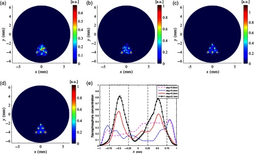
We conducted numerical simulations on phantom C with the same scan settings as the previous simulations. The reconstructed images of phantom C are plotted in Fig. 8, from which we can see that all targets could be resolved successfully for the step sizes of 0.2 and 0.1 mm. Intensity profiles along the center line of the middle row targets in Figs. 8(a)–8(d) were drawn and displayed in Fig. 8(e). The DICE, TSE, SPI, and NMSE of the reconstruction results were calculated and are listed in Table 4. As the scanning step size reduced from 0.8 to 0.1 mm, the SPI increased monotonically from 0.836 to 0.924, indicating that the proposed scanning strategy with a smaller scanning step size achieved much better separation of the targets. At the same time, a monotonic improvement of the reconstruction accuracy can be maintained as indicated by the NMSE shown in Table 4. The reduction of scanning step size can result in better accuracy of the reconstructed shape and location of targets as indicated by DICE and TSE.
Fig. 8.
Reconstructed XLCT images for the simulations of phantom C with different scanning step sizes: (a) 0.8 mm, (b) 0.4 mm, (c) 0.2 mm, and (d) 0.1 mm. (e) Intensity profiles along the center line of the middle row targets of phantom C.
Table 4.
The quantitative metrics for the simulations of phantom C with different scanning step sizes.
| Scan step (mm) | DICE (%) | TSE (%) | SPI | NMSE |
|---|---|---|---|---|
| 0.8 | 38.8 | 59.2 | 0.836 | 0.767 |
| 0.4 | 47.0 | 45.4 | 0.872 | 0.601 |
| 0.2 | 58.5 | 43.3 | 0.904 | 0.437 |
| 0.1 | 53.7 | 36.2 | 0.924 | 0.332 |
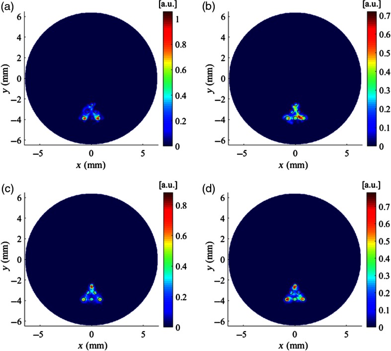
To further study the performance limitation of the proposed scanning strategy in resolving targets with a diameter smaller than the x-ray beam width, we simulated XLCT imaging of phantom D, in which both the target diameter and the EED were set to be 0.4 mm, half of the beam diameter. Figure 9 shows the reconstructed XLCT images for this case. From Fig. 9, we can see that image quality has improved slightly when the step size decreased. However, the reconstructed XLCT image could not resolve all the six targets even if the step size is reduced to 0.1 mm, which means that the spatial resolution of XLCT imaging depends not only on the scanning step size but also on the x-ray beam size.
Fig. 9.
Reconstructed XLCT images for the simulations of phantom D with different scanning step sizes: (a) 0.8 mm, (b) 0.4 mm, (c) 0.2 mm, and (d) 0.1 mm.
3.2. Phantom Experiment
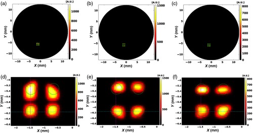
XLCT image reconstruction was performed from the measurements using a similar approach as the numerical simulations. The regularized MM algorithm was again utilized with the same FEM, interpolated onto a grid. From the XLCT measurement data, we reconstructed three different cases, differing by their linear scanning step sizes: (no reduction in step size), (two times reduction in step size), and (four times reduction in step size) and plotted the results and their corresponding line profile plots for the respective cases in Figs. 10 and 11. The profile positions used are shown in Figs. 10(d)–10(f) where the blue line shows the horizontal position and the magenta line indicates the vertical line profile position. We also performed quantitative analyses by calculating the DICE, TSE, and SPI, as shown in Table 5. The true target locations (ground truth) were determined from the micro-CT image [Fig. 4(c)] and are shown by the green circles in the reconstructed XLCT images. Overall we can see that as the step size decreased, there was an overall improvement in the image quality and the ability to resolve the targets. In addition, the DICE increased from 50.7 to 53.2 and finally to 67.2%; the TSE decreased from 12.5 to 10.9, and finally to 7.8%; and the SPI has an obvious improvement from 0.762 to 0.906, and finally to 0.922, as the step size decreased from 200 to and finally to (Table 5). Overall our XLCT image reconstruction successfully validates the improvement from our proposed scanning strategy.
Fig. 10.
Reconstructed XLCT images and the zoomed-in target regions from the phantom experiment for the different cases. (a) No step size reduction. (b) step size reduction. (c) step size reduction. (d) Zoomed-in target region from (a). (e) Zoomed-in target region from (b). (f) Zoomed-in target region from (c). The green circles represent the true target positions obtained from the micro-CT scan.
Fig. 11.
Intensity profile plots corresponding to the line positions shown in Figs. 10(d)–10(f). (a) Horizontal line profile across bottom two targets. (b) Vertical line profile across left two targets. The intensities are normalized individually to their own line intensities.
Table 5.
The image quality metrics of XLCT-reconstructed images for the phantom experiment.
| Case | DICE (%) (bottom targets) | TSE (%) | SPI |
|---|---|---|---|
| No step reduction (step size of 200 ) | 50.7 | 12.5 | 0.762 |
| step size reduction (step size of ) | 53.2 | 10.9 | 0.906 |
| step size reduction (step size of ) | 67.2 | 7.8 | 0.922 |
4. Discussions and Conclusion
State-of-the-art high-resolution imaging techniques are a driving force behind current biomedical science. Among such, microscopic XLCT imaging stands out as it has the potential to obtain both high sensitivity and spatial resolution. However, its high spatial resolution capacity has not been fully implemented yet. According to previous studies, the spatial resolution limit of XLCT is generally believed to be determined by the beam aperture size. Therefore, generation of superfine x-ray beams, such as superfine collimated x-ray beams imaging11 and focused x-ray beams imaging,12 is generally thought to be the only way to improve the spatial resolution of XLCT imaging. However, both methods for generating superfine beams have their own shortcomings. In this paper, a scanning strategy, in which the scanning step size is reduced to be less than the x-ray beam size, is proposed to break the spatial resolution limit of the traditional narrow x-ray beam-based XLCT system.
The numerical simulations have demonstrated that the proposed scanning strategy of a smaller step size can achieve better results in the DICE, TSE, and SPI than the traditional one where the step size was equal to the x-ray beam diameter. We have found that targets can be resolved successfully with the proposed scanning strategy when the target size and the EED between targets are smaller than the beam width. We have also conducted XLCT simulations using phantoms with a smaller EED. The first phantom was similar to phantom B except the different EED which was changed from 0.7 to 0.2 mm with an interval of 0.1 mm. The second phantom was similar to phantom C except the different EED which was changed from 0.6 to 0.3 mm with an interval of 0.1 mm. In these numerical studies, the diameter of x-ray beams and the linear scan step size were fixed as 0.8 and 0.1 mm, respectively. With the smaller EED, it is more challenging to reconstruct all targets. However, the proposed scanning strategy has reconstructed all the targets successfully for these cases, while the previously reported scanning method with the same beam size and scanning step size could not resolve all the targets for these cases with much smaller EED than the beam size. These reconstructed XLCT images and detailed analysis are not included in this paper for simplicity. These findings help to extend the theory that the spatial resolution of XLCT imaging is determined by not only the x-ray beam size but also the scanning step size. The numerical simulations have demonstrated that our proposed method was also stable and robust against noises. The results of the phantom experiment have also further validated that the proposed scanning strategy can achieve better results in XLCT image reconstruction.
Furthermore, we have performed the numerical simulations of XLCT imaging with the same x-ray beam parameters as those in the experimental XLCT imaging. These numerical simulations have further validated the proposed method of improving the spatial resolution of XLCT imaging by reducing the scanning step size.
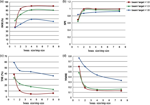
Certainly, there is an upper bound of spatial resolution improvement by reducing the scanning step size. As shown in the numerical simulation study of phantom D, XLCT could not resolve all the six targets when the scanning step size was reduced to 0.1 mm, because the x-ray beam diameter was 0.8 mm, which was larger than the target diameter of 0.4 mm. From this study, we know that the spatial resolution of XLCT imaging depends both on the x-ray beam size and the scanning step size. To further investigate the relationship between the XLCT-reconstructed image quality and our proposed method, we have plotted the relative dependence of the four image quality metrics as a function of the x-ray beam size and the scanning step size for different ratios of the x-ray beam size to target diameter (beam/target) in Fig. 12, for the successful numerical simulation cases (phantoms A to C). For each setting of the beam/target ratio, we can see that the reconstructed XLCT image quality has a significant improvement as the ratio of the beam size to step size increased from 1 to 4 with increments in both DICE and SPI and decrements in TSE and NMSE. When the beam size/step size ratio is increased to 8, there are no significant changes in the XLCT image quality. Based on Fig. 12, our results currently demonstrate that the ideal step size in consideration of the image enhancement and measurement time should be ¼ of the x-ray beam size. Also, when the beam size/step size is larger than 2, the reconstructed image quality increases as the ratio of beam size to target diameter decreases. Therefore, the ideal beam size should be as small as possible according to the trade-off of the spatial resolution and the measurement time.
Fig. 12.
The relative dependence of four XLCT image quality evaluation criteria (DICE, SPI, TSE, and NMSE) as a function of beam size/step size in terms of different cases of beam size/target diameter. (a) DICE, (b) SPI, (c) TSE, and (d) NMSE.
We have shown that XLCT imaging with reduced scanning step size can reach a better spatial resolution. However, the reduced step size-based scanning strategy needs more scan steps to cover the same field of view as before, which means more measurement time is required with the current configuration. To overcome this problem of long scanning time, we used a highly sensitive PMT and a focused x-ray beam with high x-ray intensity to reduce the measurement time per scan step. The current measurement time with the step size of was or 31.2 s, if neglecting the stage movement time. The measurement time can be further reduced to make it more suitable for practical use. One possible way is incorporation of the preacquired permissible region of the targets into the scanning configuration to reduce the scanning area and improve the scanning efficiency. The permissible region strategy has been adopted in a cone beam-based XLCT imaging.14
It is worth noting that we have used four detector fibers in our numerical simulations studies and only one detector fiber in our experimental imaging system. Both studies with either one detector fiber or four detector fibers have verified the efficacy of the proposed method. Currently, we only have one PMT measurement unit in our lab. We are building the next generation of XLCT imaging system, in which we plan to use four fiber bundles with four PMT detection units.29
In previous work, we have performed a sensitivity study of XLCT24 under the traditional scanning strategy. In this study, we do not expect the sensitivity to be reduced because other imaging parameters were kept the same as before, except the reduced scanning step size. The sensitivity of the proposed approach should be studied further in the future.
In sum, we have performed four sets of numerical simulations and one set of phantom experiments to validate the proposed scanning scheme of narrow beam-based XLCT imaging. Our results have demonstrated that the scanning scheme can improve the spatial resolution substantially, compared to previous methods. In particular, the improvement is up to two times from 0.8 to 0.4 mm for the case with an x-ray beam diameter of 0.8 mm.
Acknowledgments
The authors acknowledge funding support from the National Natural Science Foundation of China (No. 81571723) and the U.S. National Institutes of Health (NIH) (No. R01 EB026646). The authors also acknowledge Dr. Simon R. Cherry from UC Davis for lending us the micro-CT system used in this study.
Biographies
Yueming Zhang received her BS degree in electronic information engineering from Tianjin Polytechnic University, in 2017. She is pursuing her MS degree in biomedical engineering at Tianjin University. Her research interests include instrumentation and algorithm development for x-ray luminescence computed tomography (XLCT) imaging.
Michael C. Lun is currently a PhD candidate at the University of California, Merced, in the bioengineering graduate program working with Dr. Changqing Li. His research interest is in the area of biomedical optical imaging, from hardware design to image reconstruction. His current research project focuses on the development of a small-animal-dedicated XLCT imaging system.
Changqing Li is an associate professor in the Department of Bioengineering, University of California, Merced. He received his PhD from the Department of Biomedical Engineering, University of Florida, in 2006. His research topics include biomedical optical imaging, x-ray imaging, and their applications in cancer imaging and drug delivery monitoring.
Zhongxing Zhou received his bachelor’s, master’s, and PhD degrees in biomedical engineering from the School of Precision Instruments and Optoelectronics Engineering, Tianjin University, in 2003, 2006, and 2009, respectively. Since 2012, he has been with Tianjin University as an associate professor in biomedical engineering. His research interests include advanced x-ray imaging techniques, medical imaging, and biomedical signal processing.
Disclosures
The authors declare that there are no conflicts of interest related to this article.
References
- 1.Carpenter C. M., et al. , “Hybrid x-ray/optical luminescence imaging: characterization of experimental conditions,” Med. Phys. 37, 4011–4018 (2010). 10.1118/1.3457332 [DOI] [PMC free article] [PubMed] [Google Scholar]
- 2.Pratx G., et al. , “Tomographic molecular imaging of x-ray-excitable nanoparticles,” Opt. Lett. 35, 3345–3347 (2010). 10.1364/OL.35.003345 [DOI] [PubMed] [Google Scholar]
- 3.Pratx G., et al. , “X-ray luminescence computed tomography via selective excitation: a feasibility study,” IEEE Trans. Med. Imaging 29, 1992–1999 (2010). 10.1109/TMI.2010.2055883 [DOI] [PubMed] [Google Scholar]
- 4.Li C., et al. , “Three-dimensional fluorescence optical tomography in small-animal imaging using simultaneous positron-emission-tomography priors,” Opt. Lett. 34(19), 2933–2935 (2009). 10.1364/OL.34.002933 [DOI] [PMC free article] [PubMed] [Google Scholar]
- 5.Cong W., Wang C., Wang G., “Stored luminescence computed tomography,” Appl. Opt. 53, 5672–5676 (2014). 10.1364/AO.53.005672 [DOI] [PubMed] [Google Scholar]
- 6.Zhang W., et al. , “Microscopic x-ray luminescence computed tomography,” Proc. SPIE 9316, 93160M (2015). 10.1117/12.2076797 [DOI] [Google Scholar]
- 7.Tzoumas S., Vernekohl D., Xing L., “Coded-aperture compressed sensing x-ray luminescence tomography,” IEEE Trans. Biomed. Eng. 65, 1892–1895 (2016). 10.1109/TBME.2017.2770148 [DOI] [PubMed] [Google Scholar]
- 8.Zhang W., et al. , “Multiple pinhole collimator based x-ray luminescence computed tomography,” Biomed. Opt. Express 7, 2506–2523 (2016). 10.1364/BOE.7.002506 [DOI] [PMC free article] [PubMed] [Google Scholar]
- 9.Zhang G., et al. , “Cone beam x-ray luminescence computed tomography based on Bayesian method,” IEEE Trans. Med. Imaging 36, 225–235 (2017). 10.1109/TMI.2016.2603843 [DOI] [PMC free article] [PubMed] [Google Scholar]
- 10.Zhang W., et al. , “X-ray luminescence computed tomography using a focused x-ray beam,” J. Biomed. Opt. 22, 116004 (2017). 10.1117/1.JBO.22.11.116004 [DOI] [PMC free article] [PubMed] [Google Scholar]
- 11.Zhang W., et al. , “Collimated superfine x-ray beam based x-ray luminescence computed tomography,” J. X-Ray Sci. Technol. 25, 945–957 (2017). 10.3233/XST-17265 [DOI] [PMC free article] [PubMed] [Google Scholar]
- 12.Lun M. C., Zhang W., Li C., “Focused x-ray luminescence computed tomography: experimental studies,” Proc. SPIE 10871, 108710G (2019). 10.1117/12.2506927 [DOI] [PMC free article] [PubMed] [Google Scholar]
- 13.Cong W., Shen H., Wang G., “Spectrally resolving and scattering-compensated x-ray luminescence/fluorescence computed tomography,” J. Biomed. Opt. 16, 066014 (2011). 10.1117/1.3592499 [DOI] [PMC free article] [PubMed] [Google Scholar]
- 14.Yi H., et al. , “A permissible region extraction based on a knowledge priori for x-ray luminescence computed tomography,” Multimedia Syst. 25(2), 147–154 (2017). 10.1007/s00530-017-0576-3 [DOI] [Google Scholar]
- 15.Zhang G., et al. , “Generalized adaptive Gaussian Markov random field for x-ray luminescence computed tomography,” IEEE Trans. Biomed. Eng. 65, 2130–2133 (2018). 10.1109/TBME.10 [DOI] [PubMed] [Google Scholar]
- 16.Tian Y., et al. , “Preparation and luminescence property of Gd2O2S:Tb x-ray nano-phosphors using the complex precipitation method,” J. Alloy. Compounds 433, 313–317 (2007). 10.1016/j.jallcom.2006.06.075 [DOI] [Google Scholar]
- 17.Osakada Y., et al. , “X-ray excitable luminescent polymer dots doped with an iridium(III) complex,” Chem. Commun. 49, 4319–4321 (2013). 10.1039/c2cc37169c [DOI] [PubMed] [Google Scholar]
- 18.Sudheendra L., et al. , “NaGdF4:Eu3+ nanoparticles for enhanced x-ray excited optical imaging,” Chem. Mater. 26, 1881–1888 (2014). 10.1021/cm404044n [DOI] [PMC free article] [PubMed] [Google Scholar]
- 19.Zhang W., et al. , “Sub-10 nm water-dispersible beta-NaGdF4:X% Eu3+ nanoparticles with enhanced biocompatibility for in vivo x-ray luminescence computed tomography,” ACS Appl. Mater. Interfaces 9, 39985–39993 (2017). 10.1021/acsami.7b11295 [DOI] [PubMed] [Google Scholar]
- 20.Guo T., et al. , “High-efficiency x-ray luminescence in Eu3+-activated tungstate nanoprobes for optical imaging through energy transfer sensitization,” NanoScale 10, 1607–1612 (2018). 10.1039/C7NR06405E [DOI] [PubMed] [Google Scholar]
- 21.Chen D., et al. , “Cone beam x-ray luminescence computed tomography: a feasibility study,” Med. Phys. 40, 031111 (2013). 10.1118/1.4790694 [DOI] [PubMed] [Google Scholar]
- 22.Chen D., et al. , “Quantitative cone beam x-ray luminescence tomography/x-ray computed tomography imaging,” Appl. Phys. Lett. 105, 191104 (2014). 10.1063/1.4901436 [DOI] [Google Scholar]
- 23.Li C., Martinez-Davalos A., Cherry S. R., “Numerical simulation of x-ray luminescence optical tomography for small-animal imaging,” J. Biomed. Opt. 19, 046002 (2014). 10.1117/1.JBO.19.4.046002 [DOI] [PMC free article] [PubMed] [Google Scholar]
- 24.Lun M. C., Zhang W., Li C., “Sensitivity study of x-ray luminescence computed tomography,” Appl. Opt. 56, 3010–3019 (2017). 10.1364/AO.56.003010 [DOI] [PMC free article] [PubMed] [Google Scholar]
- 25.Zhu D., Li C., “Nonconvex regularizations in fluorescence molecular tomography for sparsity enhancement,” Phys. Med. Biol. 59, 2901–2912 (2014). 10.1088/0031-9155/59/12/2901 [DOI] [PubMed] [Google Scholar]
- 26.Gao P., et al. , “Sparse view cone beam x-ray luminescence tomography based on truncated singular value decomposition,” Opt. Express 26, 23233–23250 (2018). 10.1364/OE.26.023233 [DOI] [PubMed] [Google Scholar]
- 27.Chen D., et al. , “X-ray luminescence computed tomography imaging based on x-ray distribution model and adaptively split Bregman method,” Biomed. Opt. Express 6, 2649–2463 (2015). 10.1364/BOE.6.002649 [DOI] [PMC free article] [PubMed] [Google Scholar]
- 28.Zhu D., Li C., “Nonuniform update for sparse target recovery in fluorescence molecular tomography accelerated by ordered subsets,” Biomed. Opt. Express 5, 4249–4259 (2014). 10.1364/BOE.5.004249 [DOI] [PMC free article] [PubMed] [Google Scholar]
- 29.Lun M. C., et al. , “Development of a focused-x-ray luminescence tomography (FXLT) system,” arXiv:1709.10186 (2017).


