Abstract
Objective This study aims to evaluate, through biomechanical tests, the resistance and energy required for proximal femoral fracture in synthetic bones after removing cannulated screws shaped as an inverted triangle, comparing the obtained results to those of a reinforcement technique with polymethylmethacrylate (PMMA) as bone cement.
Methods Twenty synthetic bones were used: 10 units for the control group (CG), 5 units for the test group without reinforcement (TGW/O), and 5 units for the test group using a reinforcement technique with PMMA (TGW). The biomechanical analysis simulated a fall on the large trochanter using a servo-hydraulic machine.
Results All TGW/O and CG specimens had a basicervical fracture. Three TGW specimens presented a basicervical fracture, and two suffered a fracture near the fixation point of the device (femoral diaphyseal region), with one of them being associated with a femoral neck fracture. A mean PMMA volume of 8.2 mL was used to fill the 3 screw holes in the TGW group. According to the one-way analysis of variance (ANOVA) and the Tukey multiple comparisons tests at a 5% level, the TGW presented a statistically significant difference when compared with the other groups in all parameters: maximal load ( p = 0.001) and energy until fracture ( p = 0.0001).
Conclusion The simple removal of the cannulated screws did not reduce significantly the maximum load and energy for fracture occurrence, but the proximal femoral reinforcement with PMMA significantly increased these parameters, modifying the fracture pattern.
Keywords: hip fractures, femoral fractures, osteoporosis, polymethylmethacrylate
Introduction
Osteoporosis is a public health problem for the world population, and it is more prevalent in elderly women. It is characterized by bone mineral density reduction, which decreases the mechanical resistance of this tissue. Its main socioeconomic impact factor is the occurrence of fractures by low-energy trauma, including proximal femoral fracture (PFF), which has the highest morbidity and mortality rate. 1 2
The surgical treatment of these fractures allows resuming of usual activities as quickly as possible through fixation with proximal femoral rods (HFP), cannulated screws (CSs) and/or sliding tube plate (dynamic hip screw, DHS), and joint replacement by hip arthroplasty to reduce the possibility of clinical complications due to patient immobility; all these therapeutic methods are already widely used. 3
The indications for removing the implants used for periprosthetic femoral fracture (PFF) treatment are persistent pain in the gluteal and thigh regions; such pain may be caused by the prominence of the synthetic material, which is common with CSs use due to their usual migration, 4 implant failure or infection. After consolidation of the proximal femoral fracture, implant removal may cause complications, such as possible femoral neck or intertrochanteric fractures, especially in patients with poor bone quality. 2 5 6
Therefore, to describe the results of a static bending test, simulating a fall over the trochanter from synthetic femurs after removing the three CSs shaped as an inverted triangle, in the presence or absence of a reinforcement technique, can lead to the development of clinical trials to determine a more careful indication for synthesis removal.
Material and Methods
This study aimed to evaluate the strength and energy required for proximal femoral fracture in synthetic bone after removing cannulated screws shaped as an inverted triangle comparing results obtained with a reinforcement technique using PMMA. Twenty specimens, model c1010 (Nacional ossos, Jaú, SP, Brazil), made of sponge and cortical polyurethane with 10 pounds per cubic foot (PCF), and a 12-mm medullary canal of the same lot were divided into three groups, including a control group (CG) with 10 femurs, a test group with no reinforcement (TGW/O) with five femurs, and a test group with reinforcement test (TGW) with 5 femurs.
The CG was composed of synthetic femurs with their intact external and internal integrity. On the other hand, in the synthetic femurs from the TGW/O and the TGW, with no previous fractures, three guidewires, shaped as inverted triangles, were introduced equidistant from each other; the inferior one was inserted at the same level of the small trochanter with radioscopic aid in all specimens. Such wires were introduced up to a 5-mm distance from the surface of the femoral head. The wires were measured with the national manufacturer's standard meter (Ortosintese Indústria e Comércio Ltda., São Paulo, SP, Brasil), whereas the length of the screws was determined separately. Holes were made with a cannulated drill from the same manufacturer for the use of 7.5-mm cannulated screws, whose length was previously determined at the initial measurement.
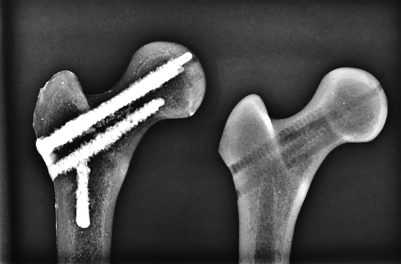
In the TGW/O, the biomechanical test was performed shortly after implant removal, with no reinforcement technique. In the TGW group, after implant removal, the synthetic models were submitted to a reinforcement technique with a PMMA-type bone cement provided by Biomechanical (Biomecânica Indústria e Comércio de produtos Ortopédicos, Jaú, SP, Brasil); the cement had normal viscosity, and it filled the path of the cannulated screws after the anterograde introduction of PMMA with a 20 mL syringe (PMMA volume was recorded) ( Fig. 1 ). Since the femoral canal was inadvertently filled in some specimens, but not the femoral head, an inclusion condition was determined: the entire length of the femoral neck must be filled with PMMA (whereas one of the paths at the femoral head may remain unfilled) and the inadvertent spinal cord filling of less than 5 cm ( Fig. 1 ). All samples were submitted to static bending tests using a servo-hydraulic machine, model MTS 810 - FlexTest 40, with 100 kN capacity (MTS Landmark Testing Solutions, Eden Prairie, MN, EUA).
Fig. 1.
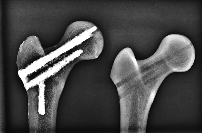
Femurs radiographed after polymethylmethacrylate filling (left) and with no reinforcement (right).
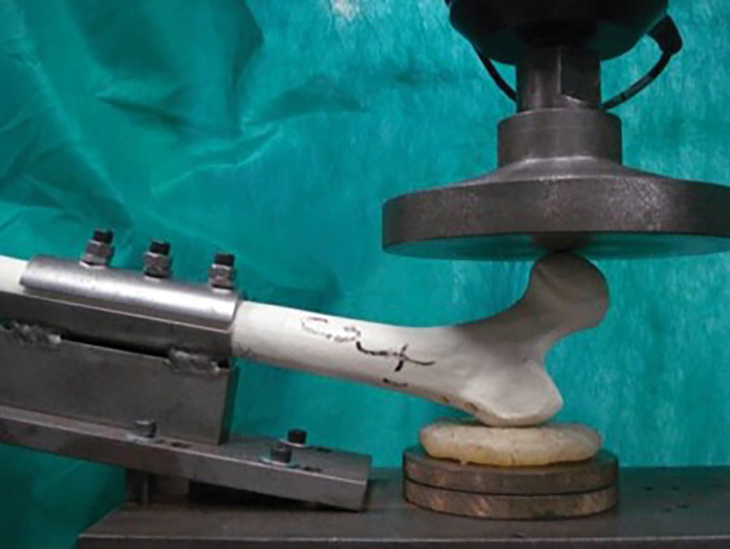
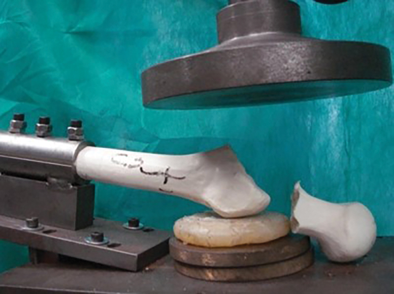
The femur was fixed to the test device leaving 150 mm of its length outside the fastening portion, toward the hydraulic piston placed at the base of the test machine at a 10° angle horizontally and 15° of internal rotation measured with a digital goniometer and with the large trochanter supported on a silicone disc of 8 × 2 cm in diameter ( Fig. 2 ) A 40 N preload, using a 2 mm/s piston displacement rate, was applied at the femoral head until fracture ( Fig. 3 ); the following values were obtained: maximum load and flow load in Newtons (N); energy until flow and energy until fracture in Joules (J); and stiffness in Newtons per millimeter (N/mm).
Fig. 2.
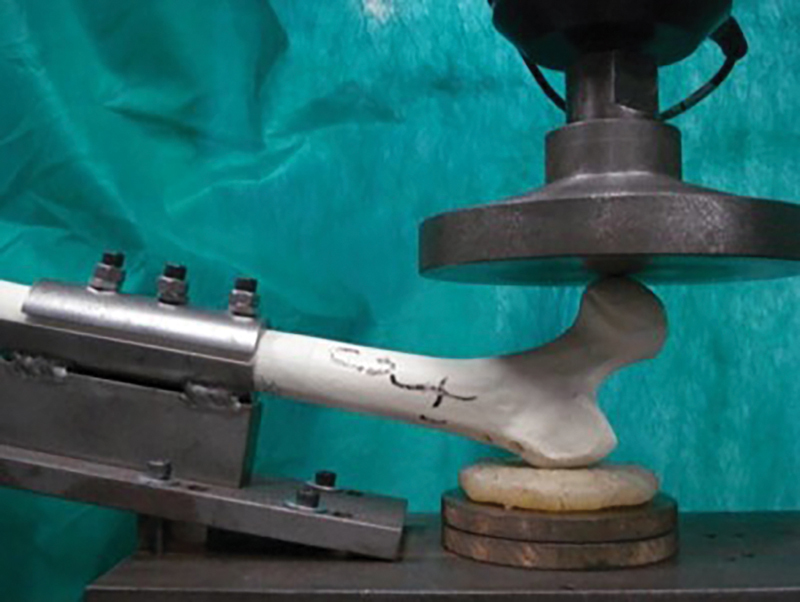
Synthetic bone before the mechanical test.
Fig. 3.
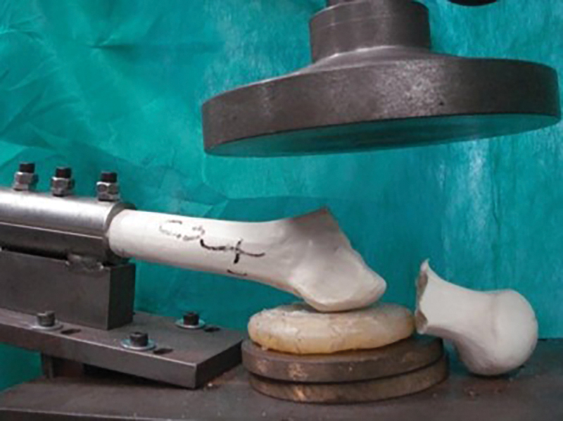
Synthetic bone after the mechanical test. A basicervical fracture is noted in this specimen.
The results were obtained by an inferential analysis consisting of one-way analysis of variance (ANOVA) and multiple comparisons by the Tukey method in order to check whether there is a significant difference in the maximum load and energy until fracture between the groups. Statistical significance was determined at a 5% level. Statistical analysis was performed using the statistical software SPSS, version 20.0 (IBM Corp., Armonk, NY, USA).
Results
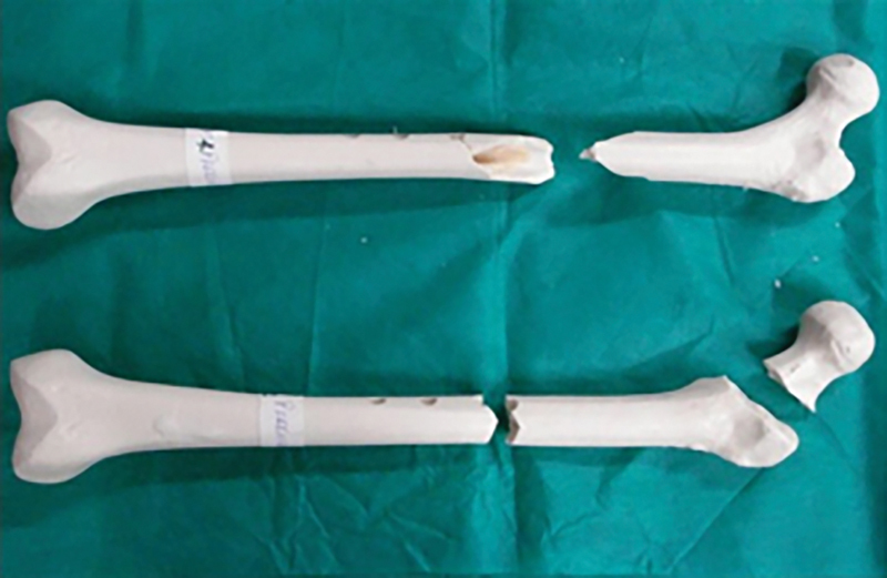
All TGW/O and CG specimens had a basicervical fracture at the femoral neck. In the TGW, three specimens presented a basicervical fracture at the femoral neck, while two had a fracture near the fixation point in the femoral diaphyseal region, one of which associated with a femoral neck fracture ( Fig. 4 ).
Fig. 4.
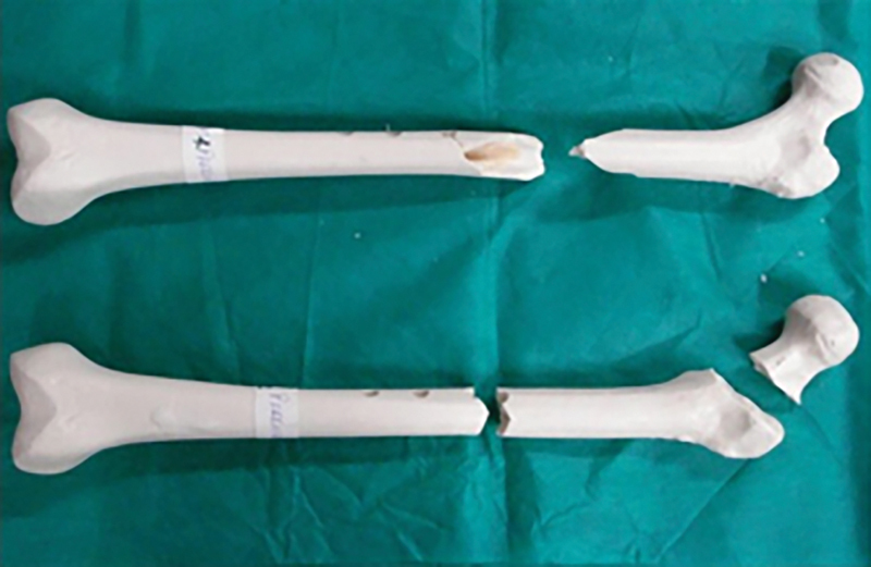
Synthetic specimens with the neck and diaphysis fracture (above) and diaphysis fracture (below) after the mechanical test.
The average PMMA volume used to fill the three cannulated screws holes in each specimen from the TGW group was 8.2 mL.
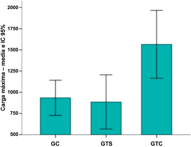
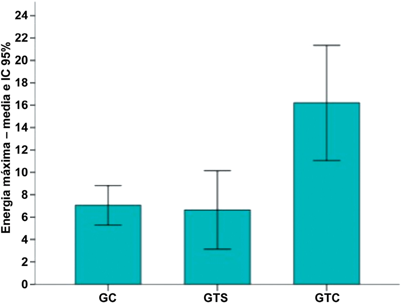
The parameters analyzed in the CG, TGW/O and TGW presented the following averages, respectively: flow load in N (697; 665; 999), energy until flow in J (2.8; 2.4; 3.8), stiffness in N/mm (90, 93, 130), maximum load in N (935, 886, 1,565), and energy until fracture in J (7.1, 6.6, 16.2) ( Figs. 5 and 6 ).
Fig. 5.
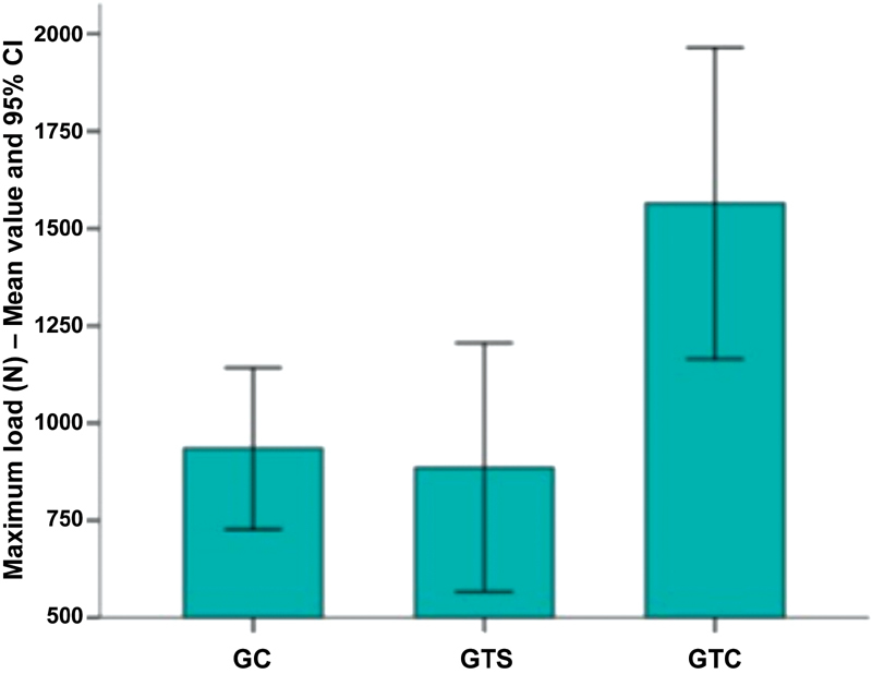
Mean maximum load and 95% confidence interval (CI).
Fig. 6.
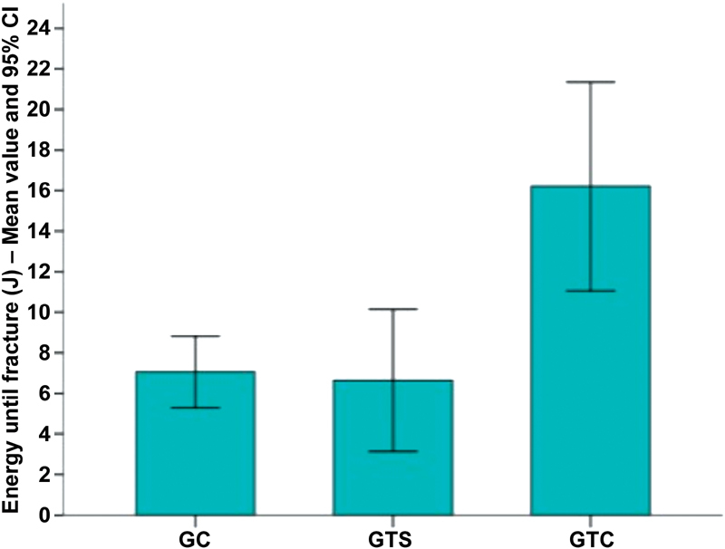
Mean energy until fracture and 95% confidence interval (CI).
Tables 1 and 2 describe the flow/stiffness parameters and maximum load/energy until fracture, respectively, according to the group (CG, TGW/O and TGW) and the corresponding descriptive level ( p- value) derived from one-way ANOVA. The Tukey multiple comparisons test was applied to identify which groups differed significantly at a 5% level ( significant differences column at the table).
Table 1. Comparison of flow load, energy until flow, energy until fracture and stiffness per statistical analyses; 95% confidence interval, 95% confidence interval for the mean value.
| Variable | n | Mean value | 95% CI for the mean value | Minimum value | Maximum value | p -value a | Significant difference b |
|---|---|---|---|---|---|---|---|
| Flow load (N) | |||||||
| CG | 10 | 697 | 559–835 | 316 | 1,010 | Control ≠ PMMA | |
| TGW/O | 5 | 665 | 480–851 | 376 | 860 | 0.029 | No PMMA ≠ PMMA |
| TGW | 5 | 999 | 865–1,133 | 813 | 1,215 | ||
| Energy until flow (mm) | |||||||
| CG | 10 | 7.7 | 7.0–8.4 | 5.3 | 9.5 | ||
| TGW/O | 5 | 7.2 | 6.5–7.8 | 6.1 | 8.1 | 0.55 | |
| TGW | 5 | 7.7 | 7.1–84 | 6.7 | 8.4 | ||
| Energy up to the flow (J) | |||||||
| CG | 10 | 2.8 | 2.2–3.4 | 0.9 | 3.8 | ||
| TGW/O | 5 | 2.4 | 1.6–3.2 | 1.1 | 3.3 | 0.044 | No PMMA ≠ PMMA |
| TGW | 5 | 3.8 | 3.3–4.4 | 3.1 | 4.5 | ||
| Stiffness (N/mm) | |||||||
| CG | 10 | 90 | 73–107 | 60 | 138 | ||
| TGW/O | 5 | 93 | 69–116 | 62 | 123 | 0.035 | Control ≠ PMMA |
| TGW | 5 | 130 | 108–152 | 103 | 166 | ||
Abbreviations: CG, control group; CI, confidence interval; PMMA, polymethylmethacrylate; TGW, test group with; TGW/O, test group without.
One-way ANOVA.
Statistically significant differences at the 5% level according to Tukey's multiple comparison test.
Table 2. Comparison between the variable maximum load and energy until fracture per statistical analyses.
| Variable | n | Mean value | 95% CI for the mean value | Minimum value | Maximum value | p -value a | Significant difference b |
|---|---|---|---|---|---|---|---|
| Maximum load (N) | |||||||
| CG | 10 | 935 | 755–1,115 | 555 | 1,399 | 0.001 | Control ≠ PMMA |
| TGW/O | 5 | 886 | 661–1,111 | 541 | 1,154 | No PMMA ≠ PMMA | |
| TGW | 5 | 1,565 | 1,282–1,847 | 1295 | 2,118 | ||
| Energy until fracture (J) | |||||||
| CG | 10 | 7.1 | 5.5–8.6 | 4.4 | 10.4 | < 0.0001 | Control ≠ PMMA |
| TGW/O | 6.6 | 4.2–9.1 | 3.6 | 10.4 | 3.3 | – | No PMMA ≠ PMMA |
| TGW | 5 | 16.2 | 12.6–19.8 | 11.0 | 22.0 | – | |
Abbreviations: CG, control group; CI, confidence interval; PMMA, polymethylmethacrylate; TGW, test group with; TGW/O, test group without.
One-way ANOVA.
Statistically significant differences at the 5% level according to Tukey multiple comparison test.
It was observed that the TGW, according to the one-way ANOVA, showed a statistically significant difference in relation to the CG and the TGW/O in all parameters: flow load ( p = 0.029), energy until flow ( p = 0.044), stiffness ( p = 0.035), maximum load ( p = 0.001) and energy until fracture ( p = 0.0001). The application of Tukey multiple comparisons tests at a 5% level also identified that the TGW group presented significantly higher values for the same parameters ( Tables 1 and 2 )
Comparing the CG and TGW/O, there is no statistical difference in the parameters of flow load, energy until flow, stiffness, maximum load and energy until fracture, according to the one-way ANOVA and Tukey multiple comparisons test.
Discussion
Proximal femur fractures, especially those on the femoral neck, can be treated with a great number of methods and techniques, especially fixation with cannulated screws because it is an easy surgical procedure. The inverted triangle configuration is studied by several authors, and it is shown to be the most stable option from a mechanical standpoint. 3 6 As such, this conformation was used because it is more widespread in the clinical practice.
Implant removal from the proximal femur was shown to be a risk factor for fractures due to bone fragility in the path of the removed material. 7 8 For this reason, removal of proximal femoral material should be reserved for selected patients, especially in cases of bone fragility. 2 5 Thus, it is important to describe studies demonstrating the mechanical behavior of this region after synthetic material removal.
The use of synthetic models ensures comparable biomechanical properties between groups, and it eliminates variables inherent to human bones (bone density, length, and diameter) that would make the methodological evaluation difficult and its execution almost unfeasible, due to difficult access and legal issues. 9
Although the absolute values are not comparable to those from experimental studies conducted with cadaveric bones because of their structural and biomechanical differences with synthetic bones, the results were compatible when observing the increased force due to proximal femur reinforcement with PMMA. 10 11 12 13 14
The use of PMMA bone reinforcement after implant removal has already been studied. There is a concern about the volume used due to the local thermal reaction. 9 15 The volume used in our study is similar to that used in other works, showing little local thermal variation. 10 14
In a similar work, in which the author uses the same methodology and the same synthetic model, but with HFP, the results were statistically significant 15 ; our study had a very intriguing result, because the HFP was filled in only one specific place: a 10.5-mm sliding screw tunnel, with a PMMA volume of 9 mL. We noticed that the main difference was the tension provided by the PMMA reinforcement, since two specimens from our study had diaphyseal fractures. This leads us to believe that the reinforcement site is more important than the amount of PMMA used with this technique, and that the inadvertent cementation of the holes can bring unexpected complications.
We also suggested that the possibility of diaphyseal fractures in these specimens may have occurred by the fixation apparatus; however, from the 20 bones tested, all had the same fracture pattern and were fixed with the same apparatus. This hypothesis was discarded, and the fractures were attributed to the actual reinforcement with PMMA and the positioning of the specimen in internal rotation; once the load was axially applied on the femoral head, the incremental movement of internal rotation increased naturally.
It should also be considered as a possible bias in the clinical condition that consolidation leads to a decrease in the actual length of the long axis of the femoral neck, which makes the lever arm smaller and may possibly increase the load and energy required for a new fracture.
Conclusion
The removal of the inverted triangular synthetic material from the proximal femur did not generate greater bone fragility when compared to the CG. The reinforcement of the holes with PMMA resulted in a significant increase in energy and maximum load for fracture.
Conflitos de Interesse Os autores declaram não haver conflitos de interesse.
Trabalho feito no Serviço de Ortopedia e Traumatologia, Hospital Regional do Gama, Brasilia, DF e pelo Instituto de Pesquisa e Ensino do Hospital Ortopédico e Medicina Especializada (IPE-HOME), Brasília, DF, Brasil.
Work performed at the Orthopedics and Traumatology Service, Hospital Regional do Gama, Brasília, DF and Instituto de Pesquisa e Ensino do Hospital Ortopédico e Medicina Especializada (IPE-HOME), Brasília, DF, Brazil.
Referências
- 1.Gullberg B, Johnell O, Kanis J A. World-wide projections for hip fracture. Osteoporos Int. 1997;7(05):407–413. doi: 10.1007/pl00004148. [DOI] [PubMed] [Google Scholar]
- 2.Yang J H, Jung T G, Honnurappa A R, Cha J M, Ham C H, Kim T Y et al. The Analysis of Biomechanical Properties of Proximal Femur after Implant Removal. Appl Bionics Biomech. 2016;2016:4.987831E6. doi: 10.1155/2016/4987831. [DOI] [PMC free article] [PubMed] [Google Scholar]
- 3.March L M, Chamberlain A C, Cameron I D, Cumming R G, Brnabic A J, Finnegan T P et al. How best to fix a broken hip. Med J Aust. 1999;170(10):489–494. [PubMed] [Google Scholar]
- 4.Tosounidis T H, Castillo R, Kanakaris N K, Giannoudis P V. Common complications in hip fracture surgery: Tips/tricks and solutions to avoid them. Injury. 2015;46 05:S3–S11. doi: 10.1016/j.injury.2015.08.006. [DOI] [PubMed] [Google Scholar]
- 5.Eberle S, Wutte C, Bauer C, von Oldenburg G, Augat P. Should extramedullary fixations for hip fractures be removed after bone union? Clin Biomech (Bristol, Avon) 2011;26(04):410–414. doi: 10.1016/j.clinbiomech.2010.12.002. [DOI] [PubMed] [Google Scholar]
- 6.Basile R, Pepicelli G R, Takata E T. Osteosynthesis of femoral neck fractures: two or three screws? Rev Bras Ortop. 2015;47(02):165–168. doi: 10.1016/S2255-4971(15)30081-1. [DOI] [PMC free article] [PubMed] [Google Scholar]
- 7.Kukla C, Pichl W, Prokesch R, Jacyniak W, Heinze G, Gatterer R et al. Femoral neck fracture after removal of the standard gamma interlocking nail: a cadaveric study to determine factors influencing the biomechanical properties of the proximal femur. J Biomech. 2001;34(12):1519–1526. doi: 10.1016/s0021-9290(01)00157-9. [DOI] [PubMed] [Google Scholar]
- 8.Mahaisavariya B, Sitthiseripratip K, Suwanprateeb J. Finite element study of the proximal femur with retained trochanteric gamma nail and after removal of nail. Injury. 2006;37(08):778–785. doi: 10.1016/j.injury.2006.01.019. [DOI] [PubMed] [Google Scholar]
- 9.Heini P F, Franz T, Fankhauser C, Gasser B, Ganz R. Femoroplasty-augmentation of mechanical properties in the osteoporotic proximal femur: a biomechanical investigation of PMMA reinforcement in cadaver bones. Clin Biomech (Bristol, Avon) 2004;19(05):506–512. doi: 10.1016/j.clinbiomech.2004.01.014. [DOI] [PubMed] [Google Scholar]
- 10.Fliri L, Sermon A, Wähnert D, Schmoelz W, Blauth M, Windolf M. Limited V-shaped cement augmentation of the proximal femur to prevent secondary hip fractures. J Biomater Appl. 2013;28(01):136–143. doi: 10.1177/0885328212443274. [DOI] [PubMed] [Google Scholar]
- 11.Basafa E, Murphy R J, Otake Y, Kutzer M D, Belkoff S M, Mears S C et al. Subject-specific planning of femoroplasty: an experimental verification study. J Biomech. 2015;48(01):59–64. doi: 10.1016/j.jbiomech.2014.11.002. [DOI] [PMC free article] [PubMed] [Google Scholar]
- 12.Cristofolini L, Viceconti M, Cappello A, Toni A. Mechanical validation of whole bone composite femur models. J Biomech. 1996;29(04):525–535. doi: 10.1016/0021-9290(95)00084-4. [DOI] [PubMed] [Google Scholar]
- 13.Strauss E J, Pahk B, Kummer F J, Egol K. Calcium phosphate cement augmentation of the femoral neck defect created after dynamic hip screw removal. J Orthop Trauma. 2007;21(05):295–300. doi: 10.1097/BOT.0b013e3180616ba5. [DOI] [PubMed] [Google Scholar]
- 14.Beckmann J, Ferguson S J, Gebauer M, Luering C, Gasser B, Heini P. Femoroplasty--augmentation of the proximal femur with a composite bone cement--feasibility, biomechanical properties and osteosynthesis potential. Med Eng Phys. 2007;29(07):755–764. doi: 10.1016/j.medengphy.2006.08.006. [DOI] [PubMed] [Google Scholar]
- 15.Paiva L M, Macedo Neto S L, Souto D R, Ferreira G N, Costa H I, Freitas A. Static bending test after proximal femoral nail (PFN) removal - in vitro analysis . Rev Bras Ortop. 2017;52 01:52–56. doi: 10.1016/j.rboe.2017.01.008. [DOI] [PMC free article] [PubMed] [Google Scholar]


