

Abstract

Silicalite-1-type zeolites with unique intracrystal holes or cracks were successfully prepared using a cellulose nanofiber (CNF) as an additional mediating material, and their vapor phase adsorption properties toward methyl tert-butyl ether (MTBE) and n-nitrosodimethylamine (NDMA) were examined. It was found that the mixing protocol of CNF and structure-directing agents (SDAs), the addition amount of CNF, and the CNF/SDAs amount ratio play important roles in forming the holed silicalite-1. The synthesis route that preliminarily mixes CNF with SDAs in a series of controlled conditions is particularly beneficial for the formation of the holed silicalite-1 with mesoporosity and larger pores because the CNF-SDAs composite structure benefits the zeolite growth closely encompassing CNF inside the crystal structure. It also promotes the preferential formation of the orthorhombic phase vicinal to the CNF surface, namely, the surface of the formed internal holes or cracks, with the twin-type crystal size reduced as compared to the non-CNF-templated sample. On the contrary, the synthesis route that mixes CNF with SDAs–silicate composite ions tends to modify the twin-type crystal shape at the same time to form small but uniform well-crystallized particles with less holes or cracks and a dominative monoclinic phase. It was considered that both the inter-subunit structural defect and silanol defect whose content is increased with CNF addition influence the adsorptivity of MTBE and NDMA. Owing to the small twin-type crystal size, the smaller crystal subunits, and the favored short path from the surface of internal holes or cracks, the holed silicalite-1 derived from the CNF and SDA premixture assures the easiest access of adsorbate molecules to the most energetically favored sites and is most appropriate for the adsorption of both MTBE and NDMA among the examined zeolites.
Introduction
Zeolites with intrinsic micropores have been widely used in adsorption and petrochemical catalysis due to well-defined microporosity, shape selectivity, high thermal/hydrothermal stability, and strong solid acidity.1−3 Besides several key factors such as crystal type, pore aperture, and Si/Al ratio, mass transport inside pore channels is a big issue in terms of their applications for adsorption and catalysis because the small pore size possibly causes clogging so as to inhibit the access of adsorbates, reactants, or products to the interior or exterior pore space.3 This is particularly important in a high-flux treatment process where a long diffusion path can significantly lower the utilization efficiency of zeolite pores.4 For overcoming this dilemma, formation of nanosized zeolite crystals, their organization into a hierarchical structure having secondary mesoporosity or macroporosity, or, recently, fabrication of thin two-dimensional zeolite-based hierarchical structures have been attempted.5−9 The coexistence of additional templates such as porous carbon, cationic polymers, etc. during the formation process of a zeolitic framework is a usual and facile way to endow mesoporosity or macroporosity.10−16 For doing this, the interaction compatibility of additional templates with structure-directing agent (SDA) ions and primary silicate/aluminate ions (monomers, dimers, or oligomers) was considered to be the key factor. A cellulose nanofiber (CNF) with nanosized diameter, very high aspect (length vs diameter) ratio, and plenty of surface hydroxyl groups is anticipated to be a unique and suitable auxiliary species or a secondary template in zeolite synthesis.17 For instance, its excellent emulsifying property in water is beneficial for improving the uniformity of synthesis solution. The easily dissociative hydroxyl groups on its surface can serve as an assisting catalyst to tune the hydrolyzing and polymerizing processes of framework precursors or affect the growth process of a zeolite framework through interaction with SDA ions.18 It is also expected that the unique nanofiber morphology or certain kinds of its assembly structure are imprinted during the synthesis process and retained in the formed zeolite structure.
Among the zeolite family, the all-silica (aluminum-free) mordenite framework inverted (MFI)-type silicalite-1 zeolite has attracted a great deal of attention due to the thermal/structural stability, medium pore opening (0.51–0.56 nm), and hydrophobicity with a tunable amount of internal silanol groups (depending on the synthesis approach) but lacking solid acidity.3 These properties make it promising, in particular, for concentrating dilute organics from aqueous solution in the biofuel production process19,20 or selectively removing low concentration of solvent pollutants from the water environment such as methyl tert-butyl ether (MTBE) in underground water, the trace residual n-nitrosodimethylamine (NDMA) in reclaimed water, and so forth.21−23 Herein, we attempted to use CNF as a meso/macroporogen additive in the synthesis of silicalite-1. We found that a unique holed silicalite-1 crystal, whose suitable intracrystal structure is excellent for adsorbing solvent molecules, can be obtained by appropriately controlling synthesis protocols and conditions.
Results and Discussion
X-ray Diffraction (XRD) and Fourier Transform Infrared (FT-IR) Spectra
Figure 1 shows the XRD patterns of silicalite-1 synthesized without and with addition of CNF. The silicalite-1(0) exhibits the pattern typical of the MFI-type framework topology.24 Its structure is similar to that of HSZ(1500) (Figure S1), except for an intensified (020) vs (101) reflection. It is obvious that the crystallinity of the CNF-mediated zeolites relies on the synthesis route, the addition amount of CNF or that relative to SDA ions, and other synthesis conditions. For the samples synthesized by route A, a little addition of CNF improves the growth of the MFI-type crystal, peculiarly causing an enhanced (101) diffraction with respect to the (020) one [Figure 1A(b)]. By further increasing x to more than 0.5, it is observed that the (020) reflection relative to the (101) one gradually increases in intensity and becomes the maximum at x = 2 [Figure 1A(c–e)]. For the samples synthesized by route B, similarly, improved crystallinity appears by a little addition of CNF at x = 0.1 [Figure 1B(b)]. While the MFI-type crystallinity is quite good for all of the samples synthesized at x = 0.5–2, preferential growth of the (020) plane vs the (101) one is not observed when elevating the addition amount of CNF [Figure 1B(c–e)]. The crystallinity of both samples synthesized by routes A and B becomes very much less defined at the largest CNF addition (x = 5) [Figure 1A(f),B(f)]. Thus, CNF, particularly on a little addition, is able to improve the crystalline growth of zeolites by serving as an excellent emulsifier to improve solution uniformity. On the other hand, route A is a synthesis strategy preferential for preliminary contact of CNF with the tetrapropylammonium ion (TPA+) SDA. Easier interaction of CNF with TPA+ at a higher addition amount of CNF thereby may change or lower the role of TPA+ as SDA to direct the framework growth of the zeolitic crystal. To confirm this, the addition amount of TPA+ SDA (y) vs CNF was elevated for the route A synthesis at the condition of x = 2. As expected, increasing the amount of TPA+ improves the crystalline growth and peculiarly leads to the intensified reflection of (101) vs (020) [Figure 1C(g–i)]. Increasing the hydrothermal treatment time further increases crystalline growth but does not greatly change the XRD profiles [Figure 1C(i,j–l)].
Figure 1.

XRD patterns of (a) silicalite-1(0) (in (A) and (B)), (A) silicalite-1(xCNF-0.25-24) and (B) silicalite-1(0.25-xCNF-24) at x = (b) 0.1, (c) 0.5, (d) 1, (e) 2, (f) 5, and (C) silicalite-1(2CNF-y-24) at y = (g) 0.25, (h) 0.5, (i) 0.75 and silicalite-1(2CNF-0.75-t) at t = (j) 8, (k) 48, (l) 96. The orange and blue vertical lines in the insets indicate monoclinic and orthorhombic phases, respectively.
It is known that distinctions in the crystal system (monoclinic or orthorhombic framework structure) of silicalite-1 can be identified by a closer look at diffraction peaks at 2θ = 22–25°.19,20,25 The monoclinic and orthorhombic framework structures of silicalite-1 differ from each other mainly in terms of a slight modification in the shape and size of the sinusoidal channel [elliptical with major axes of 0.59 and 0.58 nm for the monoclinic structure vs nearly circular (0.53 × 0.56 nm2) for the orthorhombic structure].26 Their differences in XRD patterns are revealed mainly by a group of triplet, triplet, and doublet peaks at the range of 2θ = 22.5–25.6, 25.6–24.1, and 24.2–24.7°, respectively, for the monoclinic framework structure in contrast to doublet, doublet, and single peaks at the same 2θ range, respectively, for the orthorhombic one. By detailed examination and comparison (Figures 1, S2, and S3), it can be concluded that all of the silicalite-1 samples obtained consist of mixed crystal phases of monoclinic and orthorhombic symmetries. While the well-crystallized samples contain more fraction of the monoclinic framework structure, the less crystallized ones or those with the preferentially grown (020) plane have comparatively more fraction of the orthorhombic framework structure. It is interesting that the fraction ratio of the symmetry type in CNF-mediated synthesis by route A experiences changes from more monoclinic phase to more orthorhombic one by increasing x from 0.1 to 2 and to more monoclinic one again by increasing the addition of TPA+ from y = 0.25 to 0.75 at x = 2 (i.e., the silicalite-1(2CNF-y-t) series samples) to achieve higher crystallized silicalite-1 [Figures 1, S2A, and S3]. On the contrary, the fraction of monoclinic vs orthorhombic symmetries does not seriously change when changing x from 0.1 to 2 in the CNF-mediated synthesis by route B [Figures 1 and S2B]. The result strongly and reasonably suggests that preliminary contact of CNF and TPA+ favors the growth of the orthorhombic framework structure around the CNF surface. Hence, the orthorhombic part is more likely compartmented near the surface of CNF relative to the monoclinic part in a crystal particle of the well-crystallized silicalite-1(2CNF-0.75-96) sample. This is a major structural difference between the silicalite-1 crystals obtained from routes A and B.
Figure 2 compares the FT-IR spectra of several well-crystallized silicalite-1 samples. In the range of 500–1500 cm–1, besides those at 795 and 1055–1221 cm–1 due to symmetry and asymmetry vibration modes of Si–O–Si, a sharp peak at 547 cm–1 comes from double-ring vibration mode, characteristic of a well-crystallized silicalite-1 structure.3 From the spectra of silicalite-1(0) in the range of 2500–4000 cm–1, the appearance of a broad bond around 3440 cm–1 is the characteristic of internal silanol (Si-OH) defects (silanol nest) resulted from the detachment of a Si atom from the framework or the loss of charge balance centers in the formation process of the zeolite.27 It has been reported previously that the internal Si-OH defects are usually formed in an alkaline synthesis approach where OH– drives the mineralization.20 It is observed that a shoulder peak at around 3658 cm–1, ascribable to the vibration mode of vicinal Si-OH H-bonded to external water, appears first for the CNF-mediated silicalite-1 at a smaller x (Figure 2d),28 and then an additional peak at 3609 cm–1, ascribable to bridging silanol group (H-bonded vicinal Si-OH groups),27,29 becomes evident for those samples obtained at a higher x (Figure 2c,e). It is thus reasonable that donation of CNF in the formation process of silicalite-1 modifies the types of surface silanol groups on silicalite-1 such that some specific or neighboring silanol groups are formed or their amounts are relatively increased. This was made possible because of the close contact of the silicalite-1 surface with the hydroxyl-group-enriched CNF in the synthesis process.
Figure 2.

FT-IR spectra of (a) HSZ(1500), (b) silicalite-1(0), (c) silicalite-1(2CNF-0.75-96), and silicalite-1(0.25-xCNF-24) at x = (d) 0.1 and (e) 0.5 in the range of 500–1500 and 2500–4000 cm–1, measured by attenuated total reflection (ATR) and KBr-transmission methods, respectively.
Scanning Electron Microscopy (SEM) and N2 Adsorption
The changes in morphologies of the CNF-mediated synthesis products were examined in detail by SEM observations. As shown in Figures 3a and S5a, the silicalite-1(0) shows the typical twin type (or coffin-type) morphology, which changes to smaller well-defined crystals or aggregates of smaller crystals (∼30% in the whole field of view) when synthesized at x = 0.1 by route A (Figures S5b and Table S1). Almost entirely spherelike particles or particle aggregates (seldomly a few twin-type larger crystals) are observed for all of the products synthesized at x = 0.5–5. Preferential growth of the (020) vs (101) plane or finally the loss of crystallinity resulted from the synthesis conditions of high CNF addition is accompanied by the decrease in the size of these particles with the increase of x [Figures S5c–f and Table S1]. The twin-type crystal morphology becomes clear again when y is increased to 0.75 at x = 2, whose size is greatly enlarged when t is increased to 96 h (Figures S6 and Table S1). Particularly, many holes or cracks are clearly visualized on the surface of almost all of the crystal particles in silicalite-1(2CNF-0.75-96), whereas they are absent in silicalite-1(0) and silicalite-1(0.1CNF-0.25-24) (Figure S5b). This strongly evidences that CNF is involved in structural formation of silicalite-1(2CNF-0.75-96), serving as a substrate to localize TPA+ SDA so as to direct the growth of zeolite crystals vicinal to its surface.
Figure 3.

SEM images of (a) silicalite-1(0), (b) silicalite-1(2CNF-0.75-96), and silicalite-1(0.25-xCNF-24) with x = (c) 0.1 and (d) 0.5.
On the other hand, addition of CNF at x ≤ 2 by route B is very effective in improving formation of (three or two dimensional) size-reduced, well-defined, and more uniform crystals as compared to silicalite-1(0) (Figures S7 and Table S2). The silicalite-1 crystals tend to aggregate to round particles when x is increased to more than 1 and are seldomly found in the product synthesized at x = 5 showing less crystallinity (as confirmed by the XRD result in Figure 1B(f)). While dimension parameters (AR, c/a, c/b, a/b) of the products from route A are almost the same at different synthesis conditions (Table S1), those from route B appear to change more evidently with CNF addition (Table S2), indicative of a different manner of CNF in relation to the crystal growth of silicalite-1 in synthesis route B as compared to synthesis route A. Still, holes or cracks can be found on the surface of some crystals (Figure 3c,d), but the number is less and the crystal looks more solid. These results suggest that CNF rather plays a role as an emulsifier than as a template in the route B synthesis where less TPA+ SDA is allowed to interact with CNF.
Figure 4 shows the N2 adsorption isotherms on the three well-crystallized CNF-mediated silicalite-1 from routes A and B in comparison with those on silicalite-1(0) and HSZ(1500). All isotherms show a sharp (type I) uprising in N2 adsorption at p/p0 < 0.05, characteristic of a microporous crystal; a jump increase in adsorption at medium p/p0 (0.1–0.5) range, well-known for the phase change of N2 in zeolitic channels; and a very small adsorption hysteresis, indicative of ignorable mesoporosity.30,31 The phase change step in adsorption of N2 on silicalite-1(0) and the CNF-mediated silicalite-1 is more gradual and occurs at a higher p/p0 range as compared to that on HSZ(1500). The difference may be attributed to the delicate distinction in crystal configuration and phase constitution. As shown in Figure S1, HSZ(1500) shows the morphology of aggregates of small squared crystals whose orthorhombic phase is more mature, as revealed by the singlelike XRD peak around 2θ = 24.4°, which covers peaks from the monoclinic phase. In contrast, silicalite-1(0) and the CNF-mediated silicalite-1 are twin-type shape crystals whose monoclinic phase is more refined, as evidenced by the well-separated doublet peaks in the 2θ range of 24.1–24.7°. On the other hand, the isotherm on silicalite-1(2CNF-0.75-96) overlaps with that on silicalite-1(0), except for a slightly enhanced adsorption at p/p0 > 0.5 and an evident H3-type hysteresis loop, typical of platelet aggregates.31 This indicates that formation of holes or cracks between smaller platelet-like crystal subunits is most likely responsible for mesoporosity (and possibly a little macroporosity) in silicalite-1(2CNF-0.75-96). On the contrary, synthesis by route B contributes to the increase in microporosity rather than mesoporosity, as revealed by a much higher N2 adsorption at p/p0 < 0.05 as compared to silicalite-1(0). In Table 1, the value of the specific surface area is increased from 370 m2 g–1 for silicalite-1(0) to 449 and 421 m2 g–1 for the route B CNF-mediated samples. Of all the samples, only the holed silicalite-1(2CNF-0.75-96) shows mesoporosity. By comparison, the isotherm of HSZ(1500) also shows a higher uprising in N2 adsorption at p/p0 > 0.9, which is attributed to the existence of more external surface (macroporosity) rather than mesoporosity because of the absence of adsorption hysteresis (Table 1). Additionally, N2 adsorption on the samples showing the morphology of spherical aggregates is either decreased or very less (Figure S9), indicating that either growth of zeolitic frameworks is insufficient or nonporous and amorphous particles are formed in these samples. Furthermore, the samples with preferentially grown (020) planes and relatively more orthorhombic phase do not show a jump increase in N2 adsorption at the medium p/p0 range [Figure S9A(c,d)]. This agrees with previous results, which reported that the phase change phenomenon is accompanied by the structural transformation of silicalite-1 from the less strained monoclinic phase to the more strained orthorhombic phase.26
Figure 4.

N2 adsorption isotherms at 77 K on silicalite-1(0) (●, ○), HSZ(1500) (green solid diamond, green open diamond). Silicalite-1(2CNF-0.75-96) (red triangle up solid, red open triangle up), and silicalite-1(0.25-xCNF-24) at x = 0.1 (yellow solid diamond, yellow open diamond) and 0.5 (blue solid box, blue open box). Filled and unfilled marks represent adsorption and desorption branches, respectively.
Table 1. Pore Parameters of the Silicalite-1 Samples.
| sample | SBET (m2 g–1) | Vtotala (mL g–1) | Vmicro (mL g–1) | Vsub (mL g–1) |
|---|---|---|---|---|
| HSZ(1500) | 367 | 0.153 | 0.138 | 0.015b |
| silicalite-1(0) | 370 | 0.139 | 0.139 | 0 |
| silicalite-1(2CNF-0.75-96) | 375 | 0.152 | 0.140 | 0.012c |
| silicalite-1(0.25-0.1CNF-24) | 449 | 0.164 | 0.169 | 0 |
| silicalite-1(0.25-0.5CNF-24) | 421 | 0.159 | 0.157 | 0 |
Calculated from N2 adsorption at p/p0 = 0.95 and using solid nitrogen density.
Contributed from macropores.
Contributed from mesopores.
Formation Modes
From the above results, formation modes of the CNF-mediated silicalite-1 are summarized in Figure 5. There exist two different formation modes in the two routes.
Figure 5.

Schematic description of formation processes of a holed silicalite-1 crystal by route (A) in which CNF and TPABr are preliminarily mixed and route (B) in which CNF is mixed with the silicalite-1 seeds preliminarily grown.
In route A, the samples were prepared by the sequential impregnations of different amount of CNF with TPABr, NaOH, and tetraehtylorthosilicalite (TEOS). As shown in Figure S10, CNFs in aqueous medium are normally negatively charged over a wide pH range due to dissociation of surface hydroxyl groups, and the ζ-potential value shifts to the positive side after the addition of TPA+. This indicates intrusion of TPA+ in electrical double layers of CNF to form TPA+–CNF(−) composite agglomerates. Thus, the interaction between CNF and the TPA SDA ions before addition of TEOS is beneficial for the growth of zeolite seeds around the vicinity of the TPA+-attached CNF. When CNF content is too high, more TPA ions are consumed or localized on the surface of CNF, due to which their structure-directing role for the formation of a larger zeolite framework is restricted and only ill-crystalized or near-amorphous spherical particles are formed. However, at appropriate CNF content, sufficiently higher TPA+-to-CNF quantity ratio, and longer hydrothermal time, route A does favor the growth of a perfect framework that closely encompasses CNF in the interior of its structure. Hence, the holed silicalite-1 with rich porosity and a larger defect density is formed.
In contrast, CNF was impregnated with the adequately hydrolyzed gel precursor in route B, in which the major interaction takes place between CNF and the intermediate silicate species Si–(O–)x. Since both species are negatively charged, their interaction is hindered and few CNFs can be incorporated in the zeolite crystals during crystallization. Thus, CNF is associated with larger zeolite seeds, eventually resulting in larger crystal subunits in the holed or cracked crystal particle such that the crystal particle looks more solid as compared to those obtained by route A.
The results are also supported by comparing packing densities of the powdered samples. As shown in Figure S11, silicalite-1(2CNF-0.75-96) has the loosest filling state at the same mass base with the packing density (0.33 g cm–3) reduced to less than the one-half of that of silicalite-1(0) (0.71 g cm–3). In contrast, the route B samples show a greater packing density (0.38–0.55 g cm–3), revealing the more solid property. Therefore, route A is the more favorable approach that promotes incorporation of CNF in a zeolite framework to generate the holed silicalite-1.
Organic Vapor Adsorption
It was revealed recently that a twin-type crystal particle of silicalite-1 comprised a number of structural subunits, which join together to build an hourglass-like internal architecture (Figure S12).32−37 Due to the mismatch of orthorhombic and monoclinic phases and/or different orientations of main/sinusoidal channels, crystal subunits and platelets are dislocated to generate a framework defect in the boundaries, which form intraparticle diffusion barriers to impede adsorption. In this regard, the CNF-mediated holed silicalite-1 is favored as the penetrative internal holes or cracks may happen to break the boundary barriers so as to create multiple short paths for adsorbate molecules to directly access the micropores of the subunits from the inside of the crystal. In addition, silanol defects are easily formed due to the absence of the framework Si usually under alkaline synthesis conditions (Figure 2).20 The increased amount of hydroxyl groups by CNF-mediated synthesis possibly causes a more notable influence toward the adsorption of organic molecules.
To examine the effectiveness of CNF-mediated silicalite-1, vapor-phase adsorption of MTBE and NDMA on these materials was evaluated. Figure 6 shows adsorption isotherms of MTBE at 283 and 318 K on the well-crystallized samples. For all of the samples, the two isotherms measured at two different temperatures are intersected, meaning that there exist two types of adsorption: one (below the intersection p/p0) is energetically favored equilibrium adsorption of MTBE at which adsorption is decreased with the increase of adsorption temperature; the other one (above intersection p/p0) requires activation energy to occur so that a higher adsorption is achieved at a higher adsorption temperature. Thus, the adsorption of MTBE on these zeolites is partially diffusion-determined. It is well known that straight (main) channel, sinusoidal (side-pocket) channel, and their intersection part are the three typical adsorption sites in an MFI-type zeolite, in which the sinusoidal channel is possibly the preferential site for MTBE having a similar molecular structure and bent molecular configuration with dimethyl ether.39 Thereby, the comparable (or slightly larger) molecular size of MTBE with the pore opening sizes of silicalite-1 (Figure 6) may make it harder to access one part of those adsorption sites, particularly the main channel or the intersection site. Besides, crystal distortion, internal silanol deficiencies, and complicated boundaries between subunits in a crystal particle can be other reasons for diffusion obstacles depending on synthesis approaches. As the result, the commercial HSZ(1500) appears to suffer from diffusion hindrance to the least extent among all of the samples, giving the largest MTBE adsorption at both adsorption temperatures (Figure 6). In contrast, the pore structure of silicalite-1(0) does not favor the adsorption of MTBE irrespective of a similar N2-probed porosity (Table 1). The difference between the two zeolites is further accountable by their evident structural distinction, that is, the crystal of HSZ(1500) comprises small square crystals with monoclinic and more refined orthorhombic phases, whereas, on the contrary, silicalite-1(0) is a twin-type shaped crystal containing complicated internal inter-subunit boundaries (Figure S12), which may cause serious diffusion hindrance in the adsorption of MTBE having a larger molecular size. On the other hand, it is obvious that the CNF-mediated synthesis indeed largely improves the adsorption of MTBE, indicating that the donated holes or cracks can provide short paths for the easier access of MTBE to the adsorption sites. It appears that the adsorption of MTBE is more dependent on the synthesis route and the addition amount of CNF rather than the N2-probed porosity (Table 1). Among all of the synthesized samples, silicalite-1(2CNF-0.75-96) from route A (Figure 5(A)) achieves the highest adsorption of MTBE particularly at the small vapor pressure range at both adsorption temperatures, implying that its internal crystal structure is excellent enough for MTBE to overcome diffusion barriers in adsorption.
Figure 6.

MTBE adsorption isotherms on HSZ(1500) (red ●, red ○), silicalite-1(0) (●, ○), silicalite-1(2CNF-0.75-96) (blue ■, blue □), and silicalite-1(0.25-xCNF-24) with x = 0.1 (green ▲, green Δ) and 0.5 (⧫, ◊). Filled and unfilled marks represent adsorption temperatures of 318 and 283 K, respectively. The insets show pore mouth and sizes of the main channel ([010] direction) and the three-dimensional sizes of MTBE.
Figure 7 shows adsorption isotherms of NDMA at 283 and 318 K on the well-crystallized samples. In contrast to those of MTBE, a diffusion-determining type of adsorption is not observed for NDMA due to a smaller molecular size. However, the adsorption of NDMA changes more complicatedly with samples. First, the adsorption of NDMA on silicalite-1(0) becomes very high but inversely is the lowest on HSZ(1500) at both adsorption temperatures. This implies that the pore system of silicalite-1(0) becomes available for the smaller NDMA, whereas factors other than structural ones may work for pore blockage at the initial adsorption of NDMA for HSZ(1500). For the latter case, formation of adsorbate clusters either at the vicinity of pore opening or inside pore channels may be considered because the more polar NDMA is easier to interact with the internal silanol defects [or other tiny active centers due to the very little aluminum residual in HSZ(1500)]. Second, the route A CNF-mediated silicalite-1(2CNF-0.75-96) sample still holds a very high adsorption capacity, showing the highest adsorption particularly at the lower adsorption temperature. This is again indicative of an excellent internal crystal structure on which NDMA adsorption is not obstructed. Third, while the adsorption of NDMA on silicalite-1(0.25-0.1CNF-24) is the highest of all of the samples at the higher adsorption temperature (318 K), it is indifferent with that at the lower adsorption temperature (283 K), suggesting serious diffusion hindrance for the adsorption of NDMA. However, this does not happen for the silicalite-1(0.25-0.5CNF-24) sample obtained from the same route B synthesis, indicating that addition amount of CNF is a tuning factor of the synthesized silicalite-1 regarding the adsorptivity of NDMA by changing crystal dimension parameters (Table S2) and the contents of interior holes and silanol defects. Additionally, synthesis conditions resulting in the aggregated morphology of small crystals or ill-crystallized particles do not favor adsorption of NDMA (Figures S14 and S15), confirming that it is the accessible micropores in a well-crystallized silicalite-1 that serve as effective sites for the adsorption of NDMA.
Figure 7.
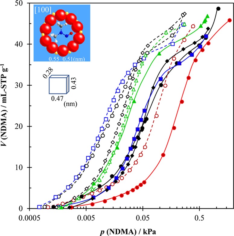
NDMA adsorption isotherms on HSZ(1500) (red ●, red ○), silicalite-1(0) (●, ○), silicalite-1(2CNF-0.75-96) (blue ■, blue □), and silicalite-1(0.25-xCNF-24) with x = 0.1 (green ▲, green Δ) and 0.5 (⧫, ◊). Adsorption temperatures are 318 and 283 K for filled and unfilled marks, respectively. The insets show pore mouth and sizes of the sinusoidal (side-pocket) channel ([100] direction) and the three-dimensional sizes of NDMA.
To understand the adsorption process of NDMA more comprehensively, the isosteric enthalpy of adsorption of NDMA, ΔHiso,NDMA, was calculated by the Clausius–Clapeyron equation.30,31 As shown in Figure 8, except for several peak areas, the values of ΔHiso,NDMA of all of the samples are smaller than the liquefaction enthalpy of NDMA (ΔHliq,NDMA) in the whole adsorption range. This indicates that NDMA molecules receive a very weak adsorption potential in the zeolite pores due to a weaker adsorbate–adsorbent interaction as compared to intermolecular interaction in liquid NDMA. All samples show an increased ΔHiso,NDMA with NDMA adsorption at the initial adsorption stage (<5–10 mL STP g–1), characteristic of the enhanced interadsorbate interaction in zeolitic micropores. The ΔHiso,NDMA of HSZ(1500) reaches a summit (∼39.9 kJ mol–1) at a very small loading of NDMA (∼2.8 mL STP g–1), following which it decreases gradually to a flat stage at 22 kJ mol–1. This evidences cluster formation of the NDMA adsorbates in pores at the very early stage, which possibly impedes the access of the successive NDMA molecules to the internal zeolite pores. On the other hand, no initial peaks of ΔHiso,NDMA are observed for other samples, which, however, do show different levels of adsorption energy at a loading of NDMA below ∼30 mL STP g–1. While ΔHiso,NDMA in this stage approaches a flat area at 31 and 22 kJ mol–1, respectively, for silicalite-1(0) and silicalite-1(0.25-0.5CNF-24), it keeps constant first at a higher value (35.4 kJ mol–1) and then gradually decreases to a second flat stage at 31 kJ mol–1 for silicalite-1(2CNF-0.75-96). It seems reasonable that the different levels of adsorption energy correspond to adsorption of NDMA at different adsorption sites in these zeolites, that is, the main (straight) channel, the sinusoidal (zigzag) channel, and the intersections that they cross. It was reported that preferential adsorption sites in silicalite-1 are dependent on the unique properties of each adsorbate (polarity, linear or bending shape, etc.),38−42 and more investigations are thus required to identify which one of the three adsorption sites is the most energetically favorable or unfavorable for NDMA to be occupied. Nevertheless, the results of the isosteric enthalpy of NDMA strongly support that route A CNF-mediated silicalite-1(2CNF-0.75-96) possesses a very beneficial internal crystal structure for the adsorption of NDMA because its energetically favored adsorption sites are the most easily accessible for NDMA. The reasons contributing to the minimum hindrance can be not only donation of holed or cracked internal structures but also the proportionally reduced twin-type crystal size (Table S1) and formation of smaller crystal subunits (Figures 3 and 5). On the other hand, the difference in adsorption energies of silicalite-1(0) and silicalite-1(0.25-0.5CNF-24) is accountable by their differences in crystal shape parameters (Table S1) and internal silanol defect content, which determine the kind of adsorption site to be occupied by NDMA and different adsorption behaviors of NDMA and MTBE. At the higher loading of NDMA (>∼30 mL STP g–1), all of the synthesized samples show a peak change in ΔHiso,NDMA, characteristic of phase changes of adsorbates in micropores. The phenomenon is corresponding to the step changes in the desorption branch of their adsorption isotherms (Figures S13–S15) and is associated with the framework structure change from the less strained monoclinic phase to the more strained orthorhombic phase.26 This can be confirmed also by comparing XRD patterns before and after adsorption [Figure S16B–G]. In contrast, the phenomenon is more gradual and not as evident for HSZ(1500) (Figures S13a and S16A) as for the synthesized samples. This is further indicative of pore blockage of this sample at the initial adsorption stage, which hinders smooth access of NDMA to other parts of adsorption sites so as hardly to cause the phase change of adsorbates at the higher NDMA loading.
Figure 8.

Isosteric enthalpy of NDMA on HSZ(1500) (◊), silicalite-1(0) (○), silicalite-1(2CNF-0.75-96) (□), and silicalite-1(0.25-0.5CNF-24) (Δ) where the liquefaction enthalpy of NDMA at 298 K, ΔHliq (NDMA) (=36.7 kJ mol–1), is shown.
Conclusions
CNF with nanosized diameter, high aspect ratio, and rich surface hydroxyl groups is proved to be either an excellent emulsifier to obtain uniform and smaller crystal particles or an appropriate mesopore/macropore template depending on synthesis routes and conditions. Route A, which preliminarily mixes CNF with SDA species with an appropriate addition of CNF, promotes the formation of CNF–SDA ion composite structures around which the primary silicate ions are formed and zeolite crystals are subsequently grown. This eventually leads to silicalite-1 with a unique internal holed structure containing mesoporosity and larger pores after the release of CNF. Route B, allowing contact of CNF with silicate–SDA ion seeds, brings about smaller, uniform, well-crystallized but less holed particles and modifies the growth direction of the silicalite-1 crystal.
Besides formation of holes or cracks in a crystal particle, the existence of CNF also modifies the crystal systems of the framework structure in the formed silicalite-1. The orthorhombic part of a silicalite-1 crystal is more likely compartmented near the surface of CNF relative to the monoclinic part and thus adjacent to the surface of the internal holes or cracks for the well-crystallized silicalite-1 sample synthesized by route A.
The content of holes or cracks in a crystal particle plays an important role in overcoming adsorption hindrance to achieve enhanced adsorption because it determines the effectiveness of eliminating diffusion barriers between crystal subunits and platelets. The CNF-mediated holed silicalite-1 by route A possesses an internal crystal structure beneficial for the easy access of adsorbate molecules to energetically preferential adsorption sites, leading to a great adsorption toward both MTBE and NDMA. This becomes possible due to the smaller (proportionally reduced) twin-type crystal size and smaller crystal subunits in addition to the favored short path from internal holes or cracks.
Experimental Section
Materials
Tetrapropylammonium bromide (TPABr) and tetraehtylorthosilicalite (TEOS) of special grades and 1 M sodium hydroxide (NaOH) solution for volumetric analysis were from FUJIFILM Wako Pure Chemical Co. Home-made CNF prepared from commercial cellulose powder (KC Flock W-400, Nippon Paper Chemicals Co., Ltd.) was used. In the preparation of CNF, cellulose powder of 5 wt % was soaked overnight in water and was fibrillated by repeating disk-milling using a super mass colloider (MKCA6-2, Masuko Sangyo Co. Ltd.) at 1800 rpm until a diameter below tens of nanometers.43 The obtained nanosized CNF was confirmed to have a diameter distribution in the range of 20–60 nm by electron microscopic observations.44 A commercial MFI-type zeolite (commercial name: HSZ-890HOA), represented as HSZ(1500), was supplied by Tosoh Co., whose SiO2/Al2O3 molar ratio was as high as 1500 and was used as a reference material.
Synthesis of Holed Silicalite-1
CNF-mediated synthesis of holed silicalite-1 was carried out at the usual synthesis conditions for pure silicalite-145 but under co-existence of CNF. The pure silicalite-1 without addition of CNF, represented as silicalite-1(0), was synthesized at a molar composition of 0.08 NaOH:0.25 TPABr:1 SiO2:11 H2O, where TPABr was used as the SDA species. In a typical synthesis for silicalite-1(0), 2.96 g of TPABr was mixed with 3.55 mL of 1 M NaOH and 5.27 mL of deionized water (D.W.) and the mixture was magnetically stirred at room temperature (RT) for 20 min. After addition of 9.27 g of TEOS, the mixture was stirred at RT for 24 h and then subjected to hydrothermal treatment at 423 K for 24 h. The bottom precipitates were collected by filtration, thoroughly washed with D.W. to neutral pH, and dried at 353 K overnight. After pyrolysis at 823 K in air for 3 h, silicalite-1(0) was obtained.
For the CNF-added synthesis of silicalite-1, CNF was mixed with the synthesis solution for silicalite-1 as an additional component in two different manners. In route A, TPABr was first mixed with a certain amount of CNF solution, to which NaOH was added. The other procedures and conditions were exactly the same as those for silicalite-1(0). The synthesis was carried out at a molar composition of 0.08 NaOH:y TPABr:1 SiO2:11 H2O with x wt % CNF (vs SiO2) added. The parameters x, y, and the hydrothermal treatment time (t) were varied in the synthesis. The obtained zeolites were represented as silicalite-1(xCNF-y-t). In route B, preliminary hydrolysis of TEOS was allowed before mixing with CNF solution. Typically, TEOS was first added into the mixture of TPABr, NaOH, and water at the same molar ratio as that for silicalite-1(0). After continuous stirring at RT for 4 h, x wt % CNF (vs SiO2) was added and the mixture was further stirred at RT for 20 h. The solution was then subjected to hydrothermal treatment at 423 K for 24 h, following which the same procedures and conditions were applied as those for silicalite-1(0). The obtained zeolites were represented as silicalite-1(0.25-xCNF-24) with only x varied in the synthesis.
Characterization
X-ray diffraction (XRD) patterns of samples were measured by a Rigaku SmartLab-type X-ray diffractometer at 40 kV and 30 mA with Cu Kα radiation (λ = 0.15406 nm). Fourier transform infrared (FT-IR) spectra were recorded on a PerkinElmer spectrum 100 Optica type spectrometer, which was equipped with an attenuated total reflection (ATR) attachment having an MKII Golden Gate TM single reflection system consisting of a diamond crystal 45° top plate, a sapphire anvil, and an Optics Unit with ZnSe lenses. FT-IR spectra were also recorded by the KBr-transmission method on a Nicolet NEXUS-470 type spectrometer [under a continuous purge of N2 gas (99.99%)] to achieve higher resolution in the range of 2500–4000 cm–1. Samples (5 wt %) were mixed with KBr (Wako, special grade) to prepare pellets for the measurements. Scanning electron microscopy (SEM) was carried out on either a Hitachi S-4300 type field emission scanning electron microscope (FE-SEM) at an acceleration voltage of 5 kV or a JSM-6010LA type microscope at an acceleration voltage of 15 kV. N2 adsorption isotherms were measured at 77 K on a Belmax volumetric apparatus made MicrotracBEL Co. All of the samples were evacuated at 523 K for 5 h before adsorption measurements. The values of specific surface area, SBET; micropore volume, Vmicro; and total pore volume, Vtotal were calculated by the Brunauer–Emmett–Teller (BET) method at p/p0 < 0.1, the Dubinin–Radushkevich method based on the micropore filling mechanism, and N2 adsorption amount at p/p0 = 0.95, respectively.28,29 The subtraction of Vtotal and Vmicro, Vsb, gives either mesopore or macropore volume or both, which was judged by the shape of isotherms.
Organic Vapor Adsorption
Vapor phase adsorption of MTBE and NDMA was carried out using the same volumetric apparatus in the temperature range of 283–313 K. Before adsorption, samples were degassed sufficiently at RT (usually overnight) and further at 523 K for 3 h. The isosteric enthalpy of adsorption of NDMA, ΔHiso,NDMA, was calculated by the Clausius–Clapeyron equation28,29 from the adsorption isotherms at 283 and 313 K.
Acknowledgments
This work is partially supported by the AIST water project. D.Y. and J.L. thank the China Scholarship Council for providing a scholarship under the State Scholarship Fund (CSC, Nos. 201706240231 and 201608515107). The AIST program for supporting technical training of international exchange student and visiting scholar is gratefully acknowledged.
Supporting Information Available
The Supporting Information is available free of charge on the ACS Publications website at DOI: 10.1021/acsomega.9b00264.
Complete series of XRD patterns (before and after solvent adsorption); FT-IR spectra; SEM images; adsorption isotherms of N2 at 77 K and those of MTBE and NDMA at 283 and 318 K; statistical data on particle size; pore parameter data of all of the samples; ζ-potential data; sample photographs; and schematic drawing on the subunit structure of silicalite-1 (PDF)
The authors declare no competing financial interest.
Supplementary Material
References
- Breck D. W.Zeolite Molecular Sieves, Structure, Chemistry and Use; John Wiley & Sons: New York, 1974. [Google Scholar]
- Barrer R. M.Zeolites and Clay Minerals as Sorbents and Molecular Sieves; Academic Press: London – New York, 1978. [Google Scholar]
- Introduction to Zeolite Science and Practice, 2nd ed.; van Bekkum H., Flanigen E. M., Jacobs P. A., Jansen J. C., Eds.; Elsevier: Amsterdam, 2001; Vol. 137. [Google Scholar]
- Zones S. I. Translating new materials discoveries in zeolite research to commercial manufacture. Microporous Mesoporous Mater. 2011, 144, 1–8. 10.1016/j.micromeso.2011.03.039. [DOI] [Google Scholar]
- Jacobsen C. J.; Madsen C.; Houzvicka J.; Schmidt I.; Carlsson A. Mesoporous zeolite single crystals. J. Am. Chem. Soc. 2000, 122, 7116–7117. 10.1021/ja000744c. [DOI] [Google Scholar]
- Pérez-Ramírez J.; Christensen C. H.; Egeblad K.; Christensen C. H.; Groen J. C. Hierarchical Zeolites: Enhanced Utilisation of Microporous Crystals in Catalysis by Advances in Materials Design. Chem. Soc. Rev. 2008, 37, 2530–2542. 10.1039/b809030k. [DOI] [PubMed] [Google Scholar]
- Na K.; Choi M.; Ryoo R. Recent Advances in the Synthesis of Hierarchically Nanoporous Zeolites. Microporous Mesoporous Mater. 2013, 166, 3–19. 10.1016/j.micromeso.2012.03.054. [DOI] [Google Scholar]
- Silaghi M.-C.; Chizallet C.; Raybaud P. Challenges on Molecular Aspects of Dealumination and Desilication of Zeolites. Microporous Mesoporous Mater. 2014, 191, 82–96. 10.1016/j.micromeso.2014.02.040. [DOI] [Google Scholar]
- Feliczak-Guzik A. Hierarchical Zeolites: Synthesis and Catalytic Properties. Microporous Mesoporous Mater. 2018, 259, 33–45. 10.1016/j.micromeso.2017.09.030. [DOI] [Google Scholar]
- Choi M.; Cho H. S.; Srivastava R.; Venkatesan C.; Choi D. H.; Ryoo R. Amphiphilic Organosilane-Directed Synthesis of Crystalline Zeolite with Tunable Mesoporosity. Nat. Mater. 2006, 5, 718–723. 10.1038/nmat1705. [DOI] [PubMed] [Google Scholar]
- Xiao F.-S.; Wang L.; Yin C.; Lin K.; Di Y.; Li J.; Xu R.-R.; Dang S.-S.; Schlögl R.; Yokoi T.; Tatsumi T. Catalytic Properties of Hierarchical Mesoporous Zeolites Templated with a Mixture of Small Organic Ammonium Salts and Mesoscale Cationic Polymers. Angew. Chem., Int. Ed. 2006, 45, 3090–3093. 10.1002/anie.200600241. [DOI] [PubMed] [Google Scholar]
- Wang L.; Yin C.; Shan Z.; Liu S.; Du Y.; Xiao F.-S. Bread-Template Synthesis of Hierarchical Mesoporous ZSM-5 Zeolite with Hydrothermally Stable Mesoporosity. Colloids Surf., A 2009, 340, 126–130. 10.1016/j.colsurfa.2009.03.013. [DOI] [Google Scholar]
- Wang L.; Zhang Z.; Yin C.; Shan Z.; Xiao F.-S. Hierarchical Mesoporous Zeolites with Controllable Mesoporosity Templated from Cationic Polymers. Microporous Mesoporous Mater. 2010, 131, 58–67. 10.1016/j.micromeso.2009.12.001. [DOI] [Google Scholar]
- Wang R.; Liu W.; Ding S.; Zhang Z.; Li J.; Qiu S. Mesoporous MFI Zeolites with Self-Stacked Morphology Templated by Cationic Polymer. Chem. Commun. 2010, 46, 7418–7420. 10.1039/c0cc02154g. [DOI] [PubMed] [Google Scholar]
- Tao H.; Li C.; Ren J.; Wang Y.; Lu G. Synthesis of Mesoporous Zeolite Single Crystals with Cheap Porogens. J. Solid State Chem. 2011, 184, 1820–1827. 10.1016/j.jssc.2011.05.023. [DOI] [Google Scholar]
- Sabarish R.; Unnikrishnan G. Synthesis, Characterization and Catalytic Activity of Hierarchical ZSM-5 Templated by Carboxymethyl Cellulose. Powder Technol. 2017, 320, 412–419. 10.1016/j.powtec.2017.07.041. [DOI] [Google Scholar]
- Tingaut P.; Zimmermann T.; Sèbe G. Cellulose Nanocrystals and Microfibrillated Cellulose as Building Blocks for the Design of Hierarchical Functional Materials. J. Mater. Chem. 2012, 22, 20105–20111. 10.1039/c2jm32956e. [DOI] [Google Scholar]
- Shao C.; Li X.; Qiu S.; Xiao F.-S.; Terasaki O. Size-Controlled Synthesis of Silicalite-1 Single Crystals in the Presence of Benzene-1,2-diol. Microporous Mesoporous Mater. 2000, 39, 117–123. 10.1016/S1387-1811(00)00183-9. [DOI] [Google Scholar]
- Mallon E. E.; Jeon M. Y.; Navarro M.; Bhan A.; Tsapatsis M. Probing the Relationship between Silicalite-1 Defects and Polyol Adsorption Properties. Langmuir 2013, 29, 6546–6555. 10.1021/la4001494. [DOI] [PubMed] [Google Scholar]
- Dose M. E.; Zhang K.; Thompson J. A.; Leisen J.; Chance R. R.; Koros W. J.; McCool B. A.; Lively R. P. Effect of Crystal Size on Framework Defects and Water Uptake in Fluoride Mediated Silicalite-1. Chem. Mater. 2014, 26, 4368–4376. 10.1021/cm500914b. [DOI] [Google Scholar]
- Lu J.; Xu F.; Wang D.; Huang J.; Cai W. The Application of Silicalite-1/Fly Ash Cenosphere (S/FAC) Zeolite Composite for the Adsorption of Methyl Tert-Butyl Ether (MTBE). J. Hazard. Mater. 2009, 165, 120–125. 10.1016/j.jhazmat.2008.09.090. [DOI] [PubMed] [Google Scholar]
- Damjanović L.; Rakić V.; Rac V.; Stošić D.; Auroux A. The Investigation of Phenol Removal from Aqueous Solutions by Zeolites as Solid adsorbents. J. Hazard. Mater. 2010, 184, 477–484. 10.1016/j.jhazmat.2010.08.059. [DOI] [PubMed] [Google Scholar]
- Jiang N.; Shang R.; Heijman S. G. J.; Rietveld L. C. High-Silica Zeolites for Adsorption of Organic Micro-Pollutants in Water Treatment: A Review. Water Res. 2018, 144, 145–161. 10.1016/j.watres.2018.07.017. [DOI] [PubMed] [Google Scholar]
- Baerlocher C.; McCusker L. B.; Olson D. H.. Atlas of Zeolite Framework Types, 6th ed.; Elsevier: Amsterdam, 2007. [Google Scholar]
- Wu E. L.; Lawton S. L.; Olson D. H.; Rohrman A. C. Jr.; Kokotallo G. T. ZSM-5-Type Materials. Factors Affecting Crystal Symmetry. J. Phys. Chem. A 1979, 83, 2777–2781. 10.1021/j100484a019. [DOI] [Google Scholar]
- van Koningsveld H.; Jansen J. C.; van Bekkum H. The Monoclinic Framework Structure of Zeolite H-ZSM-5. Comparison with the Orthorhombic Framework of As-Synthesized ZSM-5. Zeolites 1990, 10, 235–242. 10.1016/0144-2449(94)90134-1. [DOI] [Google Scholar]
- Barbera K.; Bonino F.; Bordiga S.; Janssens T. V. W.; Beato P. Structure–deactivation relationship for ZSM-5 catalysts governed by framework defects. J Catal. 2011, 280, 196–205. 10.1016/j.jcat.2011.03.016. [DOI] [Google Scholar]
- Hair M. L. Hydroxyl groups on silica surface. J. Non-Cryst. Solids 1975, 19, 299–309. 10.1016/0022-3093(75)90095-2. [DOI] [Google Scholar]
- Iler R. K.The Chemistry of Silica—Solubility, Polymerization. In Colloid and Surface Properties, and Biochemistry; Wiley-Interscience: New York, 1979. [Google Scholar]
- Gregg S. J.; Sing K. S. W.. Adsorption, Surface Area, and Porosity; Academic: New York, 1982. [Google Scholar]
- Rouquerol F.; Rouquerol J.; Sing K. S. W.. Adsorption by Powders & Porous Solids; Academic: San Diego, CA, 1999. [Google Scholar]
- Agger J. R.; Hanif N.; Cundy C. S.; Wade A. P.; Dennison S.; Rawlinson P. A.; Anderson M. W. Silicalite Crystal Growth Investigated by Atomic Force Microscopy. J. Am. Chem. Soc. 2003, 125, 830–839. 10.1021/ja020899f. [DOI] [PubMed] [Google Scholar]
- Roeffaers M. B. J.; Ameloot R.; Bons A. J.; Mortier W.; Cremer G. D.; de Kloe R.; Hofkens J.; De Vos D. E.; Sels B. F. Relating Pore Structure to Activity at the Subcrystal Level for ZSM-5: An Electron Backscattering Diffraction and Fluorescence Microscopy Study. J. Am. Chem. Soc. 2008, 130, 13516–13517. 10.1021/ja8048767. [DOI] [PubMed] [Google Scholar]
- Karwacki L.; Kox M. H. F.; deWinter D. A. M.; Drury M. R.; Meeldijk J. D.; Stavitski E.; Schmidt W.; Mertens M.; Cubillas P.; John N.; Chan A.; Kahn N.; Bare S. R.; Anderson M.; Kornatowski J.; Weckhuysen B. M. Morphology-dependent zeolite intergrowth structures leading to distinct internal and outer-surface molecular diffusion barriers. Nat. Mater. 2009, 8, 959–965. 10.1038/nmat2530. [DOI] [PubMed] [Google Scholar]
- Brabec L.; Kocirik M. Silicalite-1 Crystals Etched with Hydrofluoric Acid Dissolved in Water or Acetone. J. Phys. Chem. C 2010, 114, 13685–13694. 10.1021/jp1027228. [DOI] [Google Scholar]
- Lupulescu A. I.; Rimer J. D. In Situ Imaging of Silicalite-1 Surface Growth Reveals the Mechanism of Crystallization. Science 2014, 344, 729–732. 10.1126/science.1250984. [DOI] [PubMed] [Google Scholar]
- Sprung C.; Weckhuysen B. M. Differences in the Location of Guest Molecules within Zeolite Pores As Revealed by Multilaser Excitation Confocal Fluorescence Microscopy: Which Molecule Is Where?. J. Am. Chem. Soc. 2015, 137, 1916–1928. 10.1021/ja511381f. [DOI] [PMC free article] [PubMed] [Google Scholar]
- Fujiyama S.; Seino S.; Kamiya N.; Nishi K.; Yokomori Y. Adsorption structure of dimethyl ether on silicalite-1 zeolite determined using single-crystal X-ray diffraction. Acta Crystallogr., Sect. B: Struct. Sci., Cryst. Eng. Mater. 2014, 70, 856–863. 10.1107/S2052520614015911. [DOI] [PMC free article] [PubMed] [Google Scholar]
- Fujiyama S.; Seino S.; Kamiya N.; Nishi K.; Yoza K.; Yokomori Y. Adsorption Structures of Non-Aromatic Hydrocarbons on Silicalite-1 Using the Single-Crystal X-ray Diffraction Method. Phys. Chem. Chem. Phys. 2014, 16, 15839–15845. 10.1039/C4CP01860E. [DOI] [PubMed] [Google Scholar]
- Fujiyama S.; Kamiya N.; Nishi K.; Yokomori Y. Adsorption Process of CO2 on Silicalite-1 Zeolite Using Single-Crystal X-ray Method. Langmuir 2014, 30, 3749–3753. 10.1021/la404962e. [DOI] [PubMed] [Google Scholar]
- van Koningsveld H.; Jansen J. C.; de Man A. J. M. Single-Crystal Structure Analysis and Energy Minimizations of a MFI-Type Zeolite at Low p-Dichlorobenzene Sorbate Loading. Acta Crystallogr., Sect. B: Struct. Sci., Cryst. Eng. Mater. 1996, 52, 131–139. 10.1107/S0108768195008512. [DOI] [Google Scholar]
- Kamiya N.; Iwama W.; Kudo T.; Nasuno T.; Fujiyama S.; Nishi K.; Yokomori Y. Determining the Structure of a Benzene 7.2- silicalite-1 zeolite Using a Single-Crystal X-ray Method. Acta Crystallogr., Sect. B: Struct. Sci., Cryst. Eng. Mater. 2011, 67, 508–515. 10.1107/S0108768111038560. [DOI] [PMC free article] [PubMed] [Google Scholar]
- Kumagai A.; Lee S. H.; Endo T. Thin film of lignocellulosic nanofibrils with different chemical composition for QCM-D Study. Biomacromolecules 2013, 14, 2420–2426. 10.1021/bm400553s. [DOI] [PubMed] [Google Scholar]
- Wu H.; Wang Z.-M.; Kumagai A.; Endo T. Amphiphilic cellulose nanofiber-interwoven graphene aerogel monolith for dyes and silicon oil removal. Compos. Sci. Technol. 2019, 171, 190–198. 10.1016/j.compscitech.2018.12.017. [DOI] [Google Scholar]
- Lai S. M.; Au L. T. Y.; Yeung K. L. Influence of the Synthesis Conditions and Growth Environment on MFI Zeolite Film Orientation. Microporous Mesoporous Mater. 2002, 54, 63–77. 10.1016/S1387-1811(02)00341-4. [DOI] [Google Scholar]
Associated Data
This section collects any data citations, data availability statements, or supplementary materials included in this article.