Abstract
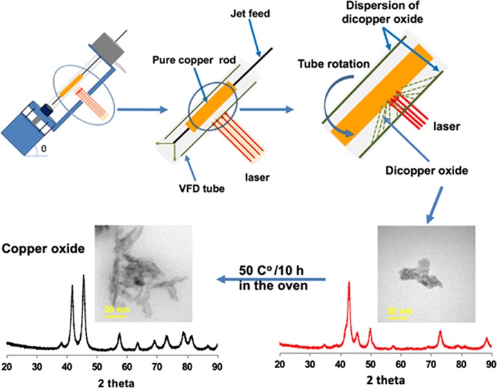
Copper(I) oxide (Cu2O) nanoparticles (NPs) are selectively prepared in high yields under continuous flow in a vortex fluidic device (VFD), involving irradiation of a copper rod using a pulsed laser operating at 1064 nm and 600 mJ. The plasma plume generated inside a glass tube (20 mm O.D.), which is rapidly rotating (7.5 k rpm), reacts with the enclosed air in the microfluidic platform, with then high mass transfer of material into the dynamic thin film of water passing up the tube. The average size of the generated Cu2ONPs is 14 nm, and they are converted to copper(II) oxide (CuO) nanoparticles with an average diameter of 11 nm by heating the as-prepared solution of Cu2ONPs in air at 50 °C for 10 h.
Introduction
The physical and chemical properties of nanoparticles of metal oxides are distinctly different to bulk materials, and they are attracting considerable attention. They find applications in diverse fields, including chemical manufacturing, environmental technology, energy conversion, and storage as well as in biological areas.1−4 A diversity of techniques have been used to prepare metal oxide particles in general, including electrophoretic and electrochemical deposition,5 vacuum deposition,6 sonochemical processing,7 lithography, and diffusion-controlled nanoparticle growth.8 Focusing on dicopper oxide (Cu2O) and copper oxide (CuO), they have been prepared using such techniques, with the uniform size and shape of the particles.7,8 They find particular use in catalytic organic transformations, electrocatalysis, and photocatalysis.9−11 Developing synthetic methodologies and supports that increase the stability of copper nanoparticles have been explored, especially in regard to their sensitivity to oxygen, water, and different reagents. This has led to the development of more complex-structured nanoparticles, as in core–shell particles, and different ways to oxidize the copper.12
Batch processing is typically used in the fabrication of copper oxide nanoparticles, but such processing can result in variation of product from batch to batch, and refined reagents are required. An alternative approach to prepare different metal oxides in general involves the use of lasers, and this includes in the synthesis of copper oxide nanoparticles.13−17 Pulsed laser ablation (PLA) involves ablating a solid target in a liquid phase or in air, which has a number of advantages. These include (a) not requiring the process to be operating under a high vacuum, (b) the processing is simple and high yielding, and (c) it avoids the use of chemicals. In addition, optimizing the experimental parameters can result in controlling the shape and size of the nanoparticles.17 PLA involves absorption of the laser radiation at the metal surface as the so-called interaction zone, which causes the transformation of kinetic energy into thermal energy. Also, if the laser power is sufficiently high, a local plasma plume with high temperatures and pressures is formed,18 and this can lead to the formation of metal oxide particles in the presence of oxygen.
We report the synthesis of copper(I) oxide nanoparticles using PLA under continuous flow conditions, which can minimize batch variation in the process, as discussed above. Continuous flow processing is important in being able to scale up from the research laboratory processing to large-scale production, thereby avoiding batch-to-batch variation, which can occur for traditional processing while minimizing capital outlay, with built in just-in-time production.19 The synthesis featured the use of the vortex fluidic device (VFD) as a dynamic thin film microfluidic processing platform, Figure 1. The relatively inexpensive VFD houses a borosilicate glass tube (20 mm O.D.,17.5 mm I.D.), open at one end, which is rotated at high speed (up to 9 k rpm) and can be inclined from 0 to 90° relative to the horizontal position.19−21 It has two common modes of operation as follows: (i) the confined mode where a finite volume of liquid is added to the rapidly rotating tube, and (ii) the continuous flow mode where liquid is constantly fed into the tube usually as droplets. Under the centrifugal force, the liquid whirls up and exits at the top of the tube, and this continuous flow mode of operation of the VFD offers scalability to the processing by simply extending the operating time.22−24 Applications of the VFD also include enhancing enzymatic reactions,19 controlling organic synthesis,20,25 probing the structure of self-organized systems,26 protein separation,27 exfoliation of 2D graphite and boron nitride,21 protein folding,28 and more,23,29−31Figure 1. Herein, we have established that the VFD is selective in forming copper(I) oxide (Cu2O) NPs with an average particle size of 14 nm in diameter, as a one-step continuous flow process at ambient pressure, with the oval operation avoiding a purification step. The process can also minimize the generation of waste, in avoiding the need for adding any reagents, although specific surfactants can be added at the end of the processing if required. Using an aqueous solution and avoiding harsh chemicals impart high in green chemistry metrics into the processing and developing more sustainable processing for the future.27Figure 2 is a zoomed-in representation of the operation of the VFD in generating Cu2ONPs when the laser strikes the copper metal rod inside the rapidly rotating glass tube. The confined mode was initially used to establish optimal conditions for generating the Cu2ONPs, before applying these conditions to continuous flow. This approach has been used for a number of applications of the VFD in translating the processing into continuous flow. Heating solutions of the generated copper(I) oxide particles, Cu2ONPs, in water results in conversion to nanoparticles of copper(II) oxide, CuONPs. We note that the VFD is effective in being able to control the size and shape of nanoparticles, for example, superparamagnetic magnetite nanoparticales.23 In the context of copper oxide nanoparticles, this is important for downstream applications, for example, in gas sensors, magnetic phase transition, superconductors, and catalysts.32,33
Figure 1.
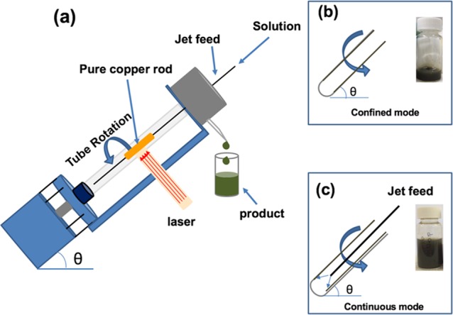
(a) Diagrammatic representation of the VFD with a pure copper rod inside the glass tube (20 mm O.D., 17.5 mm I.D.) spun at 7.5 k rpm and irradiated with a 5 ns-pulsed Nd:YAG laser operating at 1064 nm and 600 mJ, having a 8 mm-diameter beam, (b) confined mode of operation of the VFD, for 15 min, and (c) continuous flow mode of operation at a flow rate of water at 0.25 mL/min.
Figure 2.
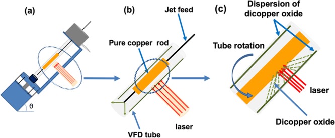
(a) VFD showing the position of the pure copper rod as the laser target. (b, c) Zoomed-in arrangement of the tube and the irradiation of the copper rod.
Results and Discussion
Copper(I) oxide (Cu2O) nanoparticles were selectively formed in the VFD under different operating conditions of the device, with this material readily converted to copper(II) oxide (CuO) nanoparticles post VFD processing by gentle heating in air. The optimization experiments were initially carried out in the confined mode of operation of the VFD, for a 15 min processing time, with 1 mL of Milli-Q water inside the rapidly rotating tube. The tilt angles of all the experiments were set at 45°, which has been established as optimal setting for many applications of the device.23,24,34 The effect of choice of laser power was then explored, using 450, 550, 600, and 650 mJ. For the lowest power, no product could be isolated, with a low yield obtained at 550 mJ. In contrast, high yields were obtained for 600 and 650 mJ, and accordingly, 600 mJ was chosen as optimal setting in being cognizance of minimizing energy usage in developing processing high in green chemistry metrics. The next operating parameter to be optimized was the rotational speed of the tube, and to this end, we carried out laser ablation experiments at 4.5 k, 5.5 k, 6.5 k, 7.5 k, and 8.5 k rpm. XRD was used as the primarily characterization technique for the resulting Cu2ONPs. The rotational speeds of 4.5 k, 5.5 k, and 6.5 k rpm gave diameters of 19 nm ± 2 nm, whereas 8.5 k rpm gave 17 nm ± 1 nm particles, and 7.5 k rpm gave 14 nm ± 1 nm diameter particles, Figure S2b. Moreover, the XRD for material generated at 4.5 k, 5.5 k, 6.5 k, and 8.5 k rpm showed increasing amount of CuONPs relative to 7.5 k rpm, and this was chosen as the optimum speed. Overall, the confined mode experiments established the optimal power setting of the laser and optimal rotation speed while minimizing the amount of conversion of Cu2ONPs to CuONPs.
The flow rate of Milli-Q water into the VFD was then optimized, for 1, 0.75, 0.5, 0.25, and 0.1 mL/min flow rates. The 1, 0.75, 0.5, and 0.1 mL/min flow rates resulted in a higher percentage of CuONPs relative to 0.25 mL/min, Figure S2c, and this flow rate was then considered as optimal for preparing Cu2ONPs. Thus, the overall optimized conditions were at a laser power of 600 mJ, a rotational speed of 7.5 k rpm, and with a flow rate of 0.25 mL/min. Water was used to dilute the solution, necessitating the drying of the product, Figure S2c and Figures 3 and 4. The copper rod showed visible etching and blackening post laser ablation experiments.
Figure 3.
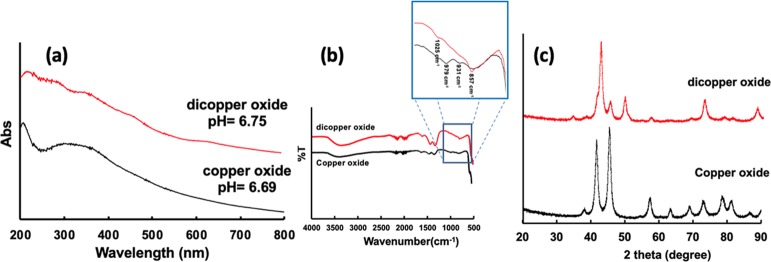
(a) UV–vis spectra, (b) ATR-FTIR, and (c) X-ray diffraction patterns for Cu2ONP prepared in a VFD under continuous flow of water at a flow rate of 0.25 mL/min with the tube inclined at 45°, rotating at 7.5 k rpm, and irradiated with a 1064 nm-pulsed laser operating at 600 mJ. Analogous data were obtained for CuONPs prepared from a dispersion of Cu2ONPs heated to 50 °C for 10 h.
Figure 4.
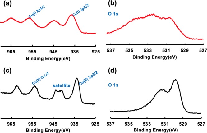
(a, b) XPS for copper and oxygen in Cu2ONPs prepared in a VFD under continuous flow of water (0.25 mL/min) with the glass tube inclined at 45° and rotating at 7.5 k rpm, with the 1064 nm wavelength pulsed laser operating at 600 mJ. (c, d) XPS for copper and oxygen in CuONPs prepared from Cu2ONPs dispersion after heating in air inside the oven at 50 °C for 10 h.
The pH of water used for the experiment was 6.90, but immediately after the VFD processing, it was slightly lower at 6.75, with the solution containing a dispersion of Cu2ONPs. After heating the solution at 50 °C for 10 h in an oven, the pH decreased slightly to 6.69, with the NPs converted to CuO. ATR-FTIR spectra established the presence of Cu2ONPs and CuONPs, with a broad peak at 3400 cm–1 corresponding to an O–H stretching vibration band and 1628 cm–1 bending vibration of water and surface-bound hydroxyl moieties.35,36 Two peaks in the fingerprint region, at 1025 and 857 cm–1, correspond to bending vibrations for surface-bound hydroxyl moieties.36 Any CuO present was identified by peaks at 979 and 931 cm–1 as well as at 597 cm–1, which corresponds to Cu–O vibrations, Figure 3b.35,37−40 UV–vis spectra could be used to differentiate between Cu2ONPs and CuONPs, with solutions of the pure components taking on clear light green and light brown solutions, respectively.41−43 A clear brown solution of CuONPs44 was prepared after heating a Cu2ONP solution in air at 50 °C for 10 h. Figure 3a shows a color change from green to brown in accordance with the change of band gap energy between Cu2ONPs and CuONPs. The presence of the different copper oxide structures was established using XRD, at the same time providing the average particle size of the isolated materials using the Scherrer equation. The XRD pattern (Co Kα, λ = 1.7889 Å) was devoid of peaks for elemental copper, ruling out the formation of a core–shell structure such as Cu@Cu2O,45,46 but with peaks corresponding to Cu2O, at 34.8, 42.7, 49.6, 62.2, 72.9, and 88.1°, Figure 3c.46−50 The Cu2O diffraction pattern had peaks at 2θ of 34.8, 42.7, 49.6, 62.2, 72.9, and 88.1°, corresponding to (110), (111), (200), (211), (220), and (311) for cubic cuprite, respectively.46−50 In addition, there were small peaks assigned to the presence of some CuO, presumably arising from some oxidation during the workup immediately post VFD processing. The peaks for CuONPs are at 2θ of 38.2, 41.6, 45.4, 54.3, 57.4, 63.5, 68.9, 73, 78.6, 81.3, and 86.7°, corresponding to (110), (111), (111), (112), (202), (020), (202), (113), (002), (311), and (220), respectively. Heating the Cu2NPs at 50 °C for 10 h gave sharp peaks corresponding to the diffraction pattern for exclusively CuO, Figure 3c.51,52 The size of the Cu2ONPs was estimated from the Scherrer equation to be 14 ± 1 nm and the size of the CuONPs at 11 ± 1 nm.
The mechanism of forming the nanoparticles by laser irradiation of copper metal in the VFD involves creating Cu2ONPs in the air in the VFD tube, Figure S6. The metal rod contains no copper oxide, and thus, the oxygen is from the air. Moreover, the thermal energy delivered to the surface of the copper target creates a plume of copper, which reacts with oxygen in the air, resulting in the formation of Cu2ONPs, and this is reflected in a change of color of the liquid from colorless to green48,49 during the processing. When a pure nitrogen gas atmosphere was used in the VFD, as a control experiment, no oxidation was evident, and there was no change in color of the water, Figure S6. Thus, oxygen in the air is the reactive species in forming Cu2ONPs. The time and temperature with oxygen from air were keys to convert Cu2ONPs to CuONPs, Figure S5.53,54 It is also noteworthy that there was no evidence for the formation of core–shell Cu@CuO2NPs or indeed any particles based on elemental copper (XPS and XRD). The need for a partial pressure of oxygen gas is also evident by the formation of Cu2ONPs in toluene or isopropyl alcohol (IPA), Figure S4, but these reactions were not pursued further given that the focus of the research is on developing processes that are high in green chemistry metrics, in avoiding the generation of an organic solvent waste stream and the formation of metal carbide nanoparticles.
According to the literature, the binding energies of Cu(I) by XPS are at about 936.5 and 956.5 eV for Cu 2p3/2 and Cu 2p1/2, respectively. On the other hand, XPS energies for Cu (II) are shifted to about 934 and 954 eV for Cu 2p3/2 and Cu 2p1/2, respectively. Furthermore, the CuONP spectrum had two extra peaks at 941.2 and 943.7 eV. These correspond to the relative intensities of the shake-up satellites on the surface of the material, Figure 4a,c. Moreover, the XPS spectra for O1s in Cu2O and CuO were distinctly different with the O1s in CuO shifting from 534.5 and 532.4 eV to 531.3 and 529.7 eV, respectively, Figure 4b,d.55−58 The XPS results are also consistent with the sample being devoid of elemental copper, as for example in Cu@Cu2O, being devoid of the Cu(0) peak at 932 eV and associated shake-up satelites,59Figure 4a. The XPS spectrum for Cu2ONPs has peaks at about 936.5 and 956.5 eV, representing Cu 2p3/2 and Cu 2p1/2, respectively. The shake-up satellites are at around 944.1 eV with the shake-up satellites for the CuONPs are at 941.2 and 943.7 eV.55−58
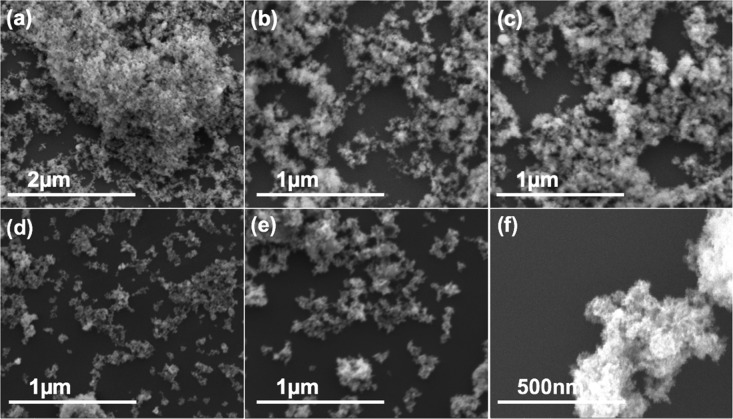
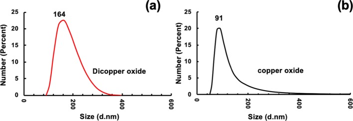
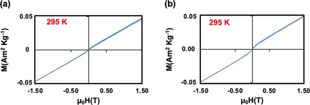
The morphology, size, and shape of Cu2ONPs and CuONPs were investigated by SEM, AFM, and TEM, respectively. Both nanoparticles were shown to have a similar topography and were aggregated. The size of the nanoparticles was established using XRD and SEM, Figure 5 and Figures S7 and S8. AFM images gave information on the size of the nanoparticles, Figure 7. In addition, TEM images for both Cu2ONPs and CuONPs provided more details about the size and shape of the nanoparticles, showing a different shape for each structure, Figure 6 and Figure S9. Dynamic light scattering (DLS) on both Cu2ONPs and CuONPs in solution established the presence of agglomerates, 164 and 91 nm diameters for Cu2ONPs and CuONPs, respectively, Figure 8. The sizes of Cu2ONPs and CuONPs were measured for about 200 particles from TEM images. These showed size estimations similar to those from the Scherrer equation for the bulk material, Figure 9. Magnetization data was collected for CuONPs, showing an essentially linear (paramagnetic) response versus applied field to 1.5 T, with a hint of ferromagnetism at very low fields. The results are consistent with the previous measurements by Punnoose et al.60 both in terms of the form and magnitude of the magnetization. From Figure 10, it can be seen that magnetization is 0.0473 (Am2 Kg–1) at room temperature and 1.5 T for CuONPs collected from outside the VFD tube and 0.0482 M (Am2 Kg–1) for particles from inside the VFD tube. These values of magnetization for the ≈11 nm NPs of this work are slightly smaller than those recorded at room temperature and 1.5 T for 6.6 nm NPs by Punnoose et al.60 in line with the magnetization versus particle size trends of their work.
Figure 5.
(a)–(c) SEM images of Cu2ONPs formed using a VFD operating under continuous flow of water at 0.25 mL/min, with the glass tube at a 45° tilt angle and rotating at 7.5 k rpm, using a 1064 nm-pulsed laser operating at 600 mJ, irradiating a pure copper target. (d)–(f) CuONPs after heating in the as-prepared solutions at 50 °C for 10 h. Samples were prepared using drop casting on a silicon wafer.
Figure 7.
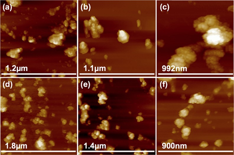
(a)–(c) AFM images of Cu2ONPs formed using a VFD operating under continuous flow of water at 0.25 mL/min, with the glass tube at a 45° tilt angle and rotating at 7.5 k rpm, using a 1064 nm pulsed laser operating at 600 mJ, irradiating a pure copper target. (d)–(f) CuONPs after heating the as-prepared solutions at 50 °C for 10 h. Samples were prepared using drop casting on a silicon wafer.
Figure 6.
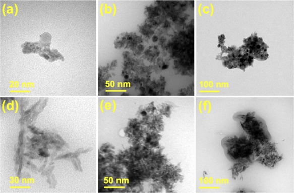
(a)–(c)TEM images of Cu2ONPs formed using a VFD operating under continuous flow of water at 0.25 mL/min, with the glass tube at a 45° tilt angle and rotating at 7.5 k rpm, using a 1064 nm pulsed laser operating at 600 mJ, irradiating a pure copper target. (d)–(f) CuONPs after heating the as-prepared solutions at 50 °C for 10 h. Samples were prepared using drop casting on a grid.
Figure 8.
(a, b) DLS of material redispersed in water. (a) Cu2ONPs formed in the VFD with the glass tube at a 45° tilt angle and rotating at 7.5 k rpm, flow rate of water 0.25 mL/min, and the 1064 nm pulsed laser operating at 600 mJ and irradiating a copper target. (b) CuONPs formed after heating the Cu2ONPs suspension in air at 50 °C for 10 h.
Figure 9.
(a, b) Size estimation of nanoparticles using TEM images, for (a) material generated in a VFD with the glass tube at a 45° tilt angle and rotating at 7.5 k rpm, flow rate of water 0.25 mL/min, and the 1064 nm-pulsed laser operating at 600 mJ and irradiating a copper target, and (b) CuONPs prepared from a Cu2ONPs dispersion in water after heating at 50 °C for 10 h in an oven.
Figure 10.
(a, b)Magnetization data for CuONPs formed under continuous flow in the VFD flow of water at 0.25 mL/min, a 45° tilt angle, using a 1064 nm pulsed laser operating at 600 mJ and irradiating a copper target followed by heating the material as solution at 50 °C for 10 h in an oven. (a) Material from the solution exiting the tube. (b) Material collected from inside the tube after 2 h of processing.
Conclusions
Cu2ONPs were prepared by pulsed laser irradiation of a pure copper rod positioned inside a VFD tube, with the material readily converted to copper(II) oxide on mild heating in solution. The NPs are created in situ, in a continuous flow process, using water as the choice for solvent. TEM images and XRD data incorporating the use of the Scherrer equation established the presence of nanometer-sized particle, with the mechanism of formation of Cu2ONPs involving oxidation of copper in air above the thin film of liquid in the VFD. The new method of the synthesis of these NPs is simple and in high yield, using metal as the source of copper, at the same time avoiding the use of harsh chemicals or agents using water as the choice for solvent,23,24 and the scene is set for using this method for generating oxides of other metals.
Overall, the overall novelty of this work is the ability to selectively prepare relatively small Cu2ONPs from elemental copper, using a process that can minimize the generation of waste, and this is possible using the VFD thin-film microfluidic platform. Also, it is noteworthy to note that the Cu2ONPs are readily converted to small CuONPs by mild heating, and that selectively forming Cu2ONPs in water using laser processing is challenging,17,23 being difficult to scale and control the homogeneity, with long ablation times resulting mainly in the formation of larger particles.
In exploring the applicability of the process for scaling up, we prepared 200 mg of Cu2ONPs, as a powder, over 12 h for a single pass through the VFD. In addition, we prepared 200 mg of CuONPs as a powder, from heating a suspension of 200 mg of Cu2ONPs in water at 50 °C. This augurs well for the potential application of the copper(I and II) oxide NPs.1−4
Experimental Section
Materials
A high purity (>99.998%) 8361 h copper metal rod of 8 mm in diameter (Koch-Light Laboratories Ltd. Colnbrook Bucks, England) was used for all the processing. Milli-Q water was used.
Synthesis of Cu2O and CuO
Nanoparticles of Cu2O were generated in the dynamic thin film in the VFD tube (borosilicate glass tube of 20 mm O.D., 17.5 mm I.D., and 19.5 cm in length) on irradiating a stationary pure copper rod (>99.998%) located in the middle of the tube. The laser used was generated from a Nd:YAG source, as a pulsed source operating at 1064 nm and 600 mJ/pulse. The laser was operated unfocussed, with a beam diameter of 8 mm, giving a fluence of 1.2 J cm–2. Under continuous flow, water was delivered via a jet feed to the base of the tube, with a flow rate setting of 0.25 mL/min, and for confined mode, 1 mL of liquid was added to the tube with the experiment run for 15 min. The rotational speed for the glass tube in the VFD was 7.5 k rpm, with the tube titled at 45° relative to the horizontal position. The product from confined mode and continuous flow was Cu2ONPs dispersed in water. The method used to collect the product after 90 min was as follows: approximately 20 mL of solution, Figure S5a, was centrifuged at RCF = 9980 g for 20 min; whereupon, the supernatant was removed, and the pellet was redispersed in 5 mL of acetone, followed by centrifugation at RCF = 4000 g for 10 min. The supernatant was then removed, and the pellet was left to air dry for 5 min. This method was effective in rapidly removing the water and collecting the Cu2ONPs as a powder. This powder was then stored in a sealed vial, taking care to exclude oxygen in avoiding oxidizing the material to CuONPs, which was shown to occur after 1 week. For each 1 mL of the original solution from the continuous flow process, approximately 0.8 mg of product was collected. The method used to deliberately prepare CuONPs was to heat a dispersion of the Cu2ONPs from the continuous flow process in an oven at 50 °C for 10 h as shown in Figure S5b. The water was then removed under reduced pressure (rotary evaporator), affording a brown powder, which was stable in air. The same steps were used to isolate the product remaining in the tube after continuous flow processing. On completing the experiment, the material remaining in the VFD tube was shown to be Cu2ONPs. This was collected from inside the VFD tube after 2 h of processing using the same above method, Figure S4e. Approximately 15 mg of Cu2ONPs was collected inside the VFD, post processing. Cu2ONPs collected from inside the VFD tube after 2 h using 15 mL of water afforded approximately 15 mg of the material.
Characterization
The nanoparticles were characterized using scanning electron microscopy (SEM, Inspect FEI F50), atomic force microscopy (AFM, Nanoscope 8.10 tapping mode), X-ray photoelectron spectroscopy (XPS, Kratos Axis Ultra, with a monochromatic Al Ka X-ray source), XRD (Bruker D8 ADVANCE ECO, Co Kα, λ = 1.7889 A), ATR-FTIR (Perkin Elmer Frontier), UV–vis spectroscopy (Agilent technologies Cary 60 Uv–vis), and TEM (Tecnai_G2_Spirit). Particles were collected using a centrifuge (Dynamica VELOCITY 14R). Magnetization measurements were carried out using a Quantum design MPMS at 295 K in the field range ± 1.50 T.
Acknowledgments
The authors gratefully acknowledge financial support from the Iraq Government, Ministry of Higher Education and Scientific Research, and the Australian Research Council and the Government of South Australia. Use of facilities in the Australian Microscopy & Microanalysis Research Facility (AMMRF) and the Australian National Fabrication Facility (ANFF) at the South Australian nodes of the AMMRF and ANFF under the National Collaborative Research Infrastructure Strategy are also acknowledged, along with assistance from Dr. Jason Gascooke in collecting SEM images and Mr. Scott Pye for discussions and proof reading.
Supporting Information Available
The Supporting Information is available free of charge on the ACS Publications website at DOI: 10.1021/acsomega.9b01983.
Additional characterization data including XRD and SEM (PDF)
The authors declare no competing financial interest.
Supplementary Material
References
- Laurent S.; Forge D.; Port M.; Roch A.; Robic C.; Vander Elst L.; Muller R. N. Magnetic Iron Oxide Nanoparticles: Synthesis, Stabilization, Vectorization, Physicochemical Characterizations, and Biological Applications. Chem. Rev. 2008, 108, 2064–2110. 10.1021/cr068445e. [DOI] [PubMed] [Google Scholar]
- Sowani H.; Mohite P.; Damale S.; Kulkarni M.; Zinjarde S. Carotenoid stabilized gold and silver nanoparticles derived from the Actinomycete Gordonia amicalis HS-11 as effective free radical scavengers. Enzyme Microb. Technol. 2016, 95, 164–173. 10.1016/j.enzmictec.2016.09.016. [DOI] [PubMed] [Google Scholar]
- Vijayan S. R.; Santhiyagu P.; Ramasamy R.; Arivalagan P.; Kumar G.; Ethiraj K.; Ramaswamy B. R. Seaweeds: a resource for marine bionanotechnology. Enzyme Microb. Technol. 2016, 95, 45–57. 10.1016/j.enzmictec.2016.06.009. [DOI] [PubMed] [Google Scholar]
- Suriani A. B.; Dalila A. R.; Mohamed A.; Mamat M. H.; Malek M. F.; Soga T.; Tanemura M. Fabrication of vertically aligned carbon nanotubes–zinc oxide nanocomposites and their field electron emission enhancement. Mater. Des. 2016, 90, 185–195. 10.1016/j.matdes.2015.10.051. [DOI] [Google Scholar]
- Golden T. D.; Shumsky M. G.; Zhou Y.; VanderWerf R. A.; Van Leeuwen R. A.; Switzer J. A. Electrochemical Deposition of Copper(I) Oxide Films. Chem. Mater. 1996, 8, 2499–2504. 10.1021/cm9602095. [DOI] [Google Scholar]
- Korotcenkov G. Gas response control through structural and chemical modification of metal oxide films: state of the art and approaches. Sens. Actuators, B 2005, 107, 209–232. 10.1016/j.snb.2004.10.006. [DOI] [Google Scholar]
- Kumar R. V.; Diamant Y.; Gedanken A. Sonochemical Synthesis and Characterization of Nanometer-Size Transition Metal Oxides from Metal Acetates. Chem. Mater. 2000, 12, 2301–2305. 10.1021/cm000166z. [DOI] [Google Scholar]
- Guo Q.; Teng X.; Rahman S.; Yang H. Patterned Langmuir–Blodgett Films of Monodisperse Nanoparticles of Iron Oxide Using Soft Lithography. J. Am. Chem. Soc. 2003, 125, 630–631. 10.1021/ja0275764. [DOI] [PubMed] [Google Scholar]
- Allen S. E.; Walvoord R. R.; Padilla-Salinas R.; Kozlowski M. C. Aerobic copper-catalyzed organic reactions. Chem. Rev. 2013, 113, 6234–6458. 10.1021/cr300527g. [DOI] [PMC free article] [PubMed] [Google Scholar]
- Yin G.; Nishikawa M.; Nosaka Y.; Srinivasan N.; Atarashi D.; Sakai E.; Miyauchi M. Photocatalytic Carbon Dioxide Reduction by Copper Oxide Nanocluster-Grafted Niobate Nanosheets. ACS Nano 2015, 9, 2111–2119. 10.1021/nn507429e. [DOI] [PubMed] [Google Scholar]
- Poreddy R.; Engelbrekt C.; Riisager A. Copper oxide as efficient catalyst for oxidative dehydrogenation of alcohols with air. Catal. Sci. Technol. 2015, 5, 2467–2477. 10.1039/C4CY01622J. [DOI] [Google Scholar]
- Gawande M. B.; Goswami A.; Felpin F.-X.; Asefa T.; Huang X.; Silva R.; Zou X.; Zboril R.; Varma R. S. Cu and Cu-based nanoparticles: synthesis and applications in catalysis. Chem. Rev. 2016, 116, 3722–3811. 10.1021/acs.chemrev.5b00482. [DOI] [PubMed] [Google Scholar]
- Tsuji T.; Iryo K.; Watanabe N.; Tsuji M. Preparation of silver nanoparticles by laser ablation in solution: influence of laser wavelength on particle size. Appl. Surf. Sci. 2002, 202, 80–85. 10.1016/S0169-4332(02)00936-4. [DOI] [Google Scholar]
- Amikura K.; Kimura T.; Hamada M.; Yokoyama N.; Miyazaki J.; Yamada Y. Copper oxide particles produced by laser ablation in water. Appl. Surf. Sci. 2008, 254, 6976–6982. 10.1016/j.apsusc.2008.05.091. [DOI] [Google Scholar]
- Gondal M.; Qahtan T. F.; Dastageer M.; Saleh T. A.; Maganda Y. W.. Synthesis and characterization of copper oxides nanoparticles via pulsed laser ablation in liquid In High Capacity Optical Networks and Enabling Technologies (HONET-CNS), 2013 10th International Conference on, IEEE: 2013; pp 146–150. [Google Scholar]
- Markert J. T.; Messina T. C.; Dam B.; Huijbregste J.; Rector J. H.; Griessen R. Infinite-layer copper-oxide laser-ablated thin films: substrate, buffer-layer, and processing effects. IEEE Trans. Appl. Supercond. 2003, 13, 2684–2686. 10.1109/TASC.2003.811956. [DOI] [Google Scholar]
- Haram N.; Ahmad N. Effect of laser fluence on the size of copper oxide nanoparticles produced by the ablation of Cu target in double distilled water. Appl. Phys. A: Mater. Sci. Process. 2013, 111, 1131–1137. 10.1007/s00339-012-7329-0. [DOI] [Google Scholar]
- Vitta Y.; Piscitelli V.; Fernandez A.; Gonzalez-Jimenez F.; Castillo J. α-Fe nanoparticles produced by laser ablation: Optical and magnetic properties. Chem. Phys. Lett. 2011, 512, 96–98. 10.1016/j.cplett.2011.07.020. [DOI] [Google Scholar]
- Britton J.; Chalker J. M.; Raston C. L. Rapid Vortex Fluidics: Continuous Flow Synthesis of Amides and Local Anesthetic Lidocaine. Chem. – Eur. J. 2015, 21, 10660–10665. 10.1002/chem.201501785. [DOI] [PubMed] [Google Scholar]
- Gandy M. N.; Raston C. L.; Stubbs K. A. Towards aryl C-N bond formation in dynamic thin films. Org. Biomol. Chem. 2014, 12, 4594–4597. 10.1039/c4ob00926f. [DOI] [PubMed] [Google Scholar]
- Chen X.; Dobson J. F.; Raston C. L. Vortex fluidic exfoliation of graphite and boron nitride. Chem. Commun. 2012, 48, 3703–3705. 10.1039/c2cc17611d. [DOI] [PubMed] [Google Scholar]
- Alharbi T. M. D.; Vimalanathan K.; Lawrance W. D.; Raston C. L. Controlled slicing of single walled carbon nanotubes under continuous flow. Carbon 2018, 140, 428–432. 10.1016/j.carbon.2018.08.066. [DOI] [Google Scholar]
- Luo X.; Al-Antaki A. H. M.; Alharbi T. M. D.; Hutchison W. D.; Zou Y.-c.; Zou J.; Sheehan A.; Zhang W.; Raston C. L. Laser-Ablated Vortex Fluidic-Mediated Synthesis of Superparamagnetic Magnetite Nanoparticles in Water Under Flow. ACS Omega 2018, 3, 11172–11178. 10.1021/acsomega.8b01606. [DOI] [PMC free article] [PubMed] [Google Scholar]
- Mohammed Al-antaki A. H.; Luo X.; Duan A.; Lamb R. N.; Eroglu E.; Hutchison W.; Zou Y.-C.; Zou J.; Raston C. L. Continuous flow synthesis of phosphate binding h-BN@magnetite hybrid material. RSC Adv. 2018, 8, 40829–40835. 10.1039/C8RA08336C. [DOI] [PMC free article] [PubMed] [Google Scholar]
- Pye S. J.; Dalgarno S. J.; Chalker J. M.; Raston C. L. Organic oxidations promoted in vortex driven thin films under continuous flow. Green Chem. 2018, 20, 118–124. 10.1039/C7GC03352D. [DOI] [Google Scholar]
- Alsulami I. K.; Alharbi T. M. D.; Harvey D. P.; Gibson C. T.; Raston C. L. Controlling the growth of fullerene C60 cones under continuous flow. Chem. Commun. 2018, 7896. 10.1039/C8CC03730B. [DOI] [PubMed] [Google Scholar]
- Luo X.; Smith P.; Raston C. L.; Zhang W. Vortex Fluidic Device-Intensified Aqueous Two Phase Extraction of C-Phycocyanin from Spirulina maxima. ACS Sustainable Chem. Eng. 2016, 4, 3905–3911. 10.1021/acssuschemeng.6b00756. [DOI] [Google Scholar]
- Smith J. N.Using Directed Evolution to Increase Solubility of Recombinant Membrane Proteins and Shear Stress-Mediated Investigation of Protein Folding. PhD Thesis, UC Irvine, 2017. [Google Scholar]
- Luo X.; Al-Antaki A. H. M.; Harvey D. P.; Ruan Y.; He S.; Zhang W.; Raston C. L. Vortex Fluidic Mediated Synthesis of Macroporous Bovine Serum Albumin-Based Microspheres. ACS Appl. Mater. Interfaces 2018, 10, 27224–27232. 10.1021/acsami.8b09316. [DOI] [PubMed] [Google Scholar]
- Luo X.; Al-Antaki A. H. M.; Vimalanathan K.; Moffatt J.; Zheng K.; Zou Y.; Zou J.; Duan X.; Lamb R. N.; Wang S.; Li Q.; Zhang W.; Raston C. L. Laser irradiated vortex fluidic mediated synthesis of luminescent carbon nanodots under continuous flow. React. Chem. Eng. 2018, 3, 164–170. 10.1039/C7RE00197E. [DOI] [Google Scholar]
- Alharbi T. M. D.; Harvey D.; Alsulami I. K.; Dehbari N.; Duan X.; Lamb R. N.; Lawrance W. D.; Raston C. L. Shear stress mediated scrolling of graphene oxide. Carbon 2018, 137, 419–424. 10.1016/j.carbon.2018.05.040. [DOI] [Google Scholar]
- Venkata A. K.; Venkata K. R. R.; Karthik P. S.; Singh S. P. Copper conductive inks: synthesis and utilization in flexible electronics. RSC Adv. 2015, 5, 63985–64030. 10.1039/C5RA08205F. [DOI] [Google Scholar]
- Ranu B. C.; Dey R.; Chatterjee T.; Ahammed S. Copper Nanoparticle-Catalyzed Carbon-Carbon and Carbon- Heteroatom Bond Formation with a Greener Perspective. ChemSusChem 2012, 5, 22–44. 10.1002/cssc.201100348. [DOI] [PubMed] [Google Scholar]
- Yasmin L.; Chen X.; Stubbs K. A.; Raston C. L. Optimising a vortex fluidic device for controlling chemical reactivity and selectivity. Sci. Rep. 2013, 3, 2282. 10.1038/srep02282. [DOI] [PMC free article] [PubMed] [Google Scholar]
- Tadjarodi A.; Roshani R. A green synthesis of copper oxide nanoparticles by mechanochemical method. Curr. Chem. Lett. 2014, 3, 215–220. 10.5267/j.ccl.2014.7.001. [DOI] [Google Scholar]
- Zhang Y. X.; Huang M.; Li F.; Wen Z. Q. Controlled synthesis of hierarchical CuO nanostructures for electrochemical capacitor electrodes. Int. J. Electrochem. Sci. 2013, 8, 8645–8661. [Google Scholar]
- Basu M.; Sinha A. K.; Pradhan M.; Sarkar S.; Pal A.; Mondal C.; Pal T. Methylene Blue–Cu2O reaction made easy in acidic medium. J. Phys. Chem. C 2012, 116, 25741–25747. 10.1021/jp308095h. [DOI] [Google Scholar]
- Nagajyothi P. C.; Muthuraman P.; Sreekanth T. V. M.; Kim D. H.; Shim J. Green synthesis: in-vitro anticancer activity of copper oxide nanoparticles against human cervical carcinoma cells. Arabian J. Chem. 2017, 10, 215–225. 10.1016/j.arabjc.2016.01.011. [DOI] [Google Scholar]
- Zhang Y. C.; Tang J. Y.; Wang G. L.; Zhang M.; Hu X. Y. Facile synthesis of submicron Cu2O and CuO crystallites from a solid metallorganic molecular precursor. J. Cryst. Growth 2006, 294, 278–282. 10.1016/j.jcrysgro.2006.06.038. [DOI] [Google Scholar]
- Guo D.; Wang L.; Du Y.; Ma Z.; Shen L. Preparation of octahedral Cu2O nanoparticles by a green route. Mater. Lett. 2015, 160, 541–543. 10.1016/j.matlet.2015.08.055. [DOI] [Google Scholar]
- Yang Y.-C.; Wang H.-J.; Whang J.; Huang J.-S.; Lyu L.-M.; Lin P.-H.; Gwo S.; Huang M. H. Facet-dependent optical properties of polyhedral Au–Cu2O core–shell nanocrystals. Nanoscale 2014, 6, 4316–4324. 10.1039/c3nr06293g. [DOI] [PubMed] [Google Scholar]
- Chen L.; Zhang Y.; Zhu P.; Zhou F.; Zeng W.; Lu D. D.; Sun R.; Wong C. Copper Salts Mediated Morphological Transformation of Cu2O from Cubes to Hierarchical Flower-like or Microspheres and Their Supercapacitors Performances. Sci. Rep. 2015, 5, 9672. 10.1038/srep09672. [DOI] [PMC free article] [PubMed] [Google Scholar]
- Sabbaghan M.; Beheshtian J.; Liarjdame R. N. Preparation of Cu2O nanostructures by changing reducing agent and their optical properties. Mater. Lett. 2015, 153, 1–4. 10.1016/j.matlet.2015.03.147. [DOI] [Google Scholar]
- Sankar R.; Maheswari R.; Karthik S.; Shivashangari K. S.; Ravikumar V. Anticancer activity of Ficus religiosa engineered copper oxide nanoparticles. Mater. Sci. Eng., C 2014, 44, 234–239. 10.1016/j.msec.2014.08.030. [DOI] [PubMed] [Google Scholar]
- Yeh M.-S.; Yang Y.-S.; Lee Y.-P.; Lee H.-F.; Yeh Y.-H.; Yeh C.-S. Formation and Characteristics of Cu Colloids from CuO Powder by Laser Irradiation in 2-Propanol. J. Phys. Chem. B 1999, 103, 6851–6857. 10.1021/jp984163+. [DOI] [Google Scholar]
- Gondal M. A.; Qahtan T. F.; Dastageer M. A.; Maganda Y. W.; Anjum D. H. Synthesis of Cu/Cu2O nanoparticles by laser ablation in deionized water and their annealing transformation into CuO nanoparticles. J. Nanosci. Nanotechnol. 2013, 13, 5759–5766. 10.1166/jnn.2013.7465. [DOI] [PubMed] [Google Scholar]
- Bergum K.; Riise H. N.; Gorantla S.; Lindberg P. F.; Jensen I. J. T.; Gunnæs A. E.; Galeckas A.; Diplas S.; Svensson B. G.; Monakhov E. Improving carrier transport in Cu2O thin films by rapid thermal annealing. J. Phys.: Condens. Matter 2018, 30, 075702. 10.1088/1361-648X/aaa5f4. [DOI] [PubMed] [Google Scholar]
- Yin M.; Wu C.-K.; Lou Y.; Burda C.; Koberstein J. T.; Zhu Y.; O’Brien S. Copper oxide nanocrystals. J. Am. Chem. Soc. 2005, 127, 9506–9511. 10.1021/ja050006u. [DOI] [PubMed] [Google Scholar]
- Salavati-Niasari M.; Davar F. Synthesis of copper and copper(I) oxide nanoparticles by thermal decomposition of a new precursor. Mater. Lett. 2009, 63, 441–443. 10.1016/j.matlet.2008.11.023. [DOI] [Google Scholar]
- Zhao Y.-F.; Yang Z.-Y.; Zhang Y.-X.; Jing L.; Guo X.; Ke Z.; Hu P.; Wang G.; Yan Y.-M.; Sun K.-N. Cu2O Decorated with Cocatalyst MoS2 for Solar Hydrogen Production with Enhanced Efficiency under Visible Light. J. Phys. Chem. C 2014, 118, 14238–14245. 10.1021/jp504005x. [DOI] [Google Scholar]
- Jiang X.; Herricks T.; Xia Y. CuO Nanowires Can Be Synthesized by Heating Copper Substrates in Air. Nano Lett. 2002, 2, 1333–1338. 10.1021/nl0257519. [DOI] [Google Scholar]
- Yao W.-T.; Yu S.-H.; Zhou Y.; Jiang J.; Wu Q.-S.; Zhang L.; Jiang J. Formation of Uniform CuO Nanorods by Spontaneous Aggregation: Selective Synthesis of CuO, Cu2O, and Cu Nanoparticles by a Solid–Liquid Phase Arc Discharge Process. J. Phys. Chem. B 2005, 109, 14011–14016. 10.1021/jp0517605. [DOI] [PubMed] [Google Scholar]
- Soon A.; Todorova M.; Delley B.; Stampfl C. Thermodynamic stability and structure of copper oxide surfaces: A first-principles investigation. Phys. Rev. B 2007, 75, 125420. 10.1103/PhysRevB.75.125420. [DOI] [Google Scholar]
- Reichel F.; Jeurgens L. P. H.; Mittemeijer E. J. Thermodynamic modeling of the initial microstructural evolution of oxide films grown on bare copper. Thin Solid Films 2008, 516, 1457–1460. 10.1016/j.tsf.2007.07.171. [DOI] [Google Scholar]
- Du F.; Chen Q.-Y.; Wang Y.-H. Effect of annealing process on the heterostructure CuO/Cu2O as a highly efficient photocathode for photoelectrochemical water reduction. J. Phys. Chem. Solids 2017, 104, 139–144. 10.1016/j.jpcs.2016.12.029. [DOI] [Google Scholar]
- Poulston S.; Parlett P. M.; Stone P.; Bowker M. Surface oxidation and reduction of CuO and Cu2O studied using XPS and XAES. Surf. Interface Anal. 1996, 24, 811–820. . [DOI] [Google Scholar]
- Espinés J. P.; Morales J.; Barranco A.; Caballero A.; Holgado J. P.; González-Elipe A. R. Interface effects for Cu, CuO, and Cu2O deposited on SiO2 and ZrO2. XPS determination of the valence state of copper in Cu/SiO2 and Cu/ZrO2 Catalysts. J. Phys. Chem. B 2002, 106, 6921–6929. 10.1021/jp014618m. [DOI] [Google Scholar]
- Park B. K.; Jeong S.; Kim D.; Moon J.; Lim S.; Kim J. S. Synthesis and size control of monodisperse copper nanoparticles by polyol method. J. Colloid Interface Sci. 2007, 311, 417–424. 10.1016/j.jcis.2007.03.039. [DOI] [PubMed] [Google Scholar]
- Fredj N.; Burleigh T. D. Transpassive dissolution of copper and rapid formation of brilliant colored copper oxide films. J. Electrochem. Soc. 2011, 158, C104–C110. 10.1149/1.3551525. [DOI] [Google Scholar]
- Punnoose A.; Magnone H.; Seehra M. S.; Bonevich J. Bulk to nanoscale magnetism and exchange bias in CuO nanoparticles. Phys. Rev. B 2001, 64, 174420. 10.1103/PhysRevB.64.174420. [DOI] [Google Scholar]
Associated Data
This section collects any data citations, data availability statements, or supplementary materials included in this article.


