Abstract
The limiting viscosity numbers of linear polyethylene SRM 1475 were determined at 130 °C in 1,2,4-trichlorobenzene, 1-chloronaphthalene, and decalin. Technique, including use of a novel solution transfer method, is described.
Keywords: 1-chloronaphthalene; decalin; linear polythylene; limiting viscosity number; solution viscosity; 1,2,4-trichlorobenzene; viscometer
1. Viscosity Measurements
Limiting viscosity number is a readily measured physical property which can be related empirically to molecular weight. A number of empirical relationships between limiting viscosity number and molecular weight of polyethylenes have been published [1–6].1
The limiting viscosity number [η] is defined as the limit as the concentration c approaches zero of the viscosity number, (ηs − η0)/(η0c), where ηs and η0 are the viscosities of the solution and solvent, respectively, in the limit of zero shear rate. Thus, [η] may be determined by measuring the viscosity number over a range of finite concentrations and extrapolating to zero concentration, provided the solution and solvent viscosities are independent of shear rate.
The limiting viscosity number of SRM 1475, described in Part I of this series [7], has been determined in several solvents so that data can be compared with that already published, and also so that the sample can serve as a basis for interlaboratory comparison of technique.
Viscosity measurements were made in a Ubbelohde viscometer fitted with a removable sintered glass filter in the neck through which the viscometer is filled. Such a viscometer is described in ASTM D 1601–61.2 Solutions were made up by weight in 25 cm3 flasks. The solvents used and their densities at 130 °C were: 1-chloronaphthalene, 1.098 g/cm3; 1,2,4-trichlorobenzene, 1.323 cm3; and decalin, 0.801 g/cm3. The polymer was weighed on an electric microbalance. Dissolution of the polymer was accomplished by heating at 140 °C with occasional vigorous agitation by magnetic stirrer. Usually an hour of heating and stirring sufficed.
The 1-chloronaphthalene was carefully purified and appeared to be about 99.5 percent pure by gas chromatographic analysis. The 1,2,4-trichlorobenzene was technical grade and appeared to be about 98.5 percent pure by gas chromatographic analysis. The decalin used was technical grade which had been subjected to a simple vacuum distillation to remove gross impurities. An assay showed approximately equal proportions of cis- and trans-decahydronaphthalenes.
All solvents used contained 0.1 percent 2,6-di-tert-butyl-4-methylphenol (Ionol) as an antioxidant, and the automatic viscometer used kept the solutions under nitrogen during measurement. It is believed that degradation of the polymer was negligible under these conditions, since little change in the flow times occured even when the solutions were left in the viscometer as long as overnight. Also, dilutions were not made, but rather a separate solution was used for each concentration. Under conditions such as long heating to dissolve high molecular weight fractions, significant degradation can occur. This is usually evinced by much larger scattering of points in the plot for the extrapolation to limiting viscosity number, since the extent of degradation is likely to vary from sample to sample.
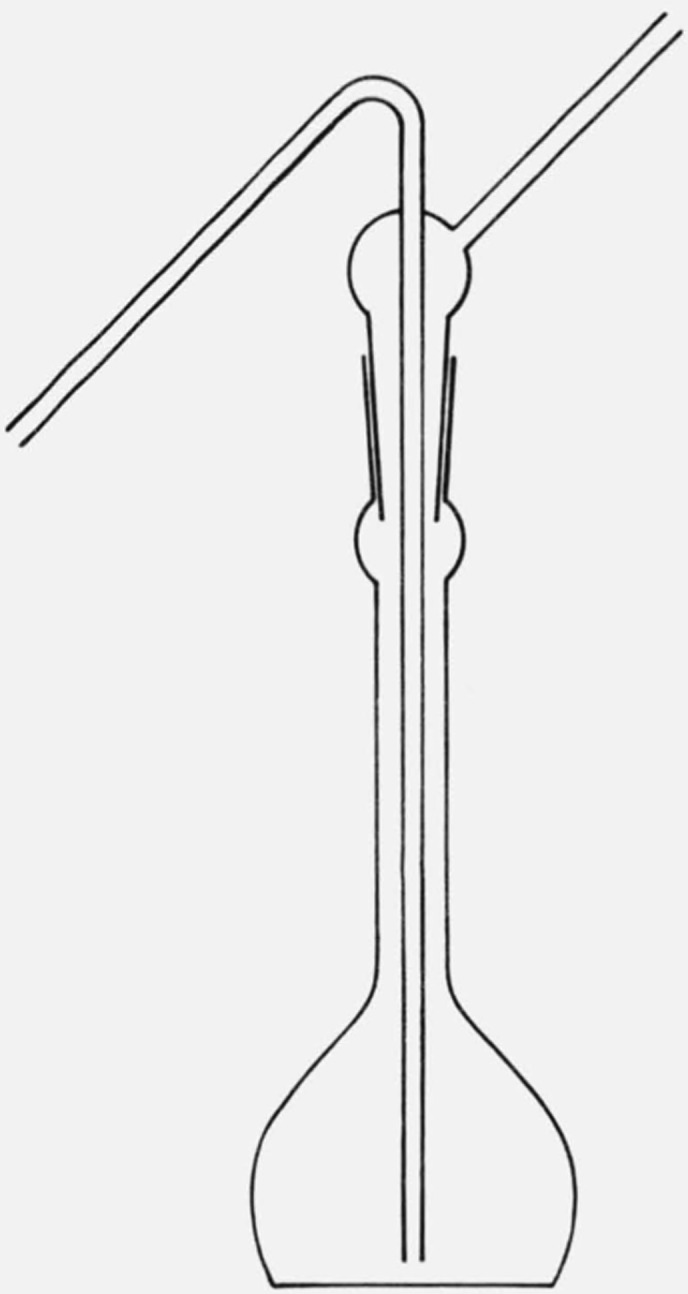
The solutions were transferred into the viscometer by a wash-bottle-like siphon (see fig. 1) which was found to be more convenient than a heated pipette. Due to the low thermal mass of the fine glass tubing, it was found unnecessary to preheat the siphon. The viscometer was rinsed twice with about 4 cm3 of the solution then about 10 cm3 was siphoned in for the flow time measurement. An automatic viscometer timer (Hewlett-Packard Model 5901B Autoviscometer3) was used to operate the viscometer and measure the flow times, while the viscometer was thermostatted in a Hewlett-Packard 5901A Constant Temperature Bath.3
Figure 1.

Solution transfer siphon.
Advantages of an automatic viscometer timer are that the same amount of liquid is automatically drawn up to each time and that the flow time is measured to 0.001 seconds. The former contributes to the uniformity of the measurement, the latter makes possible the use of very dilute solutions, which greatly facilitates reliable extrapolations to zero concentration. A third advantage is that the cleanliness of the viscometer can be judged by the reproducibility of the flow times. Ordinarily, flow times will fall in a range of 0.03 seconds or less. In the presence of lint or dust the flow time will drift or will be randomly erratic with a range of up to 0.2 seconds.
Kinetic energy corrections were made in all cases [8]. These amounted to about 1.2 percent for 1,2,4-trichlorobenzene solutions, and about 0.3 percent for the decalin and 1-chloronaphthalene solutions. The rate of shear in the Ubbelohde viscometer used was about 1000–1500 seconds−1. Measurements on a higher molecular-weight linear polyethylene fraction (Mn = 355,300, Mw = 688,000) at shear rates from 20 to 1500 s−1 reveal no dependence of measured viscosity number on shear rate. We therefore assume that the measured viscosity numbers of SRM 1475 exhibit no shear-rate dependence in this region.
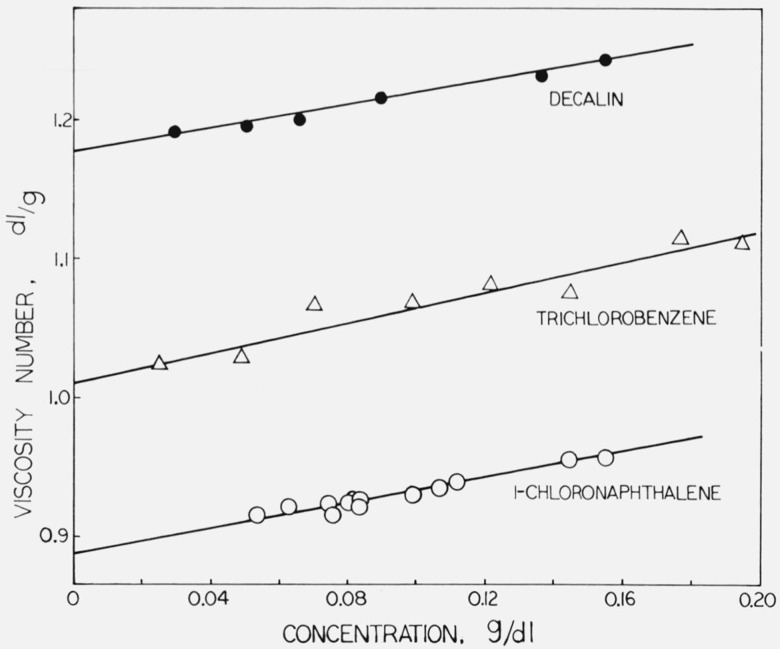
Since the flow time (corrected to allow for kinetic energy of the effluent from the capillary) in a Ubbelohde viscometer is proportional to solution viscosity, the viscosity number can be written (ts − t0)/(t0c), where c is concentration and ts and t0 are flow times for solution and solvent respectively. The standard deviation in the viscosity number of aliquots of the same solution was found to be slightly less than 0.3 percent. The viscosity numbers were fitted by least squares to linear functions of concentration; the limiting viscosity numbers were obtained as the resulting constant terms. The results are given in table 1. The viscosity numbers are plotted against concentration in figure 2, which also shows the straight lines obtained from the least-squares analysis.
Table 1.
| Solvent | Limiting viscosity number, dl/g | Slope of viscosity number versus concentration, (dl/g)2 |
|---|---|---|
| 1-chloronaphthalene 1,2,4-trichlorobenzene decahydronaphthaleneb |
a0.890 ± 0.0032 1.010 ± .0086 1.180 ± .0032 |
0.48 .55 .72 |
Uncertainties quoted are estimated standard deviations obtained from linear least squares fits of viscosity number versus concentration.
Technical grade, which assayed at approximately equal proportions of cis- and trans-decahydronaphthalenes.
Figure 2.
Limiting viscosity numbers of SRM 1475.
Considerable care must be exercised in making viscosity measurements when decalin is used as the solvent. Errors can easily arise due to the widely differing properties of the cis- and trans-isomers of decahydronaphthalene. The cis-isomer has a boiling point about 10 °C higher, a density about 3 percent greater, and a viscosity about 20 percent higher than the trans-isomer. If the solutions are made up by weight, density must be measured for each batch of solvent. Since the isomers differ in volatility, condensation in the upper part of the viscometer can change the isomeric composition in the solution. The resulting error in flow time can cause errors of 5 percent or more in the viscosity number. These errors were minimized in he present work by repeatedly equilibrating the viscometer with fresh portions of solvent. After reproducible solvent flow times were obtained, the flow times of the solutions were measured. We believe that by the use of these techniques, the errors due to the variable composition of decalin have been reduced to less than 1 percent.
Footnotes
Figures in brackets indicate the literature references at the end of this paper.
Available from the American Society for Testing and Materials, 1916 Race Street, Philadelphia, Pennsylvania 19103.
Certain commercial equipment, instruments, or materials are identified in this paper in order to adequately specify the experimental procedure. In no case does such identification imply recommendation or endorsement by the National Bureau of Standards, nor does it imply that the material or equipment identified is necessarily the best available for the purpose.
2. References
- [1].Wesslau H., Makromol. Chem. 20, 111 (1956). [Google Scholar]
- [2].Francis P., Cooke R. Jr., and Elliott J., J. Polymer Sci. 31, 453 (1958). [Google Scholar]
- [3].Kotera A., et al. , Rept. Progr. Polymer Phys. Japan 3, 58 (1960). [Google Scholar]
- [4].Chiang R., J. Polymer Sci. 36, 91 (1959). [Google Scholar]
- [5].Tung L., J. Polymer Sci. 36, 287 (1959). [Google Scholar]
- [6].de la Cuesta M., and Billmeyer F. Jr., J. Polymer Sci. A 1, 1721 (1963). [Google Scholar]
- [7].Hoeve C. A. J., Wagner H. L., and Verdier P. H., J. Res. Nat. Bur. Stand. (U.S.), 76A (Phys. and Chem.), No. 2, 137–140 (Mar-Apr 1972). Paper I of this series. [DOI] [PMC free article] [PubMed] [Google Scholar]
- [8].Allen P. W., Techniques of Polymer Characterization, p. 180 (Butterworths, London, 1959). [Google Scholar]


