Significance
Inflatable structures are flat and foldable when empty and both lightweight and stiff when pressurized and deployed. They are easy to manufacture by fusing 2 inextensible sheets together along a defined pattern of lines. However, the prediction of their deployed shape remains a mathematical challenge, which results from the coupling of geometrical constraints and the strongly nonlinear and asymmetric mechanical properties of their composing material: thin sheets are very stiff on extensional loads, while they easily shrink by buckling or wrinkling when compressed. We discuss the outline shape, local cross-section, and state of stress of any curvilinear open path. We provide a reverse model to design any desired curved 2-dimensional shape from initially flat tubes.
Keywords: tension field theory, wrinkling instability, programmable structures
Abstract
Inflatable structures offer a path for light deployable structures in medicine, architecture, and aerospace. In this study, we address the challenge of programming the shape of thin sheets of high-stretching modulus cut and sealed along their edges. Internal pressure induces the inflation of the structure into a deployed shape that maximizes its volume. We focus on the shape and nonlinear mechanics of inflated rings and more generally, of any sealed curvilinear path. We rationalize the stress state of the sheet and infer the counterintuitive increase of curvature observed on inflation. In addition to the change of curvature, wrinkles patterns are observed in the region under compression in agreement with our minimal model. We finally develop a simple numerical tool to solve the inverse problem of programming any 2-dimensional (2D) curve on inflation and illustrate the application potential by moving an object along an intricate target path with a simple pressure input.
A domain of application for pneumatic structures has emerged with the current development of soft robotics actuators (1). Unidirectional bending of elastomeric pneumatic structures can be easily controlled by internal pressure (2), and recently, more general complex shape morphing was achieved (3). As they rely on large material strains, these structures are based on elastomers and therefore, have a relatively low stiffness, which makes them unsuitable for large-scale structures and heavy loads. In contrast, stiff inflatables may be obtained by stitching flat pieces of thin but nearly inextensible material. As a first example, sky lanterns were invented during the 3rd century in China (4); then, they were rediscovered and scaled up by the Montgolfier brothers for ballooning in the 18th century. Since then, stiff inflatables have been widely used in engineering (5), medicine (6), architecture, and aerospace (7–9). Here, we show how to shape-program slender “flat-inflatable” structures, which are extremely easy to manufacture: 2 identical patches are cut in thin sheets and sealed along their boundaries (10). Common examples from everyday life are Mylar balloons. Although they are easy to manufacture, predicting the 3-dimensional shape of such flat-inflatable structures (i.e., maximizing a volume that a thin inextensible sheet can encompass) remains a challenge due to geometrical constraints. Indeed, changing the Gaussian curvature (i.e., the product of both principal curvatures of a surface) implies a distortion of the distances within the surface. In the case of thick elastic plates, local stretching or compression may accommodate changes in metrics. However, inextensible sheets behave nonlinearly: they can accommodate compression by forming wrinkles but cannot be stretched. Tension field theory, the minimal mathematical framework to address this problem, has been developed to predict the general shape of initially flat structures. While solutions have been found for axisymmetric convex surfaces (11–13) and polyhedral structures (14, 15), predictions in a general case remain an open issue and have been addressed numerically in the computer graphics community (16). In a seminal paper, Taylor (17) described the shape of an axisymmetric parachute with an unstretchable sail, a solution also appearing in recent studies on the wrapping of droplets with thin polymeric sheets (18–20).
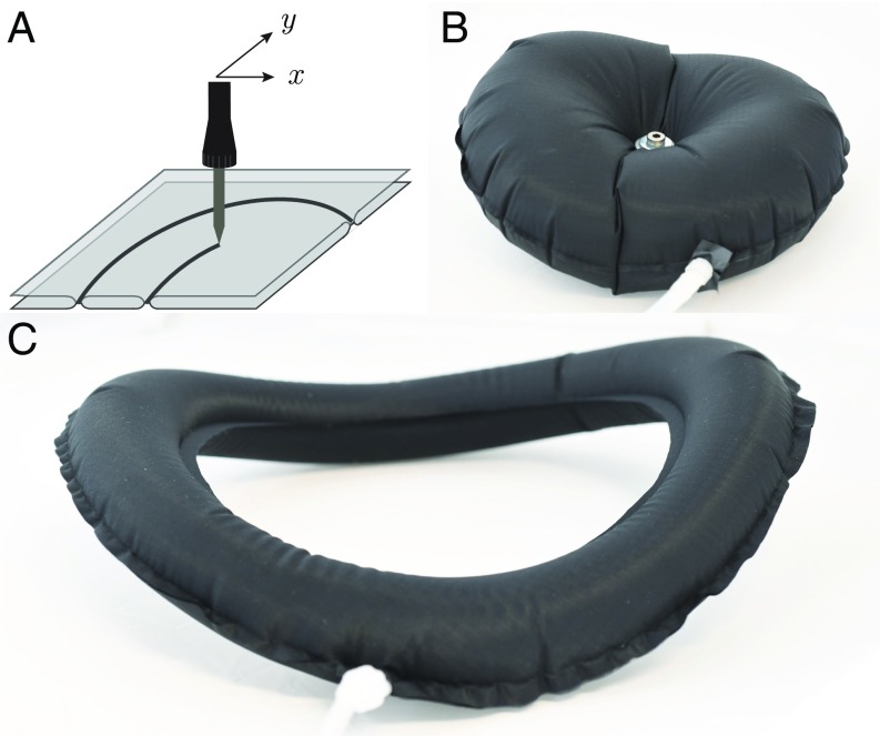
We study macroscopic structures made of thin quasiinextensible planar sheets heat sealed along a desired path using a soldering iron with controllable temperature mounted on the tracing head of a 2-directional plotter (10) (Materials and Methods and Fig. 1A). We focus on simple configurations where pairs of identical flat patches forming curvilinear paths of constant width are bonded along their edges. When inflating a straight ribbon, we trivially obtain, far from the extremities, a perfect cylinder of circular cross-section. In contrast, inflating a flat ring results into complex features. We observe, for instance, an out-of-plane instability in the case of closed paths and the presence of radial wrinkles and folds (Fig. 1 B and C). We show in this article that inflation induces an overcurvature of the outline through a detailed study of its cross-section. We first describe the cross-section of axisymmetric annuli. We then extend our analysis to open rings to predict the position of compressive zones and the change in intrinsic curvature. We finally devise an inverse method for programming the outline of any arbitrary inflated curved flat path and illustrate the strong workload capacity of these actuators by displacing an object along a complex path with a simple pressure input.
Fig. 1.
Flat sealed inflatables. (A) Heat sealing of 2 sheets together along a desired path using an soldering iron mounted on a 2-directional plotter. (B) Photograph of an experimental realization of inflating an annulus of inner radius and width , with . Wrinkles appear, and 2 diametrically opposed kinks are observed. (C) For , the inflated structure buckles smoothly out of plane. Both structures are made of thermoplastic polyurethane-coated nylon fabric.
Results and Discussion
Closed Rings.
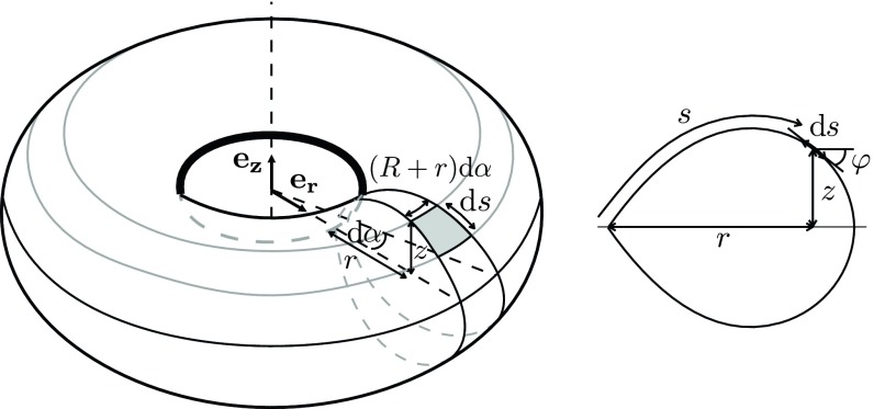
We first consider a swim ring configuration: a planar axisymmetric annulus of inner radius and width . We describe the cross-section of the inflated annulus in the plane as with the curvilinear abscissa (Fig. 2). We assume that the structure is in a doubly asymptotic regime: the sheet may be considered as inextensible (i.e., ) but can accommodate any compression by forming wrinkles or folds (21–24) (). The shape of the membrane may, therefore, be obtained by maximizing the enclosed volume (SI Appendix). Here, we choose to derive this shape by considering the balance of tension along the membrane path and applied pressure in the plane. Owing to inextensibility, the hoop direction conversely undergoes contraction, except along the inner perimeter of the torus. Indeed, all material points have a radial displacement component toward the axis of symmetry of the torus when inflated. Following the framework proposed by Taylor (17), we define a tension per unit length (defined in the inflated state as in Fig. 2 and SI Appendix, Fig. S1), and we consider the force balance along a surface element of extent on an angular section (Fig. 2). In the absence of forces in the compressed hoop direction, balancing the force in the tangent plane of the surface element reads . The tension thus reads , where is a constant to be determined. The tension along the curved membrane balances the pressure force acting normal to the surface element following Laplace law and reads
| [1] |
where is the slope of the cross-section with respect to . Using the geometrical relation , differentiating Eq. 1 shows that the shape of the section is the solution of the classical nonlinear oscillator ordinary differential equation for :
| [2] |
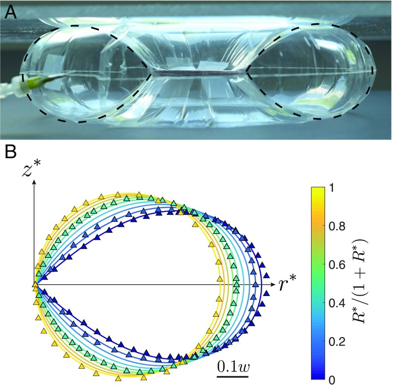
which must be complemented by boundary conditions. Symmetry with respect to the plane imposes , which leads to the boundary condition for Eq. 2. A second imposed condition is that the inner seam remains under tension, which leads to . The force balance normal to the surface of the sheet (Eq. 1) provides the corresponding condition for : . The absence of radial force at the outer seam imposes . A detailed justification of these boundary conditions and of Eqs. 1 and 2 may be found in SI Appendix using variational techniques. The equation is solved with standard shooting methods, which determines the constant . Using and , we translate the solution into the corresponding profile. Denoting dimensionless lengths with the subscript *, we display the dimensionless shapes vs. in Fig. 3B, solid lines and compare them with experimental profiles (triangles in Fig. 3B and image in Fig. 3A) for values of the aspect ratio ranging from 0.05 to 0.95. For slender geometries (i.e., ), the section of the torus is a circle as expected for a straight elongated balloon. For smaller values of , the section presents a singular wedge along the inner radius of the torus (Fig. 3 and SI Appendix). The agreement between calculated and measured profiles is remarkable without any adjustable parameter. The toroidal structure is, as predicted by the geometrical model, decorated with alternating wrinkles and crumples (21, 25) everywhere except at the inner edge of the structure (Fig. 3A and SI Appendix, Fig. S2). However, we observe that the global structure does not remain in plane on inflation and tends to buckle out of plane, exhibiting either diametrically opposed localized kinks for very thin sheets and or a regular oscillating shape for relatively thicker sheets, , and high-enough pressures (Fig. 1, SI Appendix, Fig. S2, and Movie S1).
Fig. 2.
Sketch of the inflated ring with the definition of the parameters and coordinates, where is the radial distance to the axis of symmetry, is the height, is the curvilinear coordinate along the membrane in the plane, and is the local slope of the profile.
Fig. 3.
Cross-section of a closed inflated annulus. (A) Profile picture of a closed inflated annulus, the axisymmetry of the structure being constrained by 2 plates to prevent out-of-plane buckling. The ring is made of a 16-m-thick polypropylene sheet of inner radius mm and outer radius mm. Dashed lines correspond to the theoretical cross-sections. Note that the wrinkles extend through the whole torus. (B) Theoretical (solid lines) and experimental (triangles) rescaled cross-sections of inflated closed rings for various aspect ratios with . and correspond the rescaled radial and vertical coordinates, respectively.
Coiling of Open Rings.
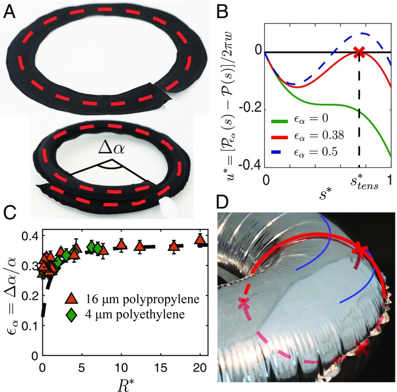
These observations suggest the existence of geometrical frustration in closed inflated rings, which is reminiscent of the buckling of rings with incompatible intrinsic curvature (26) or of the warping of curved folds (27). This constraint is readily assessed when a cut is performed on the annuli (and both ends are sealed), thus removing the closing condition. With this additional degree of freedom, the structures remain in plane, but the curvature of their outline increases, which results into an overlapping angle (Fig. 4A). Considering a cut in the plane, the pressure force acting on 1/2 of the ring is , where is the area of the 2 cross-sections. In the closed configurations, the membrane tension balancing this separating pressure force is entirely supported by the inner seam, all others points of the membrane being under hoop compression. On a single cross-section, the pressure force induces a residual torque with respect to the inner seam. For an open ring, having a free end and no external loading imposes a vanishing internal torque in any cross-section of the structure. The initially unbalanced pressure torque induces the curvature of the structure until 2 symmetric lines of tension appear and provide internal torque balance (Fig. 4D). Counterintuitively, pressurizing curved structures increases their curvature.
Fig. 4.
Overcurvature of an open torus. (A) A circular annulus cut and sealed (Upper) curves more on inflation (Lower) and exhibits an excess angle . (B) Dimensionless perimeter difference as a function of the curvilinear coordinate for various overcurvature strains in the case (circular section on inflation). in the flat state. (Green line) On inflation with . (Red line) For (the red cross indicates the abscissa under tension). (Dashed blue line) For (this solution is not physically relevant, since it implies azimuthal extension). (C) Experimental and theoretical (dashed line) target curvature change as a function of the ratio . Triangles indicate experiments with 16-m sheets of polypropylene; diamonds indicate experiments with 4-m sheets of polyethylene. (D) Wrinkles are absent along a band of finite width, which is highlighted in blue. The red line corresponds to the theoretically calculated profile (within the limit of inextensibility), and the red crosses mark the positions of the tensions lines for .
We show in SI Appendix that overcoiling is associated with an increase of the enclosed volume and assume that the optimal coiling is determined by the inextensibility condition. For a quantitative description, we consider an open annulus of inner radius and width in the flat configuration. The overlap results into a new inner radius , with the strain . We assume that, far from the ends of the open annuli, the family of profiles calculated for closed rings remains valid. However, the current shape profile corresponds to the new aspect ratio . The local projected perimeter of the structure at the curvilinear coordinate is thus equal to . Due to inextensibility condition, this perimeter is bounded by its initial value in the flat configuration . We represent in Fig. 4B the normalized difference
| [3] |
as a function of the nondimensional abscissa , imposing for the case of . As described previously, is always negative for : that is, all material points are under azimuthal compression except for the inner point (Fig. 4B). As is increased, the curve presents a secondary maximum, which increases. This maximum eventually reaches 0 at a position for a particular value (Fig. 4B). Beyond this point, is partly positive, which breaks the inextensibility condition. As the open structure is inflated, we thus expect to take the value , for which mechanical equilibrium is attained with 2 additional up-down symmetric lines of tension along the membrane. Although in Eq. 3, the profile depends, in principle, on , we assume here that this dependence remains modest.
If we approximate this profile as the closed axisymmetric profile before additional curving [that is, in Eq. 3], the position of the line under orthoradial tension can be readily determined. Searching for the condition when the maximum of vanishes leads to
| [4] |
As an illustration, this value can be directly computed in the limit , where the section is almost circular and the profile follows . Searching for the maximum of the function leads to the transcendental equation . The numerical solution gives and consequently, (i.e., ). The curvature varies accordingly from to .
In Fig. 4C, we compare the experimental measurement of conducted with polymer sheets with the theoretical predictions from Eq. 4 and find a very good agreement with experimental data for . The predicted position for the region under tension (red crosses in Fig. 4D) also matches the observed region free from wrinkles. Nevertheless, this region is actually not limited to a line but presents a finite width. We interpret this difference as a consequence of the finite stiffness of the sheet as described in a seminal paper by King et al. (21) in a simpler geometry and of the simplifying assumption that the profile of the structure is strictly similar to the axisymmetric closed configuration.
Inverse Problem.
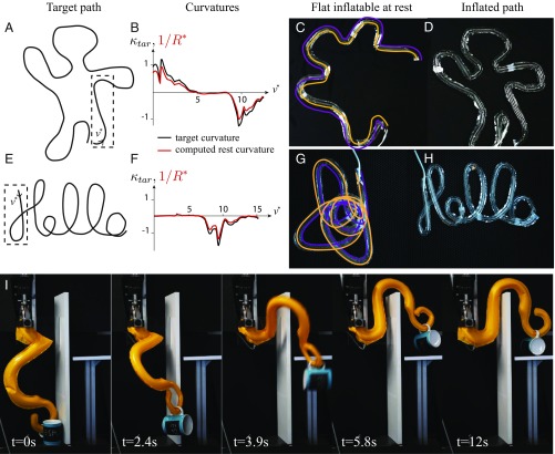
Having rationalized the change in curvature on inflation, we propose to use our geometrical model to inverse the problem (i.e., to determine the path of width leading to an inflated structure of an arbitrary desired 2D shape with free ends). For a given target curve (Fig. 5 A and E), we first numerically calculate the curvature , where denotes the curvilinear coordinate along the path to be programmed normalized by the width (Fig. 5 B and F). The same parametrization may be used in the flat state, since the inner edge does not stretch or contract on inflation, and the tube is chosen slender (). The normalized radius of curvature of the corresponding flat ribbon is then obtained by solving numerically the relationship
| [5] |
where was computed above and plotted in Fig. 4C (Fig. 5 B and F). This relationship is rigorously valid only in the case of slowly varying curvatures (; i.e., when the outline of the path may be locally seen as a path of constant curvature). The contours of the balloons are then plotted with the correct curvature (Fig. 5 C and G). If overlap occurs, as in the case of the “Hello” curve, the path is printed in several nonoverlapping distinct parts that are bonded together using tape. On inflation, we do obtain with great precision the target shape (Movies S3 and S4). Depending on the initial curves, the inflated structures may expand (Hello) or conversely, contract (waving man). The programming of a simpler and smoother shape, a lemniscate, is shown in SI Appendix, Fig. S4. This offers a path for a kind of strong lightweight actuators with programmable shapes. Harnessing geometrical nonlinearities, one can predict the complex deformation path to displace objects with mere pressure input. In Fig. 5I and Movie S5, the octopus-like arm lifts a mug weighing several times its own weight and carries it to a platform behind an obstacle. Large workload with particularly large stroke may thus be reached with a very simple object.
Fig. 5.
Inverse problem for getting any curved shape. (A and E) Target path. (B and F) Normalized target and rest curvature for a given path width , , and , as a function of the curvilinear coordinate . The portion of the target path plotted is highlighted in A by a dashed box. The curvature of the flat path is computed using the prediction for curvature change plotted in Fig. 4C, which is according to Eq. 4. (C and G) Flat path computed by the inverse model on top of a photograph of the experimental realization. (D and H) Same path under pressure fitting closely the target curve (Movies S3 and S4). (I) Manipulation of a mug. On inflation, the lightweight arm deforms along a predicted path within a few seconds, passing an obstacle to carry the mug on a platform (Movie S5).
Concluding Remarks.
In this report, we have shown that the physics and geometry of apparently mundane flat sealed inflatables, such as “Mylar balloons,” are far richer than expected: the shape of their section includes singularities and a nontrivial distribution of wrinkles; the outline of an inflated curved balloon with free ends overcurves under inflation. Commercially available Mylar balloon letters are empirically designed to compensate for this overcurvature. For example, the letter O has, before inflation, a missing angular sector and rather looks like a C (14) (SI Appendix, Fig. S3). Our model based on the assumption of perfectly inextensible and infinitely bendable membranes does capture quantitatively this coiling for aspect ratio as well as the shape of the cross-sections and the positions of wrinkles. In practical engineering systems, minor corrections due to the finite stiffness of the sheet should nevertheless be accounted for in the case of high pressure (28, 29). Another remaining challenge is to rationalize the mechanical properties of such structures: how does the complex stress pattern revealed by regular folds and wrinkles impact the bending stiffness of the inflated device (22–24)? Beyond this mechanical question, our study remarkably enriches the possibilities for simply manufactured 1-dimensional stiff deployable structures for which the inverse problem may be solved.
Materials and Methods
We fabricate the curved balloons by displaying 2 thin sheets made of the same thermosealable material (thermoplasticurethane-impregnated nylon fabric, Mylar, polypropylene) covered by a sheet of greaseproof paper in the working area of an XY plotter (from Makeblock). A soldering iron with controllable temperature (PU81 from Weller) is then mounted on the tracing head of the plotter (Fig. 1A). Using the dedicated software mDraw, we “print” the desired path designed with any vector graphics software. Playing with both temperature and displacement speed of the head, one can simply seal or additionally cut along the path. The envelopes obtained are then connected to the compressed air of the laboratory and inflated. The pressure is then set at typically 0.1 bar to ensure that we remain in the regime of interest (quasiinextensible, compression modulus negligible) for our structures with a width on the order of 10 cm, thickness of typically 10 m, and Young modulus of the order of the gigapascals. Cross-sections are measured by drawing a radial line on a transparent Mylar balloon; a photograph from the side is then taken, and the line is extracted.
Supplementary Material
Acknowledgments
This work was partially funded by the French Agence Nationale de Recherche (ANR), project SMART. We thank Corrado Maurini for enlightening discussions.
Footnotes
The authors declare no conflict of interest.
This article is a PNAS Direct Submission. T.A.W. is a guest editor invited by the Editorial Board.
This article contains supporting information online at www.pnas.org/lookup/suppl/doi:10.1073/pnas.1904544116/-/DCSupplemental.
References
- 1.Rus D., Tolley M. T., Design, fabrication and control of soft robots. Nature 521, 467–475 (2015). [DOI] [PubMed] [Google Scholar]
- 2.Shepherd R. F., et al. , Multigait soft robot. Proc. Natl. Acad. Sci. U.S.A. 108, 20400–20403 (2011). [DOI] [PMC free article] [PubMed] [Google Scholar]
- 3.Siéfert E., Reyssat E., Bico J., Roman B., Bio-inspired pneumatic shape-morphing elastomers. Nat. Mater. 18, 24–28 (2019). [DOI] [PubMed] [Google Scholar]
- 4.Deng X., Clefted Equilibrium Shapes of Superpressure Balloon Structures (California Institute of Technology, 2012). [Google Scholar]
- 5.Wielgosz C., Thomas J. C., Deflections of inflatable fabric panels at high pressure. Thin-Walled Struct. 40, 523–536 (2002). [Google Scholar]
- 6.Serruys P. W., et al. , A comparison of balloon-expandable-stent implantation with balloon angioplasty in patients with coronary artery disease. N. Engl. J. Med. 331, 489–495 (1994). [DOI] [PubMed] [Google Scholar]
- 7.Jenkins C. H., Gossamer Spacecraft: Membrane and Inflatable Structures Technology for Space Applications (American Institute of Aeronautics and Astronautics, 2001). [Google Scholar]
- 8.Pagitz M., The future of scientific ballooning. Philos. Trans. R. Soc. Lond. A 365, 3003–3017 (2007). [DOI] [PubMed] [Google Scholar]
- 9.Schenk M., Viquerat A., Seffen K., Guest S., Review of inflatable booms for deployable space structures: Packing and rigidization. J. Spacecr. Rockets 51, 762–778 (2014). [Google Scholar]
- 10.Ou J., et al. , “Heat-sealing inflatable shape-change materials for interaction design” in Proceedings of the 29th Annual Symposium on User Interface Software and Technology (Association for Computing Machinery, 2016), pp. 121–132. [Google Scholar]
- 11.Paulsen W., What is the shape of a mylar balloon? Am. Math. Monthly 101, 953–958 (1994). [Google Scholar]
- 12.Mladenov I., Oprea J., The mylar balloon revisited. Am. Math. Monthly 110, 761–784 (2003). [Google Scholar]
- 13.Ligaro S., Barsotti R., Equilibrium shapes of inflated inextensible membranes. Int. J. Sol. Struct. 45, 5584–5598 (2008). [Google Scholar]
- 14.Pak I., Inflating polyhedral surfaces. https://www.math.ucla.edu/∼pak/papers/pillow4.pdf. Accessed 2 August 2019.
- 15.Pak I., Schlenker J. M., Profiles of inflated surfaces. J. Nonlinear Math. Phys. 17, 145–157 (2010). [Google Scholar]
- 16.Skouras M., et al. , Designing inflatable structures. ACM Trans. Graph. 33, 63:1–63:10 (2014). [Google Scholar]
- 17.Taylor G. I., “On the shapes of parachutes” in Aerodynamics and the Mechanics of Projectiles and Explosions, Batchelor G. K., Ed (The Scientific Papers of Sir Geoffrey Ingram Taylor, Cambridge University Press, 1963), vol. 3, pp. 26–37. [Google Scholar]
- 18.Paulsen J., et al. , Optimal wrapping of liquid droplets with ultrathin sheets. Nat. Mater. 14, 1206–1209 (2015). [DOI] [PubMed] [Google Scholar]
- 19.Kumar D., Paulsen J. D., Russell T. P., Menon N., Wrapping with a splash: High-speed encapsulation with ultrathin sheets. Science 359, 775–778 (2018). [DOI] [PubMed] [Google Scholar]
- 20.Paulsen J. D., Wrapping liquids, solids, and gases in thin sheets. Annu. Rev. Condens. Matter Phys. 10, 431–450 (2019). [Google Scholar]
- 21.King H., Schroll R. D., Davidovitch B., Menon N., Elastic sheet on a liquid drop reveals wrinkling and crumpling as distinct symmetry-breaking instabilities. Proc. Natl. Acad. Sci. U.S.A. 109, 9716–9720 (2012). [DOI] [PMC free article] [PubMed] [Google Scholar]
- 22.Vandeparre H., et al. , Wrinkling hierarchy in constrained thin sheets from suspended graphene to curtains. Phys. Rev. Lett. 106, 224301 (2011). [DOI] [PubMed] [Google Scholar]
- 23.Vella D., Ebrahimi H., Vaziri A., Davidovitch B., Wrinkling reveals a new isometry of pressurized elastic shells. Europhys. Lett. 112, 24007 (2015). [Google Scholar]
- 24.Géminard J. C., Bernal R., Melo F., Wrinkle formations in axi-symmetrically stretched membranes. Eur. Phys. J. E 15, 117–126 (2004). [DOI] [PubMed] [Google Scholar]
- 25.Paulsen J. D., et al. , Geometry-driven folding of a floating annular sheet. Phys. Rev. Lett. 118, 048004 (2017). [DOI] [PubMed] [Google Scholar]
- 26.Moulton D., Lessinnes T., Goriely A., Morphoelastic rods. Part I. A single growing elastic rod. J. Mech. Phys. Sol. 61, 398–427 (2013). [Google Scholar]
- 27.Dias M., Dudte L., Mahadevan L., Santangelo C., Geometric mechanics of curved crease origami. Phys. Rev. Lett. 109, 114301 (2012). [DOI] [PubMed] [Google Scholar]
- 28.Roychowdhury S., DasGupta A., Inflating a flat toroidal membrane. Int. J. Sol. Struct. 67, 182–191 (2015). [Google Scholar]
- 29.Roychowdhury S., DasGupta A., Symmetry breaking during inflation of a toroidal membrane. J. Mech. Phys. Sol. 121, 328–340 (2018). [Google Scholar]
Associated Data
This section collects any data citations, data availability statements, or supplementary materials included in this article.


