

Abstract

With the rapid depletion of high-yield copper mineral resources and the accumulation of secondary copper resources, the recycling of secondary copper is gaining popularity in the copper industry. A copper anode furnace, often used in copper recycling, usually relies on methane combustion to melt copper scraps. In this work, a computational fluid dynamics (CFD) model of pure oxy-methane combustion is established to investigate the combustion characteristics of the CH4/O2 combustor in the copper anode furnace. The model is validated by comparing the simulation results with experimental measurements. The effects on flame length and temperature distribution are investigated under various fuel velocities, oxidizer velocities, and oxidizer temperatures. The results indicate that flame length and temperature distribution increase as the fuel velocity and oxidizer temperature increase, and decrease with the increase in oxidizer velocity. The flame length and temperature distribution always show an increasing trend with the increasing equivalence ratio. Based on the recycling capacity of the copper anode furnace, this validated CFD model can be used to optimize the operation parameters for controlling flame length and temperature distribution.
1. Introduction
With the rapid depletion of high-yield mineral resources, secondary copper resources have become an important materials supply for copper smelting industries. There are several types of equipment for recycling secondary copper in the copper industry: Kaldo furnace, tilting furnace, rotary anode furnace, and stationary reverberatory furnace.1−3 In each equipment, the main recycling processes are the melting process and refining process. The conventional melting process relies on fossil fuel combustion, using heavy oil or natural gas as the fuel and air as the oxidizer. However, it is inevitable to generate nitric oxides (NOx), which are some of the main air pollutants when using air or oxygen-enriched air as the oxidizer.
Oxy-fuel combustion technology is gradually gaining popularity in the industrial production of copper, aluminum, iron, and steel because of its inherent advantages. Compared with the conventional combustion, oxy-fuel combustion has higher combustion efficiency, lower volumes of exhaust gas, lower fuel consumption, higher melting capacity, and lower NOx emission.4 Especially when using pure oxygen combustion, NOx emission can theoretically be avoided altogether. In addition, compared with pulverized coal, kerosene, and heavy oil, methane is widely used as the industrial fuel for its clean and high calorific value advantages. Because of the aforementioned relative advantages, related studies5−8 of oxy-methane combustion have been reported to promote a wide range of industrial applications of this technology. For example, Dam et al.5 investigated the flame stability of CH4/O2 combustion experimentally and found that the stability regime of all compositions decreases as the burner diameter increases. Ditaranto et al.6 studied the coaxial CH4/O2 flame structure, and the results showed that the decrease in annular jet momentum leads to better turbulent mixing and, therefore, reduces the flame length. Li et al.7 carried out the experimental investigations of oxy-combustion in a laboratory-scale furnace and found that the furnace temperature rises slightly as the equivalence ratio increases. Shakeel et al.8 simulated the CH4/O2 combustion under various reaction mechanisms and found that the combinations of Jones–Lindstedt reaction mechanism and weighted sum of gray gas model (WSGGM) model gave the closest approximation to the experimental temperature profile.
The copper anode furnace is a common equipment for refining blister copper to anode copper in the copper industry.9,10 The furnace is a rotatable cylindrical furnace, which equips a CH4/O2 combustor on the end wall to provide heat to keep warm and melt solid materials. Because of the high-grade copper content in secondary copper, it is a feasible method to remelt and refine secondary copper in the anode furnace for copper recovery.2,11 However, there have been relatively few investigations of oxy-fuel combustion characteristics in the copper anode furnace. During the melting process of secondary copper resources in the copper anode furnace, the most important technological parameters that need to be controlled are flame length and temperature distribution. There should be an optimum value for the flame length to make sure that the temperature is distributed uniformly in the furnace and, on the other hand, the flame does not contact the melt directly to prevent the melt peroxidation. Kim et al.12 measured the flame lengths of turbulent oxy-fuel flames by using the visual determination method under a wide range of fuel nozzle diameters and oxidizer velocities. On this basis, Mei et al.13,14 defined a chemical flame length by carbon monoxide ratio at RCO = XCO/XCOmax = 0.01 for methane combustion, and the results indicated that this definition is more accurate than the other methods, such as those defined by RO = 0.09, yCO/yCO2 = 0.002, and so on.15−21
In order to investigate the effects of various velocities of fuel and oxidizer on flame length and temperature distribution, the definition of RCO = 0.01 will be adopted for measuring the flame length of the specific CH4/O2 combustor in this work. Moreover, the waste heat generated in the copper smelting industry can be utilized for reheating gases. To improve energy efficiency of the CH4/O2 combustor, the effects of various oxygen temperatures are also investigated. The aim of this work is to investigate the combustion characteristics of the CH4/O2 combustor, especially the effects of fuel velocities, oxidizer velocities, and oxidizer temperatures on flame length and temperature distribution, to provide guidance for optimizing the operating parameters in the secondary copper resources recovery process.
2. Results and Discussion
2.1. Mesh Independence Study
In order to avoid the potential error caused by the mesh, three different mesh levels, coarse mesh (69 000 cells), medium mesh (135 000 cells), and fine mesh (210 000 cells), were used to check the mesh independence. The mole fractions of CO and H2 along the X axis are plotted in Figure 1 under three different mesh levels. As shown in Figure 1, the coarse mesh cannot reflect the mole fractions of CO and H2 correctly, whereas after improving the mesh number to medium level and fine level, the variation between the medium mesh and the fine mesh is less than 1%. For the purpose of saving computing time and resources, the medium mesh was adopted in this simulation.
Figure 1.

Comparisons of the mole fractions of CO (a) and H2 (b) obtained under three mesh levels.
2.2. Effects of Various Fuel Velocities
With the development of large-scale production and large-scale equipment in the copper industry, energy consumption increases dramatically. Accordingly, the injection speed of natural gas is increased as the consumption of natural gas increases. Hence, it is necessary to investigate the changes of flame length and temperature distribution at various fuel velocities in the furnace. The oxygen velocity is set as a constant, and the detailed parameters used in the model are described in Table 1.
Table 1. Parameters Used in the CFD Model.
| case | fuel velocity (m/s) | TCH4(K) | oxidizer velocity (m/s) | TO2(K) | equivalence ratio |
|---|---|---|---|---|---|
| 1 | 30 | 300 | 100 | 300 | 0.72 |
| 2 | 40 | 300 | 100 | 300 | 0.96 |
| 3 | 50 | 300 | 100 | 300 | 1.20 |
| 4 | 60 | 300 | 100 | 300 | 1.44 |
| 5 | 70 | 300 | 100 | 300 | 1.69 |
| 6 | 80 | 300 | 100 | 300 | 1.93 |
| 7 | 90 | 300 | 100 | 300 | 2.17 |
| 8 | 100 | 300 | 100 | 300 | 2.41 |
According to Figure 2a, both the flame length and equivalence ratio increase as fuel velocity increases. Because the equivalence ratio is proportional to the fuel velocity, the flame length increases with the increasing equivalence ratio. As is well-known, fuel is excess when the equivalence ratio is greater than 1, whereas oxidizer is excess, when the equivalence ratio is less than 1. The combustion would theoretically achieve completion, when the equivalence ratio equals 1. In the simulation, combustion transforms from oxygen-enriched to methane-enriched as the equivalence ratio increases from 0.72 to 2.41. It can be seen from Figure 3 that the maximal mole fractions of CO, H2, and H2O along the X axis reduce obviously as fuel velocity increases except for CO2. As discussed in the refs,14,17 almost all CO2 is converted directly from CO in CH4/O2 combustion. Hence, the changing trend of maximal mole fraction of CO is dependent on the extent of the combustion reactions because CO is an intermediate chemical product. Because of the reduction of equivalence ratio, methane combustion transforms from complete combustion to incomplete combustion which results in a gradual decrease in maximal mole fraction of CO. For the same reason, the maximal mole fraction of H2 decreases as fuel velocity increases.
Figure 2.

Flame length and equivalence ratio (a), turbulence kinetic energy (b), and turbulent dissipation rate (c) profiles at various fuel velocities.
Figure 3.

Mole fractions of CO (a), H2 (b), CO2 (c), and H2O (d) along the X axis at various fuel velocities.
Moreover, Figure 2b,c report the turbulence kinetic energy and turbulent dissipation rate increase with the increasing fuel velocity and have gradually increasing distribution zones along the X axis. The mass flow rate of fuel increases with an increase in fuel velocity at a constant oxidizer concentration. These results imply that the increase in fuel velocity enhances the turbulent mixing, which results in an increase in the turbulent dissipation rate. Although the improvement in turbulent mixing can accelerate the combustion reactions to lead to rapid CO oxidation, the increasing fuel velocity plays a more significant role in fuel diffusion, which expands the combustion zone in the furnace. It is the reason that the distributions of mole fractions of CO, H2, CO2, and H2O along the X axis show increasing tendencies with the increase in fuel velocity in Figure 3. Similar to the results obtained by Tang et al.,22 the increase in fuel velocity leads to an increasing tendency in flame length and temperature distribution shown in Figures 2a and 4. Moreover, a similar phenomenon was observed in Xi’s experiments,23 which investigated the effect of fuel mass flow rate on flame length. They attributed the increase in flame length to the enhancement of fuel axial and radial diffusion, which is in accordance with the increasing trend of turbulence kinetic energy as shown in Figure 2.
Figure 4.

Temperature distribution at various fuel velocities; the unit of length is m.
It can be concluded that with the increase in the turbulence kinetic energy, the turbulent mixing of fuel and oxidizer is enhanced, which leads to an expansion of the combustion zone in the furnace. The transportation of species and energy transfer show great improvement as well and increase the flame length and temperature distribution. As a result, fuel velocity plays a significant role in flame length and temperature distribution. However, the optimal fuel velocity should be selected according to the capacity of the copper anode furnace to avoid wasting fuel resources.
2.3. Effects of Various Oxidizer Velocities
To investigate the effects of various oxidizer velocities on flame length and temperature distribution, the fuel velocity is set as a constant and the detailed parameters of various oxidizer velocities are shown in Table 2. The results are shown below.
Table 2. Parameters of Various Oxidizer Velocities Used in the CFD Model.
| case | fuel velocity (m/s) | TCH4 (K) | oxidizer velocity (m/s) | TO2 (K) | equivalence ratio |
|---|---|---|---|---|---|
| 1 | 40 | 300 | 70 | 300 | 1.38 |
| 2 | 40 | 300 | 80 | 300 | 1.20 |
| 3 | 40 | 300 | 90 | 300 | 1.07 |
| 4 | 40 | 300 | 95 | 300 | 1.01 |
| 5 | 40 | 300 | 100 | 300 | 0.96 |
| 6 | 40 | 300 | 105 | 300 | 0.92 |
As shown in Figure 5a, the flame length and the equivalence ratio decrease gradually with the increase in oxidizer velocity. Because of the equivalence ratio exhibiting a negative linear relationship with oxidizer velocity, the flame length shows a similar increasing trend with the increasing of equivalence ratio, which is consistent with Figure 2a. Figure 5b,c depict the increase in turbulence kinetic energy and turbulent dissipation rate with the increase in oxidizer velocity. However, compared with Figure 2b, the difference in Figure 5b is that the distribution of turbulence kinetic energy along the X axis has almost the same area under various oxidizer velocities. It implies that the increase in oxidizer velocity plays a smaller role in turbulence diffusion than the effect of fuel velocity.
Figure 5.

Flame length and equivalence ratio (a), turbulence kinetic ratio (b), and turbulent dissipation rate (c) profiles at various oxidizer velocities.
According to Figure 6, the distributions of mole fractions of CO, H2, CO2, and H2O have decreasing trends along the X axis as the oxidizer velocity increases. Moreover, the maximal mole fractions of CO, H2, and H2O increase with the increase in oxidizer velocity. Considering the changing trend of equivalence ratio, the combustion transforms from oxidizer lean to fuel lean as the oxidizer velocity increases. The extent of combustion reactions are improved gradually with the increasing oxidizer velocity, which lead to an increase in the maximal mole fraction of CO. The turbulent mixing is enhanced with the increase in oxidizer velocity, so CO oxidation is speeded up, which shortens the distributions of CO and CO2 mole fractions along the X axis. These results are found to be in good agreement with the measurements from Degenève et al.,24 who reported a reduction in the potential core length of the central jet with the increasing annular momentum ratio.
Figure 6.

Mole fractions of CO (a), H2 (b), CO2 (c), and H2O (d) along the X axis profiles at various oxidizer velocities.
Figure 7 reports that the temperature distribution in the furnace shows a decreasing tendency with the increase in oxidizer velocity. Different from the effect of the inner core fuel stream, the outer annular oxidizer stream constitutes the envelope of the flame and has little influence on the internal species transport and energy transfer along the X axis. Theoretically, with the decrease in equivalence ratio from 1.38 to 0.92, the total heat released by the combustion reactions would tend to increase. However, with the oxidizer velocity increasing, the excess mass flow rate of the oxidizer gas increases and takes away more heat. Therefore, under a constant fuel velocity, there should be an optimal oxidizer velocity to realize the most efficient use of heat in the furnace.
Figure 7.

Temperature distribution at various oxidizer velocities, length unit is m.
2.4. Effects of Various Oxidizer Temperature
In order to meet the target of improving energy resource utilization and reducing products cost, waste heat generated in the copper industry can be used to preheat the oxidizer gas. Because a change in temperature can affect gas density, turbulence viscosity, and turbulence kinetic energy, and then affect the combustion characteristics,25 it is necessary to investigate the change trends of flame length and temperature distribution at various oxidizer temperatures. The detailed parameters used in the computational fluid dynamics (CFD) model are shown in Table 3, and the results are shown below.
Table 3. Parameters of Various Oxidizer Temperature Used in the CFD Model.
| case | fuel velocity (m/s) | TCH4 (K) | oxidizer velocity (m/s) | TO2 (K) | equivalence ratio |
|---|---|---|---|---|---|
| 1 | 40 | 300 | 100 | 300 | 0.96 |
| 2 | 40 | 300 | 100 | 375 | 1.21 |
| 3 | 40 | 300 | 100 | 575 | 1.85 |
| 4 | 40 | 300 | 100 | 775 | 2.50 |
| 5 | 40 | 300 | 100 | 975 | 3.14 |
| 6 | 40 | 300 | 100 | 1175 | 3.78 |
As shown in Figure 8a,b, the flame length increases with the increase in oxidizer temperature, while the turbulence kinetic energy and the distribution of turbulence kinetic energy along the X axis decrease. Figure 8c depicts the decreasing trends of turbulent dissipation rate and the distribution along the X axis with the increase in oxidizer temperature. As analyzed in Tang et al.’s work,25 the increasing oxidizer temperature reduces the turbulence viscosity which results in a reduction in gas entrainment and an increase in flame length. The reducing turbulence viscosity leads to a decrease in the turbulent dissipation rate, which is consistent with Figure 8c. In addition, as gas density will decrease with the increase in oxidizer temperature, the mass flow rate of oxidizer gas decreases gradually at a constant inlet velocity, which results in a decrease in the total kinetic energy carried into the furnace. As a consequence, reducing the oxidizer gas mass flow rate results in an increase in the equivalence ratio but a decrease in turbulence kinetic energy. It is interesting to note that the flame length shows an increasing trend with the increase in the equivalence ratio, which is in good agreement with the effects of fuel velocity and oxidizer velocity.
Figure 8.

Flame length and equivalence ratio (a), turbulence kinetic energy (b), and turbulent dissipation rate (c) profiles along the X axis at various oxidizer temperatures.
Figure 9 reports that the maximal mole fractions of CO, H2, and H2O decrease as the oxidizer temperature increases, whereas the distributions increase along the X axis. This phenomenon can be explained by the same reason mentioned previously that as the equivalence ratio increases, the combustion transforms from fuel lean to oxidizer lean and the extent of combustion reactions is suppressed gradually. As CO and H2 are intermediate products, their maximal mole fractions are dependent on the extent of combustion reactions and therefore show a decreasing tendency. The increase in turbulence kinetic energy can enhance the turbulence mixing and accelerate the combustion reaction rates to result in more rapid oxidation of CO and H2 at a shorter distance. This is why the distributions of mole fractions of CO, H2, CO2, and H2O show increasing trends along the X axis with the increase in oxidizer temperature.
Figure 9.

Mole fractions of CO (a), H2 (b), CO2 (c), and H2O (d) along the X axis at various oxidizer temperatures.
As shown in Figure 10, the temperature distribution tends to increase with the increase in oxidizer temperature. Actually, the total heat released by combustion decreases with the increasing equivalence ratio at a constant fuel input. However, the temperature distribution is getting more and more uniform in the furnace with the increasing oxidizer temperature. It means raising oxidizer gas temperature can not only increase energy efficiency but also improve the uniformity of temperature distribution.
Figure 10.

Temperature distribution at various oxidizer temperatures.
3. Conclusions
In the present work, the combustion characteristics of the CH4/O2 combustor in a copper anode furnace have been investigated by numerical simulation. The effects of various fuel velocities, oxidizer velocities, and oxidizer temperatures on flame length and temperature distribution were studied. Several conclusions can be drawn:
-
(1)
Both flame length and temperature distribution in the furnace increase with the increase in fuel velocity, whereas the maximal mole fractions of CO, H2, CO2, and H2O show decreasing tendencies. Compared with the effect on turbulent mixing, the increasing fuel velocity plays a more significant role in fuel diffusion and expands the combustion zone in the furnace.
-
(2)
The flame length and temperature distribution show decreasing trends with the increase in oxidizer velocity at a constant fuel velocity, whereas the maximal mole fractions of CO, H2, CO2, and H2O increase. Different from the effect of inner core fuel stream, the increase in oxidizer velocity has a greater influence on the turbulent mixing and speeds up the oxidation of CO.
-
(3)
The flame length and temperature distribution increase as the oxidizer temperature increases. The increase in temperature results in the reduction of turbulent viscosity and gas density. The reduction in turbulent viscosity leads to a decrease in gas entrainment which increases the flame length. However, the reduced gas density leads to a decrease in gas mass flow rate, which increases the maximal mole fractions of CO, H2, CO2, and H2O. The increasing oxidizer temperature can not only increase energy efficiency, but also improve the uniformity of temperature distribution.
4. Experimental Section
4.1. Geometry Model
Considering the research objective of the CH4/O2 combustor of the copper anode furnace, the interaction between the flame and copper melt during the melting process is ignored in the CFD model. The CH4/O2 combustor is a coaxial double tube construction, as shown in Figure 11a, of which the outer tube is for pure oxygen and the inner tube is for natural gas. The geometry of the model is shown in Figure 11b, and an axisymmetric computational domain was applied in the model to reduce computational time and effort.
Figure 11.
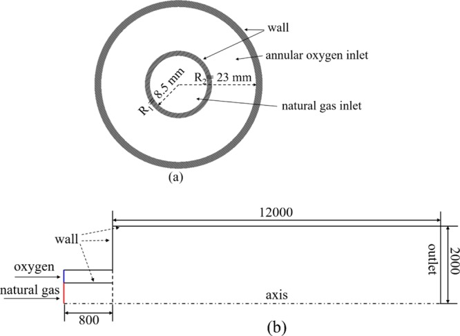
Structure of CH4/O2 combustor (a) and the sketch of geometric model (b), length unit is mm.
4.2. Numerical Model
In this work, a CFD model was developed to investigate the combustion characteristics of the CH4/O2 combustor in the copper anode furnace. The chemical flame length in the numerical model is obtained by the definition of carbon monoxide ratio as RCO = XCO/XCOmax = 0.01, where XCO is the local mole fraction of carbon monoxide and XCOmax is the maximum mole fraction of carbon monoxide of the combustion components. According to the refined 4-step global mechanism26 of methane combustion described in Table 4, carbon monoxide is regarded as the last intermediate product and the ratio of RCO = 0.01 can approximately represent the border of the reaction zone. In the simulation model, a contour of RCO = 0.01 is used as the reaction zone border and the flame length is the horizontal distance measured from the outlet of the combustor to the right endpoint of the border as depicted in Figure 12.
Table 4. The Refined 4-Step Global Mechanism of Methane Combustion26.
| no. | reactions | rate equations [kmol/(m3 T s)] | A | b | E |
|---|---|---|---|---|---|
| 1 | CH4 + 0.5O2 → CO + 2H2 | d[CH4]/dt = ATbe–E/(RT)·[CH4]0.5[O2]1.25 | 4.4 × 10¹¹ | 0 | 1.26 × 10⁸ |
| 2 | CH4 + H2O → CO + 3H2 | d[CH4]/dt = ATbe–E/(RT)·[CH4][H2O] | 3.0 × 10⁸ | 0 | 1.26 × 10⁸ |
| 3 | H2 + 0.5O2 ↔ H2O | d[H2]/dt = ATbe–E/(RT)·[H2][O2]0.5 (forward) | 5.69 × 10¹¹ | 0 | 1.465 × 10⁸ |
| 4 | CO + H2O ↔ CO2 + H2 | d[CO]/dt = ATbe–E/(RT)·[CO][H2O] (forward) | 2.75 × 10⁹ | 0 | 8.36 × 10⁷ |
Figure 12.

Definition of chemical flame length in the model
The governing equations were solved using the commercial software ANSYS 18.1. The Reynolds number of the fuel larger than 62 673 (Vfuel = 30 m/s) indicates that the flow is a turbulent flow in the CFD model. To simulate the turbulence behavior of the flow, the modified standard k–ε turbulence model with the standard wall functions was used as the turbulent model.27 For the species transport model, the eddy dissipation concept (EDC) model28 with a refined 4-step global mechanism26 was used to solve the species conservation and transportation. The discrete ordinate radiation model was employed with WSGGM29 as well in the present work.
4.3. Governing Equations
Mass conservation equation
| 1 |
Momentum conservation equation
| 2 |
where t̿ is the viscous stress tensor, given by
| 3 |
Energy equation
| 4 |
where keff is the effective conductivity, given by
| 5 |
Species conservation equation
| 6 |
where J⃗i is the diffusion flux term of species i, given by
| 7 |
where Di,m is the diffusion coefficient for species i in the mixture, and DT,i is the thermal diffusion coefficient.
4.4. Turbulence Model
The turbulence kinetic energy, k, and its rate of dissipation, ε, are obtained from the following transport equations
| 8 |
| 9 |
where Gk and Gb is the generation of turbulence kinetic energy due to the mean velocity gradient and buoyancy, respectively. YM represents the contribution of the fluctuating dilatation in compressible turbulence to the overall dissipation rate. C1ε, C2ε, and C3ε are constants.
Generally speaking, the standard k–ε turbulence model can be used for a wide range of turbulent flows for its economy and reasonable accuracy advantages. However, the standard k–ε turbulence model has a limit in the accuracy when the flow is located in a limited zone in which the effect of molecular viscosity would play an important role and cannot be ignored. Christo and Dally.27 and Frassoldati et al.30 investigated the effects of four different turbulence models (the modified k–ε turbulence model, standard k–ε turbulence model, renormalization group k–ε model, and realizable k–ε model), and they found that the modified k–ε turbulence model has more significant accuracy than the other three turbulence models. As adopted in the reference for simulating methane combustion,31−33 the modified k–ε standard model was used in the present work and the coefficient C1ε of the standard k–ε turbulence model is modified from 1.44 to 1.6.
4.5. Solution Method
In this work, the commercial software ANSYS Fluent 18.1 was used to simulate the oxy-fuel combustion process. The pressure-based solver was used to adjust the pressure and velocities after each iteration when solving the gas continuity and momentum equations. The finite volume method was used to solve the partial differential equations by discretizing the equations using an upwind differencing scheme over the finite volumes. The pseudo-transient option was set to improve the stability and convergence during the calculation.
The detailed boundary conditions in this simulation can be described as: the velocity inlet boundary conditions are employed for the annular oxygen inlet and natural gas inlet. The pressure outlet boundary condition is employed for the outlet and the gauge pressure is set to 0 Pa. The wall surface adopts the nonslip boundary condition and the near wall area adopts the standard wall surface function. The wall temperature and internal emissivity are fixed as 453 K and 0.9, respectively.
5. Validation
The same geometry described in ref (14) was used to validate the feasibility of the numerical model mentioned above. The flame lengths obtained in this simulation were compared with the flame lengths obtained in ref (14) by CFD modeling and obtained in ref (12) through experimental means. The comparison diagram is shown in Figure 13.
Figure 13.

Comparison diagram of flame lengths under various fuel velocity.
As shown in Figure 13, the results of the CFD model have good agreement with the results of ref (14) and the average error is less than 5%. The flame lengths of the numerical model have nearly identical changing trend compared with the experimental results obtained by Kim et al.12 This suggests that the numerical model may be suitable for the CH4/O2 combustor in this work.
Acknowledgments
The authors would like to thank the National Natural Science Foundation of China (grant number 51620105013) and the Fundamental Research Funds of the Central Universities of Central South University (grant number 1053320170390) for funding this work. The Center for Innovation through Visualization and Simulation (CIVS) at the Purdue University Northwest is also gratefully acknowledged for providing all the resources required for this work.
Glossary
Nomenclature
- XCO
mole fraction of carbon monoxide
- yCO
yield ratio of carbon monoxide
- yCO2
yield ratio of carbon dioxide
- Vfuel
fuel velocity, m/s
- ρ
density, kg/m3
- v⃗
fluid velocity, m/s
- p
static pressure, Pascal
- t̿
stress tensor
- g⃗
gravity, m/s2
- F⃗
external force
- μ
molecular viscosity, kg/m·s
- I
unit tensor
- ui
instant turbulence velocity on the direction xi, m/s
- E
total energy
- keff
effective conductivity, w/m·K
- T
local temperature, K
- hj
sensible enthalpy of species j
- J⃗i
diffusion flux term of species i
- Sh
heat of chemical reaction, and any other volumetric heat
- cp
temperature-dependent constant pressure specific heat
- μt
turbulent viscosity, kg/m·s
- Prt
turbulent Prandtl number
- k
turbulent kinetic energy, m2/s2
- Yi
local mass fraction of each species
- Ri
net rate of production of species i
- Di,m
diffusion coefficient for species i
- Sct
turbulent Schmidt number
- DT,i
thermal diffusion coefficient
- ε
turbulence dissipation rate, m2/s3
- σε
turbulent Prandtl number for ε, 1.3
- σk
turbulent Prandtl number for k, 1.0
The authors declare no competing financial interest.
References
- Samuelsson C.; Björkman B.. Copper recycling. In Handbook of recycling, 1st ed.; Worrell E., Reuter M. A., Eds.; Academic Press: Elsevier, 2014; pp 85–94. [Google Scholar]
- Wood J.; Creedy S.; Matusewicz R.; Reuter M.. Secondary copper processing using Outotec Ausmelt TSL technology. Proceeding of MetPlant, 2010; pp 460–467.
- Chancerel P.; Rotter S. Recycling-oriented characterization of small waste electrical and electronic equipment. Waste Manage. 2009, 29, 2336–2352. 10.1016/j.wasman.2009.04.003. [DOI] [PubMed] [Google Scholar]
- Kim H. K.; Kim Y.; Lee S. M.; Ahn K. Y. Emission Characteristics of the 0.03 MW Oxy–Fuel Combustor. Energy Fuels 2006, 20, 2125–2130. 10.1021/ef050232p. [DOI] [Google Scholar]
- Dam B. K.; Love N. D.; Choudhuri A. R. Flame Stability of Methane and Syngas Oxy-fuel Steam Flames. Energy Fuels 2013, 27, 523–529. 10.1021/ef301574d. [DOI] [Google Scholar]
- Ditaranto M.; Sautet J. C.; Samaniego J. M. Structural aspects of coaxial oxy-fuel flames. Exp. Fluids 2001, 30, 253–261. 10.1007/s003480000161. [DOI] [Google Scholar]
- Li P.; Dally B. B.; Mi J.; Wang F. MILD oxy-combustion of gaseous fuels in a laboratory-scale furnace. Combust. Flame 2013, 160, 933–946. 10.1016/j.combustflame.2013.01.024. [DOI] [Google Scholar]
- Shakeel M. R.; Sanusi Y. S.; Mokheimer E. M. A. Numerical modeling of oxy-methane combustion in a model gas turbine combustor. Appl. Energy 2018, 228, 68–81. 10.1016/j.apenergy.2018.06.071. [DOI] [Google Scholar]
- Forsén O.; Aromaa J.; Lundström M. Primary Copper Smelter and Refinery as a Recycling Plant-A System Integrated Approach to Estimate Secondary Raw Material Tolerance. Recycling 2017, 2, 19–29. 10.3390/recycling2040019. [DOI] [Google Scholar]
- Gregurek D.; Schmidl J.; Reinharter K.; Reiter V.; Spanring A. Copper Anode Furnace: Chemical, Mineralogical and Thermo-Chemical Considerations of Refractory Wear Mechanisms. JOM 2018, 70, 2428–2434. 10.1007/s11837-018-3089-4. [DOI] [Google Scholar]
- Schlesinger M. E.; King M. J.; Sole K. C.; Davenport W. G.. Chemical metallurgy of copper recycling. Extractive Metallurgy of Copper, 5th ed.; Academic Press: Elsevier, 2011; pp 389–396. [Google Scholar]
- Kim H. K.; Kim Y.; Lee S. M.; Ahn K. Y. Studies on Combustion Characteristics and Flame Length of Turbulent Oxy–Fuel Flames. Energy Fuels 2007, 21, 1459–1467. 10.1021/ef060346g. [DOI] [Google Scholar]
- Lee Z.; Mi J.; Wang F.; Zheng C. Dimensions of CH4-Jet Flame in Hot O2/CO2 Coflow. Energy Fuels 2012, 26, 3257–3266. 10.1021/ef3000938. [DOI] [Google Scholar]
- Mei Z.; Mi J.; Wang F.; Li P.; Zhang J. Chemical Flame Length of a Methane Jet into Oxidant Stream. Flow, Turbul. Combust. 2015, 94, 767–794. 10.1007/s10494-015-9598-0. [DOI] [Google Scholar]
- Turns S. R.; Myhr F. H.; Bandaru R. V.; Maund E. R. Oxides of nitrogen emissions from turbulent jet flames: Part II-Fuel dilution and partial premixing effects. Combust. Flame 1993, 93, 255–269. 10.1016/0010-2180(93)90107-e. [DOI] [Google Scholar]
- Wade R.; Gore J. P.. Visible and chemical flame lengths of acetylene/air jet diffusion flame. NIST, NISTR., 1996; Vol. 5904, pp 41–42.
- Turns S. R.An Introduction to Combustion: Concepts and Applications, 3rd ed.; Academic Press: McGraw-Hill, 2011; pp 1–24. [Google Scholar]
- Bilger R. W.; Stårner S. H.; Kee R. J. On reduced mechanisms for methane air combustion in nonpremixed flames. Combust. Flame 1990, 80, 135–149. 10.1016/0010-2180(90)90122-8. [DOI] [Google Scholar]
- Newman J. S.; Wieczorek C. J. Chemical flame heights. Fire Saf. J. 2004, 39, 375–382. 10.1016/j.firesaf.2004.02.003. [DOI] [Google Scholar]
- Tewarson A.Generation of heat and chemical compounds in fires. In SFPE Handbook of Fire Protection Engineering, 5th ed.; Hurley M. J., Gottuk D. T., Hall J. R., Harada K., Kuligowski E., Puchovsky M., Torero J., Watts J. M., Wieczorek C., Eds.; Academic Press: Springer, 2002; pp 82–161. [Google Scholar]
- Yang W.; Blasiak W. Chemical flame length and volume in liquified propane gas combustion using high-temperature and low-oxygen-concentration oxidizer. Energy Fuels 2004, 18, 1329–1335. 10.1021/ef0499168. [DOI] [Google Scholar]
- Tang G.; Chen Y.; Silaen A. K.; Krotov Y.; Riley M. F.; Zhou C. Q. Effects of fuel input on coherent jet length at various ambient temperatures. Appl. Therm. Eng. 2019, 153, 513–523. 10.1016/j.applthermaleng.2019.03.019. [DOI] [Google Scholar]
- Xi Z.; Fu Z.; Hu X.; Sabir S.; Jiang Y. An Investigation on Flame Shape and Size for a High-Pressure Turbulent Non-Premixed Swirl Combustion. Energies 2018, 11, 930–949. 10.3390/en11040930. [DOI] [Google Scholar]
- Degenève A.; Vicquelin R.; Mirat C.; Labegorre B.; Jourdaine P.; Caudal J.; Schuller T. Scaling relations for the length of coaxial oxy-flames with and without swirl. Proc. Combust. Inst. 2019, 37, 4563–4570. 10.1016/j.proci.2018.06.032. [DOI] [Google Scholar]
- Tang G.; Chen Y.; Silaen A. K.; Wang T.; Zhou C. Q. Investigation of Supersonic Oxygen Jet Potential Core Length at Various Ambient Temperatures. JOM 2019, 71, 633–643. 10.1007/s11837-018-3244-y. [DOI] [Google Scholar]
- Yin C.; Rosendahl L. A.; Kær S. K. Chemistry and radiation in oxy-fuel combustion: A computational fluid dynamics modeling study. Fuel 2011, 90, 2519–2529. 10.1016/j.fuel.2011.03.023. [DOI] [Google Scholar]
- Christo F. C.; Dally B. B. Modeling turbulent reacting jets issuing into a hot and diluted coflow. Combust. Flame 2005, 142, 117–129. 10.1016/j.combustflame.2005.03.002. [DOI] [Google Scholar]
- Magnussen B. F.; Hjertager B. H. On mathematical modeling of turbulent combustion with special emphasis on soot formation and combustion. Symp. (Int.) Combust., 1977, 16, 719–729. 10.1016/s0082-0784(77)80366-4. [DOI] [Google Scholar]
- Smith T. F.; Shen Z. F.; Friedman J. N. Evaluation of coefficients for the weighted sum of gray gases model. J. Heat Transfer 1982, 104, 602–608. 10.1115/1.3245174. [DOI] [Google Scholar]
- Frassoldati A.; Sharma P.; Cuoci A.; Faravelli T.; Ranzi E. Kinetic and fluid dynamics modeling of methane/hydrogen jet flames in diluted coflow. Appl. Therm. Eng. 2010, 30, 376–383. 10.1016/j.applthermaleng.2009.10.001. [DOI] [Google Scholar]
- Mardani A.; Tabejamaat S.; Ghamari M. Numerical study of influence of molecular diffusion in the MILD combustion regime. Combust. Theory Modell. 2010, 14, 747–774. 10.1080/13647830.2010.512959. [DOI] [Google Scholar]
- Wang F.; Mi J.; Li P.; Zheng C. Diffusion flame of a CH4/H2 jet in hot low-oxygen coflow. Int. J. Hydrogen Energy 2011, 36, 9267–9277. 10.1016/j.ijhydene.2011.04.180. [DOI] [Google Scholar]
- Wang F.; Mi J.; Li P. Combustion Regimes of a Jet Diffusion Flame in Hot Co-flow. Energy Fuels 2013, 27, 3488–3498. 10.1021/ef400500w. [DOI] [Google Scholar]