Abstract
Type IV secretion systems (T4SSs) are important virulence factors used by Gram-negative bacterial pathogens to inject effectors into host cells or spread plasmids harbouring antibiotic resistance genes. We report the 15 Å resolution cryo-electron microscopy structure of the core complex of a T4SS. The core complex is composed of three proteins, each present in 14 copies and forming a ~1.1 MDa two-chambered, double membrane-spanning channel. The structure is double walled, with each component apparently spanning a large part of the channel. The complex is open on the cytoplasmic side and constricted on the extracellular side. Overall the T4SS core complex structure is very different in both architecture and composition from the other known double membrane spanning secretion system that has been structurally characterized.
Type IV secretion systems (T4SSs) are macromolecular nano-machines utilized for the transport of proteins or DNAs across the bacterial cell envelope of Gram-negative bacteria (1, 2). The archetypal Agrobacterium tumefaciens T4SS comprises 12 proteins named VirB1-11 and VirD4. T4SSs in other bacteria can display additional components or have homologues for only a subset of those proteins (1). T4SSs likely span the periplasm and both bacterial membranes. An extracellular pilus is associated with some T4SSs and is composed of a major (VirB2) and a minor (VirB5) subunit. Three ATPases, VirB4, VirB11, and VirD4, are involved in substrate secretion and in system assembly. VirB6, VirB8 and VirB10 may form an inner membrane channel (3, 4). At the outer membrane, the composition of the pore is unknown. The periplasmic protein VirB9 in complex with the short lipoprotein VirB7 could be part of this structure (5, 6). However, no trans-membrane region could be found or predicted in either protein. Moreover, VirB9 proteins share no sequence similarities with outer membrane secretins. Protein-protein interaction studies have identified a core T4SS complex consisting of four proteins, VirB7, 8, 9, and 10 (1, 7). Together with VirB4, this T4SS core complex is the minimal functional entity (8, 9). Here we provide structural and functional insights on the equivalent core T4SS complex encoded by the plasmid pKM101.
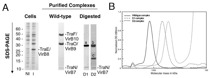
The virB7-10 gene cluster of the pKM101 plasmid was cloned and expressed (10). In this cluster, these genes are named TraN, TraE, TraO, and TraF, respectively. For clarity, each gene/protein will be named hereafter using both the Tra and VirB nomenclatures. Cloning of the traN/virB7-traF/virB10 cluster introduced a Strep-tag at the C-terminus of TraF/VirB10 (TraF/VirB10C-ST; Fig. S1, A and B). Induction of gene expression, preparation of the membrane fraction followed by solubilization of membrane proteins and a two-step purification procedure resulted in the purification of a complex containing TraN/VirB7, TraO/VirB9, and TraF/VirB10C-ST (the “wild-type core” complex (Fig. 1A) (10)). TraE/VirB8 (although strongly expressed) was not present in the purified complex. The stoichiometry of the different components of the core complex was shown to be 1:1:1 (Fig. S1C) (10). The core TraN/VirB7-TraO/VirB9-TraF/VirB10 complex purified as a ~1,100 kDa complex (Fig. 1B) (10).
Fig.1.
Purification of the pKM101-encoded T4SS complex core. A. SDS-PAGE analysis of the non-induced (NI) and induced (I) cells (left panel), the pure wild-type core complex (middle panel), and digested D1 and D2 complexes (right panel). In the right panel, “a” refers to the upper band that contains a C-terminal fragment of TraF/VirB10 and full-length TraO/VirB9; “b” refers to the top band that contains a C-terminal fragment of TraF/VirB10 and “c” refers to the middle band that contains a C-terminal fragment of TraO/VirB9. The content of the a, b, and c bands was assessed by mass spectrometry and N-terminal sequencing. B. Gel filtration of the wild-type, D1 and D2 complexes.
Wild-type core complexes were then visualized by negative stain electron microscopy (EM) (10). We observed ring-like and multi-layered particles, corresponding to end and side views of the complex, respectively (Fig. S2A). Rotational symmetry analysis of end view class-averages revealed a clear 14-fold symmetry (Fig. S2) (10). Thus, the T4SS core complex is formed of 14 copies each of 3 proteins.
The importance and role of TraN/VirB7 lipidation on core complex formation and localization were examined. TraN/VirB7 becomes acylated on Cys15 (11). This residue was mutated to Ser (TraNCys15Ser; Fig. S3A) and the resulting traN/virB7Cys15Ser-traF/virB10C-ST cluster was expressed (10). A complex (ΔL1) very similar in size to the wild-type core complex was purified (Fig. S3A). Thus, lipidation of TraN/VirB7 is not required for core complex formation. We next examined the membrane localization of the ΔL1 core complex and established that both the wild-type and ΔL1 core complexes reside in the inner membrane; however, only the wild-type core complex is found in the outer membrane (Fig. S3A) (10). Thus, lipidation of TraN/VirB7 is required for targeting of the core complex to the outer membrane. This interpretation was confirmed by accessibility studies on whole cells (Fig. S3B) (10). Finally, we investigated the role of each of the genes in the traN/virB7-traF/virB10 cluster by deleting them one at a time and demonstrated that TraE/VirB8 is not involved in the assembly of the core complex but that TraN/VirB7, TraO/VirB9 and TraF/VirB10 are essential for 14-mer ring complex formation (Fig. S3 and (10)).
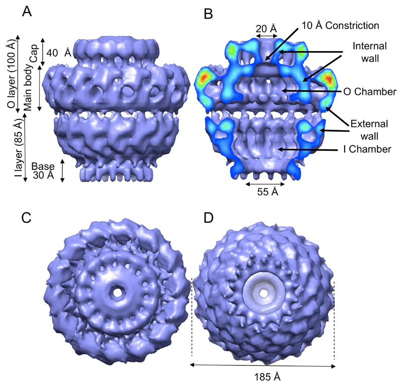
To obtain a detailed view of the three-dimensional (3D) structure of the TraN-TraO-TraFC-ST complex, a cryo-EM data set was collected and used to reconstruct a 15Å resolution 3D map of the complex with 14-fold symmetry (Fig. S4) (10). The final structure is shown in Fig. 2. The T4SS core complex has an overall dimension of 185 Å in both height and diameter (Fig. 2). It is made of two main layers, labelled inner (I) and outer (O) with reference to the orientation which will be discussed later (Fig. 2A). Both layers are either in part (the I layer) or entirely (the O layer) composed of two walls (Fig. 2B).
Fig.2.
Cryo-EM structure of the TraN/VirB7, TraO/VirB9, and TraF/VirB10C-ST core complex. A. Side-view. B. Cut-away side view. Electron density is color-coded from red to blue to indicate regions of strong to weaker density, respectively. C. Top view (view from outside the cell). D. Bottom view (view from the cytoplasm). All features and dimensions mentioned in the text are indicated.
The O layer consists of two regions: the cap which is 110 Å in diameter and 40 Å high, and the main body which is 185 Å in diameter and 60 Å high (Fig. 2A). In the cap, the internal wall forms a 20 Å hole tapering off to a 10 Å diameter constriction at the main body (Fig. 2B). In the main body, the internal wall forms a chamber (Fig. 2B), which is 110 Å wide and 30 Å high. Internal protuberances are clearly visible at the bottom of the chamber: these leave a large opening of 55 Å.
The I layer resembles a cup. It is linked to the O layer by thin linkers. The two walls of the cup merge into a single wall near the base. The internal wall defines a chamber which is as wide as the chamber in the O layer but double the height at 60 Å. This chamber tapers off at the bottom to a diameter of 55Å where it reaches the 30 Å high base from which 14 fingers of density extend downwards.
To locate specific proteins in the core complex we used limited proteolysis followed by imaging of the resulting complexes by either negative stain or cryo-EM (10). A limited proteolysis performed at low trypsin concentration (2 µg/ml) generated a first sub-complex (D1) of ~700 kDa where the residues 1-129 of TraF/VirB10 were removed from the core complex (Fig. 1). More extensive digestion with 2 mg/ml trypsin produced a second sub-complex of ~500 kDa (D2) in which residues 1-155 of TraF/VirB10 and residues 1-149 of the mature TraO/VirB9 were removed (Fig. 1).
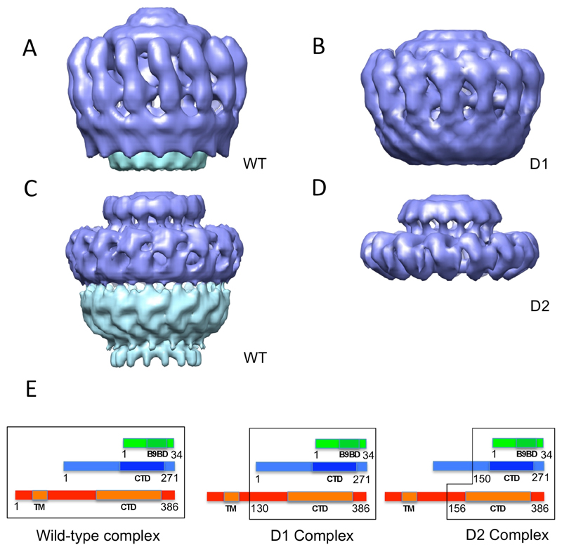
Both the D1 and D2 complexes were visualized using negative stain and a cryo-EM structure was determined for D2 (Figs. S2 and S4). Particles in the D1 negative stain and D2 negative stain EM data sets exhibited clear 14-fold symmetry (Fig. S2E). The only difference between the negative stain wild-type and D1 complex structures is the disappearance of the base in the I layer, indicating that the base is made of the N-terminus of TraF/VirB10 (Fig. 3, A and B). As this part of TraF/VirB10 is known to insert in the inner membrane, this observation was used to orientate the complex, positioning the I layer towards the inner membrane and the O layer towards the outer membrane.
Fig.3.
Comparison of the structures of the wild-type (negative stain (A) and cryo-EM (C)), D1 (negative stain (B)), and D2 (cryo-EM (D)) complexes. Parts removed by proteolysis are shown in cyan. The E panel shows schematic diagrams of the composition of each of the complexes. TraN, TraO, and TraF are in the same representation and color-coding as in Fig. S1A. Numbering for TraN and TraO are for the mature proteins (signal sequence excluded). A black outline encloses the parts of the proteins included in the various complexes.
Comparison of the cryo-EM structures of the wild-type and D2 complexes (Fig. 3, C and D) demonstrates that the structure of the O layer in the wild-type core complex is very similar to that of the D2 complex. Thus, given that the composition of the D2 complex is known (Fig. 1), we can conclude that the O layer is mainly composed of the C-terminal domain of TraF/VirB10 (TraF/VirB10Cterm; residue 156 to 386), the C-terminus of TraO/VirB9 (TraO/VirB9Cterm residues 150 to 271 of the mature protein), and TraN/VirB7 (Figs. 1 and 3E). Fourteen of each of these would give a mass of 602 kDa, consistent with the complex mass calculated from the cryo-EM map (647 kDa when the volume is calculated on the basis of a mass of 1050 kDa for the whole structure). This implies that the I layer is composed of the N-terminal regions of TraF/VirB10 and TraO/VirB9, a conclusion also supported by the small difference between the wild-type and D1 negative stain structures in the base region of the I layer.
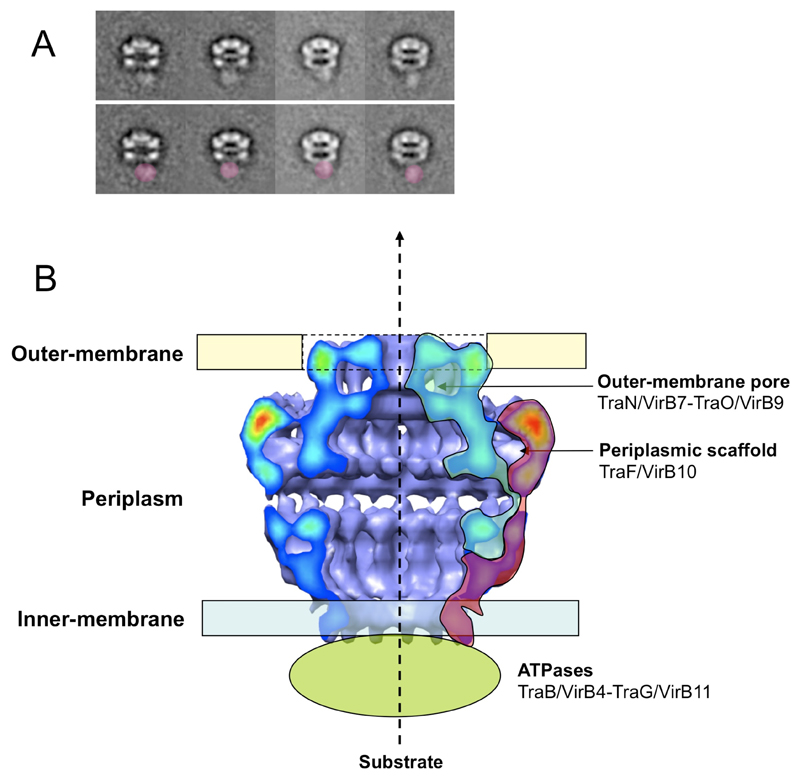
To confirm the placement of the N-terminus of TraF/VirB10 at or near the base of the I layer, a sequence encoding a His6-tag was introduced at the 5’ end of the traF/virB10 gene (resulting in the traN-N-HistraFC-ST cluster) (10). The resulting core complex is similar to the wild-type complex. When incubated with anti-His6 antibodies and imaged using negative stain EM (10), this complex shows clear additional electron density in the vicinity of the base of the I layer in both the raw data and class averages (Fig. 4A).
Fig.4.
Localization of core complex macromolecular components to the various regions of the cryo-EM structure. A. Immunolocalization of the N-terminus of TraF/VirB10 by negative stain EM. Top panel: representative class averages are shown. Lower panel: same as top panel but with additional density due to anti-His6 antibodies colored in red. B. Localization of TraO/VirB9 (blue) and TraF/VirB10 (red) within the cryo-EM structure of the wild-type core complex.
From the known data, the most likely region of the O layer to insert in the outer membrane is the C-terminal domain of TraO/VirB9 (12). The NMR structure of the C-terminal domain of TraO/VirB9 bound to TraN/VirB7 (12) shows a three-stranded β-appendage in TraO, which loosely associates with the TraO β-barrel. This β-appendage was hypothesized to undergo a large conformational change to protrude out of the cell (12). It is likely that the structure adopted by this region of the TraO/VirB9 C-terminal domain forms one of the two walls in the cap region of the O layer, suggesting that the cap is inserted in the outer membrane. Thus, the O and I chambers likely form a periplasmic channel, extending over a distance of 105 Å, a distance comparable to that observed in the WzA/WzC complex, where the two trans-membrane regions are 100 Å apart (13) (Fig. S5B).
The known structure of the C-terminal domain of the ComB10 protein (a structural prototype for C-terminal domains of VirB10 homologues) was fitted into the electron density of the external wall of the O layer’s main body, with its N-terminus directed towards the I layer (Fig. S5D) (10, 14). The rationale for locating the structure in that region is three-fold: i) in terms of shape complementarity, this is the only part of the O layer electron density where the structure can fit; ii) the goodness of fit parameter is high (0.48 as determined by SITUS (15)); iii) this external wall of the O layer is not accessible to the substrate and it has indeed been shown that, in A. tumefaciens, the substrate does not contact VirB10 directly during transfer (16). In the proposed location, VirB10 would be in an ideal position to play its role of energy transducer that has been characterized in the A. tumefaciens T4SS. In A. tumefaciens, VirB10 undergoes a conformational change induced by the inner membrane ATPases and the presence of ATP, a conformational change that is required to bring VirB9 and VirB10 together and to activate the T4SS (17). Clearly, in the pKM101 T4SS, the ATPases are not required to bring the two proteins together as the core complex forms spontaneously in the presence of the three core proteins TraN/VirB7, TraO/VirB9, and TraF/VirB10; however, they may be necessary for activation of the machinery. We suggest that ATPase function (perhaps together with VirB6 and VirB8) at the inner membrane induces conformational changes in the C-terminal domain of VirB10 that results in the opening of the constriction in the cap, required to allow passage of nucleoprotein complexes.
Our interpretation of the data presented here can be summarized in a model in which TraF/VirB10 forms the major part of the outer surface of the core complex (except the cap), while TraO/VirB9 together with TraN/VirB7 form the internal walls of the core complex. In that configuration, TraF/VirB10 would not directly take part in substrate transfer, but would play a role in reshaping the inner TraO surface to allow passage of the substrate through the O layer cap (Fig. 4B).
The structure of the core T4SS machinery presented here is very different from that of the type III secretion system (T3SS) (18) (Fig. S5C). Indeed, the components of the two systems share no sequence similarity and the envisaged multimerization order of each component is very different. T4SSs have likely evolved the architecture revealed here in order to secrete a wide variety of substrates including large DNA-protein complexes.
Supplementary Material
General sentence.
A double walled structure that spans the inner and outer membranes in Gram-negative bacteria suggests how secretion of type IV secretion virulence factors might be regulated.
Acknowledgments
This work was funded by research grants from the Wellcome Trust to GW and BBSRC to HRS and by an equipment grant from the Wellcome Trust to HRS and EVO. HRS and EVO thank the EU 3DEM Network of Excellence for support. EM maps have been deposited to the EM data bank under the entry codes EMD-5031 to EMD5035 for cryo-EM wild-type, negative stain EM wild-type, negative stain EM D1, cryo-EM D2, and negative stain ΔL2 complexes, respectively.
References
- 1.Christie PJ, Atmakuri K, Krishnamoorthy V, Jakubowski S, Cascales E. Annu Rev Microbiol. 2005;59:451. doi: 10.1146/annurev.micro.58.030603.123630. [DOI] [PMC free article] [PubMed] [Google Scholar]
- 2.Schroder G, Lanka E. Plasmid. 2005;54:1. doi: 10.1016/j.plasmid.2005.02.001. [DOI] [PubMed] [Google Scholar]
- 3.Krall L, et al. Proc Natl Acad Sci USA. 2002;99:11405. doi: 10.1073/pnas.172390699. [DOI] [PMC free article] [PubMed] [Google Scholar]
- 4.Ward DV, Draper O, Zupan JR, Zambryski PC. Proc Natl Acad Sci U S A. 2002;99:11493. doi: 10.1073/pnas.172390299. [DOI] [PMC free article] [PubMed] [Google Scholar]
- 5.Jakubowski SJ, Cascales E, Krishnamoorthy V, Christie PJ. J Bacteriol. 2005;187:3486. doi: 10.1128/JB.187.10.3486-3495.2005. [DOI] [PMC free article] [PubMed] [Google Scholar]
- 6.Baron C, Thorstenson YR, Zambryski PC. J Bacteriol. 1997;179:1211. doi: 10.1128/jb.179.4.1211-1218.1997. [DOI] [PMC free article] [PubMed] [Google Scholar]
- 7.Das A, Xie YH. J Bacteriol. 2000;182:758. doi: 10.1128/jb.182.3.758-763.2000. [DOI] [PMC free article] [PubMed] [Google Scholar]
- 8.Liu Z, Binns AN. J Bacteriol. 2003;185:3259. doi: 10.1128/JB.185.11.3259-3269.2003. [DOI] [PMC free article] [PubMed] [Google Scholar]
- 9.Harris RL, Hombs V, Silverman PM. Mol Microbiol. 2001;42:757. doi: 10.1046/j.1365-2958.2001.02667.x. [DOI] [PubMed] [Google Scholar]
- 10.Materials and methods, supporting text and figures are available as supporting materials on Science online.
- 11.Fernandez D, et al. J Bacteriol. 1996;178:3156. doi: 10.1128/jb.178.11.3156-3167.1996. [DOI] [PMC free article] [PubMed] [Google Scholar]
- 12.Bayliss R, et al. Proc Natl Acad Sci U S A. 2007;104:1673. doi: 10.1073/pnas.0609535104. [DOI] [PMC free article] [PubMed] [Google Scholar]
- 13.Collins RF, et al. Proc Natl Acad Sci U S A. 2007;104:2390. doi: 10.1073/pnas.0607763104. [DOI] [PMC free article] [PubMed] [Google Scholar]
- 14.Terradot L, et al. Proc Natl Acad Sci U S A. 2005;102:4596. doi: 10.1073/pnas.0408927102. [DOI] [PMC free article] [PubMed] [Google Scholar]
- 15.Wriggers W, Milligan RA, McCammon JA. J Struct Biol. 1999;125:185. doi: 10.1006/jsbi.1998.4080. [DOI] [PubMed] [Google Scholar]
- 16.Cascales E, Christie PJ. Science. 2004;304:1170. doi: 10.1126/science.1095211. [DOI] [PMC free article] [PubMed] [Google Scholar]
- 17.Cascales E, Christie PJ. Proc Natl Acad Sci U S A. 2004;101:17228. doi: 10.1073/pnas.0405843101. [DOI] [PMC free article] [PubMed] [Google Scholar]
- 18.Marlovits TC, et al. Science. 2004;306:1040. doi: 10.1126/science.1102610. [DOI] [PMC free article] [PubMed] [Google Scholar]
Associated Data
This section collects any data citations, data availability statements, or supplementary materials included in this article.


