Abstract
We are developing a cooperatively-controlled robot system for image-guided radiation therapy (IGRT) in which a clinician and robot share control of a 3D ultrasound (US) probe. IGRT involves two main steps: (1) planning/simulation and (2) treatment delivery. The goals of the system are to provide guidance for patient setup and real-time target monitoring during fractionated radiotherapy of soft tissue targets, especially in the upper abdomen. To compensate for soft tissue deformations created by the probe, we present a novel workflow where the robot holds the US probe on the patient during acquisition of the planning computerized tomography (CT) image, thereby ensuring that planning is performed on the deformed tissue. The robot system introduces constraints (virtual fixtures) to help to produce consistent soft tissue deformation between simulation and treatment days, based on the robot position, contact force, and reference US image recorded during simulation. This paper presents the system integration and the proposed clinical workflow, validated by an in-vivo canine study. The results show that the virtual fixtures enable the clinician to deviate from the recorded position to better reproduce the reference US image, which correlates with more consistent soft tissue deformation and the possibility for more accurate patient setup and radiation delivery.
Keywords: Image Guided Radiation Therapy (IGRT), Ultrasound Guided Radiotherapy, Interfraction Repeatability, Robot Assisted Radiotherapy
I. Introduction
Radiotherapy is commonly used as a treatment for cancer. We consider IGRT, which involves two main procedures, performed in different rooms on different days: (1) treatment planning in the simulator room, and (2) radiotherapy in the linear accelerator (LINAC) room over multiple subsequent treatment delivery days. First, the patient is placed on a simulator, which is a large-bore CT scanner, to obtain the image that will be used for planning and that will guide the patient setup for subsequent radiation treatments. Additional 3D images, such as magnetic resonance imaging (MRI), can be registered to the planning CT if necessary. Subsequently, radiation treatments are performed with a linear accelerator (LINAC); modern LINACs include on-board cone beam CT (CBCT) imaging to directly show the setup of the patient in the treatment room frame of reference. Two major deficiencies have become apparent when CBCT is applied to verify radiotherapy: (1) CBCT provides a “snapshot” of patient information only at the time of imaging, but not during actual radiation delivery, and (2) CBCT often does not provide sufficient contrast to discriminate soft tissue targets.
US imaging can overcome these deficiencies because it provides better soft tissue contrast and continuous real-time feedback. Thus, it can be used to: (1) facilitate patient setup on the treatment couch, where the objective is to place the tumor at the same location (relative to the isocenter) as on the planning day, and (2) evaluate the radiation delivery by monitoring the tumor in real-time on each treatment day. Because US imaging requires physical contact between the transducer and the patient body, its integration into the radiation treatment plan introduces some challenges. During US imaging, the pressure applied by the US probe deforms the region of contact, and thus may move and/or deform the tumor. In order to use US imaging to monitor the tumor during radiation delivery, it is necessary to develop a technique that can compensate for this deformation.
Existing commercial systems that take advantage of US imaging in radiotherapy include: BATCAM (Best NOMOS, PA), SonArray (ZMED, now Varian Medical Systems, CA) and Clarity (Resonant Medical, now Elekta AB, Stockholm, Sweden). Among these systems, BATCAM and SonArray use US imaging only for patient setup, whereas the Clarity System can utilize US imaging for both patient setup and real-time target monitoring during radiotherapy. A comparison of these systems is summarized in Table I, which presents an overview of commercial and research systems (including the one proposed here).
TABLE I.
Comparison of commercial and research systems with the proposed robotic system (*).
| Purpose of Use | US Probe | Target Area | US Probe Control | Patient Setup Validation | ||||||||
|---|---|---|---|---|---|---|---|---|---|---|---|---|
| Patient Setup | Treatment Monitoring | 3D | 2D | Lower Abdomen | Upper Abdomen | Tissue Deformation Repeatability | Manual | Fixed Arm | Robotic System | US – US Registration | US – CT Registration | |
| BATCAM | X | X | X | X | X | X | ||||||
| SonArray | X | X | X | X | X | X | ||||||
| Clarity | X | X | X | X | X | X | ||||||
| Stanford-1 | N/A | X | X | X | N/A | X | N\A | N\A | ||||
| Stanford-2 | N/A | X | X | X | X | N/A | X | N\A | N\A | |||
| Lubeck | N/A | X | X | X | N/A | X | N\A | N\A | ||||
| JHU (*) | X | X | X | X | X | X | X | X | ||||
The BATCAM and SonArray Systems have a hand-held US probe with attached optical markers. These markers are tracked by cameras mounted on the ceilings of the simulation and treatment rooms. Through a series of coordinate transformations (see Section II-B), the US image data is represented in a common room coordinate system. The workflow includes taking a reference US image on the planning day along with a reference CT image, which is used in the planning. Then, before each treatment, with visual help on the US monitor, therapists manually find the tumor. Based on the position difference of the tumor between the planning day reference image and the treatment day US image a couch shift is performed.
These systems have two limitations. First, they do not take into account the reproducibility of soft tissue deformation introduced by the US probe. It is assumed that on the planning day and on all of the treatment days, the tumor will shift by the same amount when the US probe is placed for the scan. Second, they require the therapist to get further training in ultrasonography since the process is highly dependent on the therapist’s judgment on the US images acquired.
The Clarity System focuses on the prostate and uses a transperineal 3D US probe. The primary difference compared to other commercial systems is that the US probe is attached to a passive arm mounted on the couch and collects 3D US images not only before, but also during, treatment. For patient setup, this system compares 3D US images acquired on the treatment day to the planning day reference 3D US image. Based on the tumor shift, a couch shift is applied. One drawback of this system is that it can only be used for the prostate, which is minimally affected by respiratory motion. A second drawback, similar to other commercial products, is that it does not aim to recreate the same soft tissue deformations introduced by the US probe (however, these may be small due to the use of a transperineal probe).
US imaging was previously used in radiotherapy by Troccaz et al. [1] to measure the actual position of the prostate just before irradiation, and by Sawada et al. [2] to demonstrate real-time tumor tracking for respiratory-gated radiation treatment in phantoms. Harris et al. [3] performed “speckle tracking” to measure in-vivo liver displacement in the presence of respiratory motion and Bell et al. [4] applied the technique with a higher acquisition rate afforded by a 2D matrix array probe. Other potential tracking algorithms are benchmarked by De Luca et al. [5]. Two tele-robotic systems for US monitoring of radiotherapy were developed by Schlosser et al. [6]–[8] at Stanford University. The first system is a transabdominal prostate robot. The second system is an upgraded version for abdominal use and is being commercialized by SoniTrack Systems (Palo Alto, CA). Another tele-robotic research system for US monitoring of radiotherapy was developed at Lubeck University [9] and has been tested on the hearts of healthy human subjects. The two Stanford University systems and the system at Lubeck University are detailed in the studies by Western et al. [10] and by Ammann et al. [11], respectively. The focus of these studies, however, appears to be on monitoring during the radiation beam delivery phase and not on the patient setup for simulation or treatment. Other robotic systems for ultrasonography have been introduced in areas outside radiotherapy in [12]–[22].
In this work, we developed a cooperatively-controlled robot system for US-guided radiotherapy (JHU system in Table I). Our system and all of the above robotic systems include a force sensor for monitoring and/or controlling the contact force between the probe and patient. Our system differs because the obtained force information is utilized to achieve reproducible probe placement, and therefore reproducible soft tissue deformation, with respect to the target organ. This enables accurate registration between the real-time treatment day US images and the planning day CT, which can be used to improve the patient setup and to monitor the target during treatment. In addition, our system can be used not only for pelvic organs such as the prostate, but also for abdominal organs, such as the liver and pancreas.
The first contribution of this paper is the definition of a complete workflow for introducing US imaging to assist with setup and monitoring of upper abdominal organs during radiotherapy; this extends the workflow presented in [23], which primarily focused on the planning day. Within this workflow, another contribution is the use of virtual fixtures to implement soft constraints during cooperative control, which guide the clinician (possibly with limited US experience) during placement of the probe. Additional contributions include the validation of this workflow in an in-vivo canine model. Our results show that the US imaging detected a surprising amount of organ motion between the simulated interfraction sessions (presumably due to setup errors and anatomical changes), but that the robot system enabled the user to correct for this motion and improve the consistency of the organ position and shape (deformation).
II. Materials and Methods
Real-time US monitoring introduces challenges because placement of the US probe on the patient body is likely to change the position and shape of the soft tissue target. A change in position can be compensated by shifting the couch, but it is more difficult to compensate for changes in shape (i.e., deformation). Our approach is to minimize the effect of soft tissue deformation by introducing the US probe during the acquisition of the simulation CT, so that planning is performed on the deformed tissue. In order to provide accurate radiation treatment, the same soft tissue deformations should be generated in all treatment delivery days. In this study, it is assumed that similar soft tissue deformations are obtained when the 3D US images acquired during treatment are similar to the reference 3D US image.
Because CT scanning and radiotherapy both utilize ionizing radiation, it is not feasible for the clinician to hold the probe on the patient. While a passive arm may be used (as in the Clarity System), a robot system provides greater flexibility, especially for upper abdominal organs. The following sections describe the robot system that was developed, the cooperative control method with virtual fixtures that guide placement of the probe, and the proposed workflow.
A. Robot System
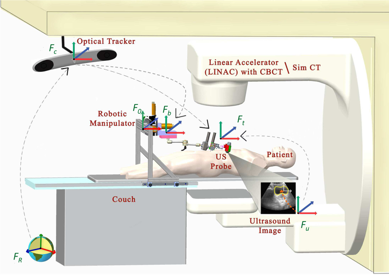
The robotic system is used during both Simulation (SIM) and treament delivery in the Linear Accelerator (LINAC), as illustrated in Fig. 1. The primary difference between these rooms is that the SIM room contains a large-bore CT scanner rather than a LINAC. We assume that each room contains an optical tracking system, attached to the ceiling of the room, that is calibrated to provide a common world reference frame. In our case, this is provided by the Clarity System (Elekta AB, Stockholm, Sweden). A description of the different coordinate frames and transformations between them is presented in Section II-B.
Fig. 1.
Radiotherapy environment: SIM room (with CT scanner) and LINAC room; each contains an optical tracking system that is typically calibrated to place the isocenter at the origin.
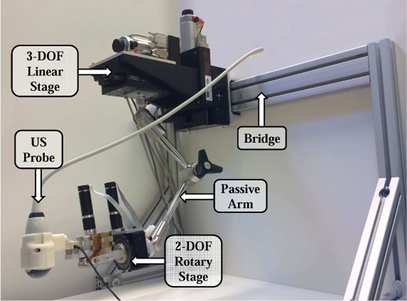
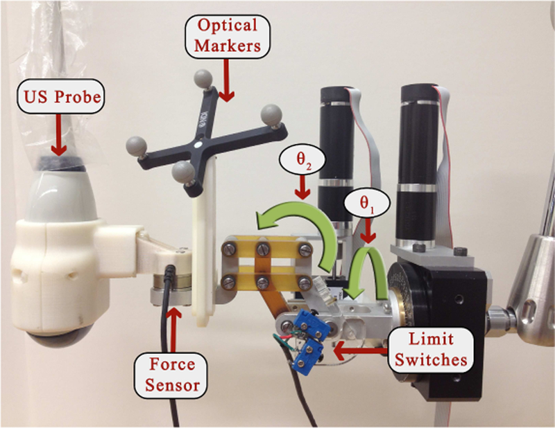
The robotic manipulator that holds the US probe is attached to the couch via a bridge, as shown in Figs. 1 and 2. The bridge contains passive linear axes and can also slide on the couch rails to provide coarse positioning of the robot base. Once the approximate position is reached, the bridge is locked to the couch. The robotic manipulator is attached to the bridge and consists of three parts: 1) a Base Robot (3-axis active linear stages), 2) a 6 degrees-of-freedom (DOF) passive arm, and 3) a Tip Robot (2 DOF active rotary stages), as shown in Fig. 3. Optical markers (reference frames) are placed on the Base Robot and Tip Robot; these enable the optical tracking system to measure the pose of the unencoded passive arm and to provide direct end-point feedback of the US probe. The US probe is provided by the Clarity System.
Fig. 2.
Robotic System for radiotherapy
Fig. 3.
2 DOF rotary stages
Because the robot contains only five motorized DOF (three translations and two rotations), the passive arm must be used to set one rotation angle. A graphical user interface (GUI) displays the reference (planning day) orientation and the current orientation of the US probe as graphical icons and Euler angles [24]. It also displays the difference between the current and reference Euler angles. The user’s goal is to set the first Euler angle difference as close to zero as possible. The motorized rotary axes will minimize the discrepancy in the other two Euler angles.
B. System Transformations
In both rooms (SIM and LINAC), there are 6 basic coordinate frames: FR (room), Fc (camera), Fb (robot base marker), Ft (robot tip marker), Fu (US image) and F0 (robot origin). There are several transformations that convert data between these frames, as presented below. Although this paper provides all necessary information, a review of the transformations (except those relating to the robot system) can also be found in a book chapter on Ultrasound-Guided Radiation Therapy [25]. In our system, the optical tracking system also tracks the robot base Fb in addition to the US probe Ft (i.e., the tracking camera directly measures the transformations between Fb and Fc and between Ft and Fc).
The Clarity System includes calibration procedures that establish the transformation between the camera coordinates, Fc, and the room coordinates, FR, as well as the transformation between the US image coordinates, Fu, and the marker frame attached to the US probe (robot tip marker), Ft. The transformation (rotation) between robot coordinates, F0, and camera coordinates, Fc, is determined via a simple calibration procedure. Specifically, the robot is first moved along its x axis, and then along its y axis, while the camera measures the robot base marker frame, Fb, with respect to the camera frame, Fc. This produces two direction vectors that are normalized and orthogonalized to form the first two columns of the rotation matrix between the camera and the robot coordinate frames. The third column vector is the cross product of the first two column vectors. The translation component is not required so it is arbitrarily set to zero.
C. Cooperative Control with Virtual Fixtures
To maneuver the US probe, we implemented a cooperative control algorithm where the robot holds the probe but the clinician applies forces on the probe that cause the robot to move. In this unconstrained mode, the robot moves in the direction of the applied force, with a velocity proportional to the force magnitude (i.e., admittance control). This mode is used on the planning day to enable the ultrasonographer to initially place the US probe.
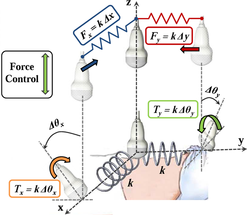
On the treatment delivery days, it is necessary to place the probe at (or near) the position and force recorded during simulation (i.e., same x,y position, orientation, and z force). While it is technically feasible for the robot to autonomously move the probe to this position, we contend that it is safer for the clinician to move the probe using cooperative control. In this case, the robot system must apply constraints that guide the clinician to the correct position and orientation. As detailed in [26], these constraints are provided by virtual linear and torsional springs, where the springs pull the probe toward the goal position and orientation (see Fig. 4). In this guidance mode, the system remains in the unconstrained cooperative control mode until the US probe crosses the x = 0 or y = 0 plane. Once a plane is crossed, a virtual spring is created and attached between the plane and the probe tip, thereby pulling the probe toward the plane. When both planes have been crossed, the result is two orthogonal springs that pull the probe toward the line formed by the intersection of the two planes (i.e., the line that passes through the goal position at x = y = 0). The virtual spring force is proportional to the displacement on that axis.
Fig. 4.
Cooperative control with virtual springs (fixtures). To prevent discontinuities, each spring is engaged when the US probe crosses the plane where zero force or torque is applied.
When the linear springs are engaged, the clinician can switch to the rotation mode to get guidance around the x and y axes via the use of torsional springs (rotation about the z axis is not possible with the current 5 DOF robot). This procedure is similar to the linear springs, where the clinician must cross the goal orientation before a torsional spring is created and applied. It should be noted that the requirement to pass through the goal position or orientation before activating the spring prevents a discontinuity in the resistive force felt by the clinician. For example, if a spring is enabled when the probe is far from the desired position, the controller would immediately apply a large force to move the probe toward the goal.
Finally, when all springs are activated and the desired position and orientation on the x and y axes are set, the clinician can enable force control along the US probe’s z axis to reproduce the force that was recorded during simulation.
The springs can implement either hard or soft virtual fixtures, depending on the specified stiffness. Very stiff springs (ideally, infinitely stiff) produce hard virtual fixtures that force the probe to the specified position and orientation. This is a direct alternative to autonomous motion. Lower stiffnesses produce soft virtual fixtures, which guide the clinician toward the specified goal, but enable him or her to deviate from this goal by applying forces/torques to override the springs. This is particularly useful when other information, such as the real-time US images, indicates that small position/orientation adjustments are necessary to compensate for anatomical or patient setup changes.
D. Proposed Workflow
In the conventional approach for treatment delivery, the patient is first positioned on the couch based on either the markers or the patient-specific mask generated on the planning day. Then, a CBCT scan is acquired and the image is registered to the simulation CT image, based on bony anatomy. This registration computes a couch shift (in the x, y, z directions) to align the CBCT image with the CT image. With this couch shift, it is assumed that a bony anatomy match between the planning day CT and the delivery day CBCT images will result in a satisfactory soft tissue match.
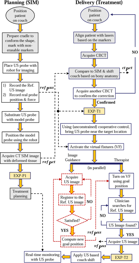
Our proposed workflow, Fig. 5, includes US imaging to assist with the patient setup and to monitor the beam delivery for organs in the lower and upper abdomen (e.g., prostate, liver, pancreas). On the planning (simulation) day, after the patient is positioned on the couch, the sonographer uses the robot in cooperative control mode, as described in Section II-C, to find the target and obtain the reference ultrasound image. The position of the US probe and the reaction force between the patient body and the US probe are saved, along with the reference US image, for use on the treatment days. Because the US probe can cause artifacts in the CT image [23], it can be substituted with an x-ray compatible model probe and placed back at the recorded position prior to acquisition of the CT simulation image. Alternatively, if the CT imaging system provides an algorithm for metal artifact reduction, it may be possible to skip these steps and acquire the CT image with the US probe in place. As yet another alternative, if the US probe pressure does not cause significant deformation of the target anatomy, the CT can be acquired without either the US or model probe in place.
Fig. 5.
Proposed workflow of radiotherapy, using US guidance/monitoring. Colored boxes are the steps for the conventional workflow; dashed boxes represent functions in development; EXP boxes indicate extra data acquisition steps performed in the experiments and are detailed in Fig. 7. Variables corresponding to specific stages are described in Section III-C
The second column of the flowchart in Fig. 5 shows the steps for the treatment delivery days. The initial setup, including CBCT to register bony anatomy to CT, is performed as in the conventional workflow. For convenience, this step can be performed without the US or model probe in place because the bony structures should not be subject to significant probe-induced deformation. Alternatively, it is possible to skip this step and use US imaging to adjust the couch, as previously demonstrated for prostate radiotherapy [27].
Whether or not an initial CBCT alignment is performed, the next step is to use US for soft tissue setup. In this case, it is necessary to place the US probe so that the target organ is in the field of view. By registering this US image to the reference US image recorded during simulation, it is possible to compute the couch shift. To improve the likelihood of a successful registration, it is advantageous to acquire an US image that is similar to the reference US image. The obvious starting point is to place the US probe at the position and orientation recorded during simulation, and to apply the same force along the probe axis. We therefore employ the cooperative control algorithm with virtual fixtures, described in Section II-C. These fixtures pull the US probe, which is attached to the robot and held by the user, towards the planning day goal position while giving the user the flexibility to override the goal position. There are three main reasons why the user may need this flexibility: 1) possible patient setup errors between planning and treatment delivery days, 2) possible changes to the patient’s anatomy (e.g., due to gas in the abdominal area), and 3) discrepancies in the calibration of the tracked ultrasound probe to the room coordinate system. If the robot forces the user to return to exactly the same position recorded during simulation, none of the above discrepancies between treatment phases would be addressed.
Our current implementation relies on the user to visually compare the real-time US image to the reference US image, both of which are displayed on the US machine monitor. Then, the user overrides the preferred position indicated by the virtual fixtures to obtain an US image that most closely matches the reference image. For ease of comparison, we acquire a 2D US image from a central elevation plane acquired with the 3D probe and compare this image to the central image of the reference 3D volume. We repeat this acquisition and comparison until the 2D images match, at which point we acquire a 3D US volume scan.
The flowchart also shows our future work (dashed boxes), which is to use US image feedback to adjust the virtual fixtures so that they guide the user to the correct probe placement. This would enable therapists with limited US experience to place the probe at the same location (relative to the patient anatomy) obtained by the experienced sonographer during simulation. Some relevant prior work in US visual-servoing can be found in [13], [28].
III. Experiments
In prior works [24], [26], we assessed the performance of the cooperative control algorithm with virtual fixtures in phantom experiments; this paper presents the results of canine experiments that were performed after approval by our Animal Care and Use Committee. We implanted three metal markers that are clearly distinguishable in CT and US images into several organs of two dogs (e.g., prostate, liver and kidney); these markers serve as surrogates for the soft tissue targets and are used for subsequent measurements. We performed experiments to evaluate the amount of soft tissue deformation due to the US probe and the repeatability of US probe placement. We then performed a complete workflow study, including planning and interfraction patient setup, for one canine.
A. Soft Tissue Deformation Due to Ultrasound Probe
We first performed experiments to investigate the amount of soft tissue deformation, for both kidney and liver, due to placement of an US probe. For each organ, we acquired a CT of the target area and recorded the implanted marker positions. An ultrasonographer then used cooperative control to place the robot-held probe so that the markers could be visualized in the US image. At this point, a second CT image was acquired and the marker positions were recorded (the CT scanner provided an artifact reduction algorithm that enabled the markers to be visualized, even with the US probe in the field of view). This procedure was performed four times for each organ, while the anesthetized canine was left undisturbed on the couch.
B. Repeatability of Ultrasound Probe Placement
The proposed workflow includes replacing the US probe with a model (non-metallic) probe to avoid CT artifact. We therefore performed intrafraction experiments, on the kidney of one canine, to quantify the repeatability of repositioning the US probe, both when the US probe is not changed and when it is replaced by the model probe. These experiments avoid patient setup error because the canine position on the couch is not changed. The experiment steps are as follows: 1) The ultrasonographer locates the metal markers; 2) A reference CT image is taken at this probe position; 3) The US probe position is saved; 4) The probe is moved up until it loses contact with the skin; 5) With the robot, the probe is accurately brought back to the saved position, following the same path; 6) A second CT image is acquired and the marker positions between the reference CT image are compared with this intrafraction CT image; 7) Steps 4–6 are repeated two more times for a total of three trials (Intra-1 to Intra-3); 8) The real probe is retracted and replaced with the dummy probe; 9) Steps 5–6 are repeated one more time (Intra-4).
The experiments are performed with breath-hold conditions that were achieved by using a respirator to hold the air in the canine lungs at end inspiration.
C. Evaluation of Proposed Workflow
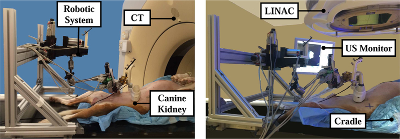
The three metal markers implanted into the kidney were the easiest to find with US, so our workflow evaluation focuses on this organ for one dog. A representative experimental setup in the simulation (SIM) and treatment (LINAC) rooms can be seen in Fig. 6.
Fig. 6.
Experimental setup: Simulation room (left) and LINAC room (right)
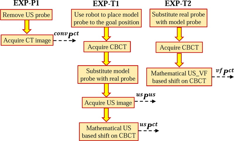
The experimental procedure for the planning phase is shown in Fig. 5. The extra data acquisition step, EXP-P1, is detailed in Fig. 7. In the diagrams, ref Pus and ref Pct correspond to the sets of marker positions in the reference US and CT images. In our experiments, each set consists of three marker positions; for example, ref Pus contains marker positions for i = 1, 2, 3.
Fig. 7.
Steps added to the proposed workflow for data acquisition purposes
In the next phase of the experiment, the dog is brought to the LINAC room for the radiotherapy delivery process. The goal is to determine how well we can reproduce the reference 3D US image, which would indicate how well we can reproduce the SIM patient setup, including the same soft tissue deformations around the target area. We obtain quantitive results by measuring the positions of the three markers. Because the focus is on reproducing soft tissue setup, we did not actually deliver radiation.
The experimental procedure in the LINAC room is shown in the proposed workflow in Fig. 5; note that extra steps (colored boxes EXP-T1 and EXP-T2) are performed to gather data for analysis and are expanded in Fig. 7. In the treatment day workflow, usPus are the marker positions in the US image when the real probe is brought to the goal position (both goal positions correspond to the position recorded on the SIM day) and usPct are the marker positions in the CBCT image when the model probe is brought to the goal position. Additionally, vf Pus and vf Pct are the marker positions in the US and CBCT images after the soft virtual fixture probe placement.
We performed two interfraction studies on each of three days, for a total of six interfraction experiments. For experiments on the same day, interfraction conditions were simulated by removing and replacing the dog in the cradle and rearranging the robot configuration, thereby generating new patient setup conditions. Due to room availability constraints, we performed all reported procedures for this canine, including simulation, in the LINAC room. There are two consequences: (1) the SIM CT image is actually a CBCT image, and (2) our results are not affected by possible differences in the calibration of room coordinates between the two rooms. Our prior work [24] includes canine results obtained in both the SIM and LINAC rooms, thereby removing the concern that this approach may succumb to an unexpected difference between the two rooms.
IV. Data Analysis
To evaluate the performance of the proposed workflow (Fig. 5), we utilized the acquired US and CBCT images during the experimental procedure and we compared interfraction marker positions with the positions recorded from the simulation US and CBCT images. The mean marker position differences, ∆p, are computed from Eq. 1:
| (1) |
where and are the ith implanted marker positions in the reference image and in each interfraction image, respectively. Note that we can use this equation for both the CT and US marker positions, and before and after the use of the virtual fixtures. To evaluate the conventional radiotherapy patient setup error without US assistance, we used convPct, shown in Fig. 5, as the reference marker.
In the proposed clinical workflow, the couch shift would be computed based on anatomical features (i.e., “Apply US based couch shift” box in Fig. 5). In our experiments, we computed the translational couch shift in room coordinates, , based on the marker positions in the US image, as follows:
| (2) |
where is the transformation matrix from US to room coordinates, provided by the Clarity System. Furthermore, since our experiments did not include radiation delivery, we did not perform this second couch shift, but rather mathematically applied it to the marker positions measured in the final CBCT image. Specifically, if represent the marker positions in the CBCT image, we apply the shift as follows:
| (3) |
where is the transformation from room coordinates to CT coordinates, provided by the LINAC. We applied the above equations to determine the couch shifts and resulting CT marker positions that would have been obtained based on the US images acquired before, usPct, and after, vf Pct, the virtual fixtures. The first case corresponds to using the US image information at the previously recorded probe position, and the second case allows the user to move the probe, with the virtual fixtures, to obtain an US image that better matches the reference image. Note that it is not necessary to apply a shift to the marker positions obtained from the US images because the robot is mounted on the couch and therefore the US probe moves with the couch (i.e., shifting the couch does not change the US image).
The above analyses focused on the marker position differences; while those differences are affected by changes in soft tissue deformation, they do not quantify the extent to which the soft tissue deformation is reproduced. The reproducibility of deformation can be evaluated by aligning the centroid of the markers in the reference CT image, , with the centroid of the markers in the interfraction CBCT image, , and then computing the magnitude of the position difference, di, for each marker i as follows:
| (4) |
We also compute the variation in probe position and orientation for all six interfraction experiments. For the position differences, we first add the computed couch shift, (Eq. 2), to the interfraction probe marker positions before subtracting them from the reference probe marker position. These measurements may be important, depending on the margin around the probe specified during planning, to ensure that radiation beams do not pass through the probe.
V. Results
A. Soft Tissue Deformation Due to Ultrasound Probe
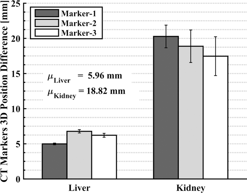
The displacement of each marker between the two conditions (without and with US probe) is displayed in Fig. 8. It is clear that the placement of the US probe creates soft tissue deformation whose magnitude depends on the organ to be monitored. For example, for the canine liver, the shift in the implanted marker positions after the probe placement is approximately 6 mm, whereas the shift increases to approximately 19 mm for the kidney. This validates our assertion (at least in a canine model) that using US imaging to monitor radiotherapy requires a method to compensate for the soft tissue deformation, so that the radiation plan remains valid for the interfraction treatment days. We have chosen to address this by introducing the deformation during planning, and then relying on the robot system to reproduce this deformation during treatment. Alternative strategies could include deformable registration between the planning and treatment images.
Fig. 8.
Displacement of each marker in CT, with and without US probe; each bar shows the mean with error bars showing ± one standard deviation of 4 measurements
B. Repeatability of Ultrasound Probe Placement
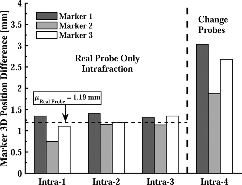
Fig. 9 shows the marker position differences between the reference CT image with the US probe in place, and the CT images taken when the same probe is repositioned (Intra-1 to Intra-3) and when it is replaced by the model probe (Intra-4). The probe placement repeatability is 2.5 mm in the latter case; this could potentially be improved by a better design of the model probe and attachment mechanism, but the results indicate that the best-case repeatability would be 1.19 mm.
Fig. 9.
Based on CT, 3D marker position differences due to removing and replacing US probe in each intrafraction experiment. Intra-1,2,3 show the error after: i) placing the real probe, ii) losing contact with the skin, and iii) bringing the probe back to the original position. Intra-4 shows the error after replacing real probe with model probe prior to last step.
C. Evaluation of Proposed Workflow
1). US Image Based Performance Comparison:
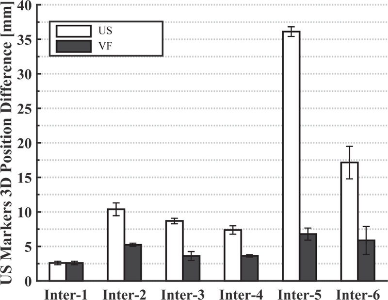
Fig. 10 (left) shows the reference (planning day) US image, where the kidney is contoured with a green dashed line. One of the implanted metal markers is also visible and is surrounded by a yellow dashed line. The middle US image is acquired on the interfraction day when the US probe is brought back to the planning day position and orientation. The metal markers are not visible in this image, and the differences are likely due to patient setup errors that were not compensated by the first couch shift and to anatomical changes that occur over time. However, after using the virtual fixtures, the US image in Fig. 10 (right) is obtained, in which the metal marker is again visible. In this case, the user visually compared the middle elevation slice of the live 3D US image to that of the reference 3D US image. The US marker position differences computed from Eq. 1 can be seen in Fig. 11. This figure shows the differences before and after the virtual fixtures. Based on these differences, a second couch shift, , is calculated with Eq. 2 to bring the target to the LINAC isocenter.
Fig. 10.
US images acquired on the planning day (left), on the interfraction day before virtual fixtures (middle), and after virtual fixtures (right)
Fig. 11.
Marker position differences (in US image coordinates) between SIM day and each interfraction day before (US) and after (VF) the virtual fixtures
2). CT Image Based Performance Comparison:
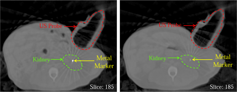
Fig. 12 shows the CBCT images in which one implanted metal marker, the plastic model probe, and the kidney are present. The left slice is from the reference (planning day) CT image and the right slice shows the same slice taken on the interfraction treatment day after the bony anatomy-based couch shift. In the right image, the metal marker is barely visible due to the setup error and/or the daily internal organ positional change.
Fig. 12.
Reference CBCT image taken on planning day (left) and CBCT taken on an interfraction day at same room coordinates (before virtual fixtures)
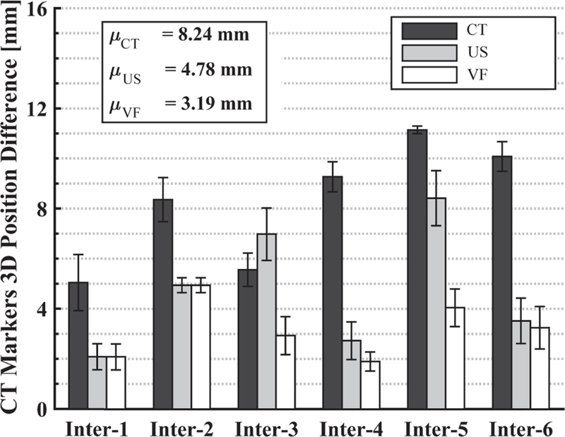
Fig. 13 shows the average position difference of the markers between the interfraction and reference CT images, computed using Eq. 1 under the following conditions: (Black) conventional approach after the first couch shift based on CT bony anatomy (marker positions are ctPct); (Gray) second couch shift based on US image, when probe is at recorded position (marker positions are usPct); (White) second couch shift based on US image obtained after user overrides recorded position, using the virtual fixtures, to find an US image that best matches the reference US image (marker positions are vf Pct). The results for US and V F are with the probe placed on the canine.
Fig. 13.
Marker position differences (in CBCT image coordinates) between SIM day and each interfraction day with: (Black) CT couch shift only, (Gray) 2nd couch shift based on US feedback at recorded probe position, (White) 2nd couch shift based on US after probe repositioned with virtual fixtures. Each bar shows the mean result of three markers.
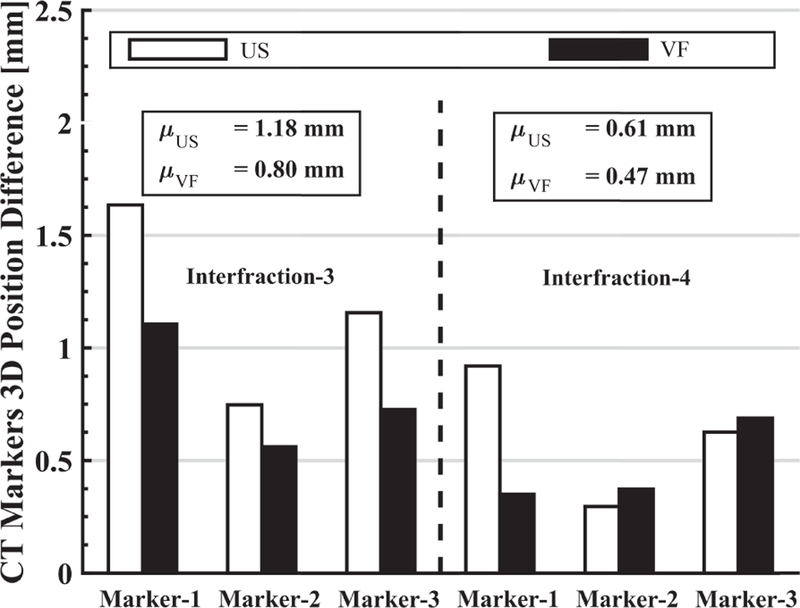
Fig. 14 shows the extent to which the soft tissue deformation is reproduced for interfraction-3 and interfraction-4. This is based on the marker position differences after aligning the centroids, as given by Eq. 4. Results for interfraction-1 and interfraction-2 are not included because the US images acquired after placing the US probe at the planning day position were sufficiently close to the reference US image; therefore, the VF was not needed. Results for interfraction-5 and interfraction-6 are not included due to lack of data. It can be seen that the use of the virtual fixture decreases the mean position differences, thereby indicating better replication of soft tissue deformation.
Fig. 14.
For interfraction-3 and interfraction-4, the 3D difference of individual marker position from the reference CBCT image marker positions when US probe placed at recorded position or adjusted with virtual fixtures.
3). US Probe Positioning Comparison:
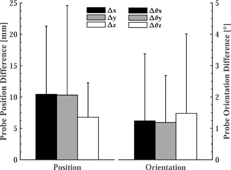
Fig. 15 shows the average probe position and orientation differences, in room coordinates, between the reference (planning) day and each of the 6 interfraction experiments. To avoid irradiating the probe, it may be necessary to move the US probe closer to the reference position and orientation. In these cases, after applying the couch shift, the therapist would move the probe toward the reference position while striving to achieve an acceptable balance between reproducing the reference US image and placing the US probe within the margins specified during treatment planning.
Fig. 15.
Based on the optical markers on the probe, the average probe position and orientation difference in all 6 interfraction experiments after the virtual fixtures.
VI. Discussion
The reported results are predominantly based on an interfraction study on the kidney of one canine. Thus, the analysis lacks statistical significance and should instead be interpreted as a validation of the proposed workflow and an informal indication of the magnitude of soft tissue variability that could be expected during fractionated radiotherapy. Furthermore, we hypothesize that the use of a canine model increased the setup error because the canine could not indicate whether it was comfortably placed in the cradle. In clinical practice, a human patient would not be anesthetized and would therefore be able to better fit into the support.
We discovered several areas for improvement of our system. In particular, adjustment of the passive arm was an inconvenience for the user and also complicated the system calibration because the kinematics between the robot tip and base required measurements from the optical tracking system. Therefore, we are developing a new system for clinical studies based on a 6-DOF robot; specifically, the UR3 (Universal Robots, Odense, Denmark) with a wrist-mounted force sensor to improve its responsiveness for cooperative control. Also, the force sensor was mounted between the US probe and the optical markers and therefore force sensor compliance can degrade the calibration of the US probe with respect to the optical tracking system.
Our results suggest that: (1) placing an US probe will cause soft tissue deformation, (2) couch shifts based on bony anatomy may not accurately bring a soft tissue target to the treatment isocenter, and (3) during interfraction treatments, placing an US probe at the same location in room coordinates will not produce the same US image as in simulation. Figure 11 shows that the metal markers can be as far as 35 mm away from the planning day positions if the US probe is returned to the planning day position, even after employing conventional patient setup procedures, such as lasers, skin markers, and couch shifts based on CBCT. This figure also shows that the virtual fixtures, which enable the clinician to adjust the probe position, dramatically reduce the error to between 2 mm and 7 mm. The greatest variance in metal marker shift was observed on the last day (interfraction 5–6), possibly due to abdominal gas.
The CT images have the benefit of showing both the metal markers and the US probe. Figure 12 shows the difference between the same slice of the interfraction CBCT image and the planning CT image, when the US probe is located at the same position in room coordinates. As with the US image comparison, this figure shows that traditional patient setup procedures do not adequately reproduce the same marker positions, which we use as a surrogate for soft tissue deformation. The dark gray bars in Fig. 13 show that if a couch shift is applied based on the bony anatomy match in CBCT, the mean position difference of the markers from the planning day positions is 8.24 mm. Computing a second couch shift based on the US images decreases this error significantly. In our experiments, we computed the second couch shift based on the difference between the centroid of the markers in the treatment image and the centroid of the markers in the reference image, as in Eq. 2, but clinically this would instead be computed by registering the soft tissue target in the two images. Figure 13 shows mean marker position differences of 4.78 mm and 3.19 mm when the second couch shift is computed from the US image acquired from the probe at the same position in room coordinates (light gray bars) and after it is repositioned by using the virtual fixtures (white bars), respectively. The latter case (virtual fixtures) produces better results due to the improved replication of soft tissue deformation.
While our results indicate improvement in patient setup, there are still several millimeters of error. We have investigated some of these error sources. First, our system relies on the ability to accurately convert US image coordinates to room coordinates. This transformation is obtained via a room calibration procedure performed by our research Clarity System. During our experiments we observed that there is approximately 5 mm of difference between the same marker positions in room coordinates calculated from CT images and US images. This relatively large discrepancy may be due to the difficulty to manually detect the center points of the implanted markers in the US and CBCT images and the calibration error in our specific setup, especially because the design of our marker frame (attached to the robot) is different than the marker frame attached to the US probe in a clinical Clarity System.
While a discrepancy of 5 mm between a marker position measured in the US image and the same marker measured in the CBCT image may appear severe, the effect on this experiment is minimal because the couch shifts are computed by subtracting marker positions measured in the same modality (i.e., US or CBCT). Because the experiments were performed in the same room, any fixed transformation error cancels out. Additionally, errors in calibration of the US probe are minimized because the probe orientation does not significantly change during the experiment.
Another source of error is the repeatability of positioning the US probe. As shown in Fig. 9, the mean marker position error due to moving the real probe up and bringing it back to the same position is 1.2 mm, and increases to about 2.5 mm when the probe is changed. Therefore, the interfraction soft virtual fixture results (3.19 mm) can be decreased by about 1.3 mm with a more robust US probe connector.
VII. Conclusions
This paper presented a cooperatively-controlled robot and a novel workflow for the integration of US imaging in the SIM and LINAC phases of IGRT for soft-tissue targets, especially in the upper abdomen where such capabilities do not yet exist clinically. The main novelty of the workflow is that the robot holds the US probe (or x-ray compatible model probe) on the patient during the acquisition of the simulation CT image; this ensures that treatment planning is performed on the deformed anatomy and with knowledge of the probe location (to avoid irradiating the probe). During treatment, US imaging is used to improve patient setup by visualizing the soft-tissue target, rather than by relying on the bony anatomy that is visible in CBCT images. Furthermore, the robot is used to accurately reproduce the deformation, thereby avoiding the need for alternative strategies, such as deformable registration, that would otherwise be required to use the US probe for real-time monitoring during treatment.
The workflow was validated by performing canine experiments, where implanted metal markers were utilized to provide quantitative measurements of the ability of the system to assist with patient setup and to reproduce the same soft tissue deformation between simulation and treatment. The results suggest that the proposed cooperative control method with soft virtual fixtures (implemented as virtual springs) can improve the reproducibility of patient setup and soft tissue deformation during the fractionated radiation treatment. The experiments also revealed that the developed robot system introduced some difficulties for the users, especially due to the requirement to manually adjust the passive arm. We are therefore changing our design to use a 6-DOF robot (Universal Robot UR3), with a wrist-mounted force sensor to enable responsive cooperative control with soft virtual fixtures. Our future work includes the use of US image feedback to adjust the virtual springs so that they more accurately guide the clinician to the correct location. This is especially important because it can eliminate the need for clinicians with ultrasound expertise during treatment. In this case, an experienced ultrasonographer would only be needed during simulation and the robot system would enable the novice user to reproduce the probe position, relative to the anatomy, defined by the expert.
ACKNOWLEDGMENT
Martin Lachaine and Rupert Brooks at Elekta (formerly, Resonant Medical) provided and supported the research version of the Clarity System that was used for this project. Judy Cook administered anesthesia and Seth Goldstein provided ultrasound assistance during the canine experiments.
This work was supported by NIH R01 CA161613
References
- [1].Troccaz J, Menguy Y, Bolla M, Cinquin P, Vassal P, Laieb N, Desbat L, Dusserre A, and Dal Soglio S, “Conformal external radiotherapy of prostatic carcinoma: requirements and experimental results,” Radiotherapy and Oncology, vol. 29, no. 2, pp. 176–183, 1993. [DOI] [PubMed] [Google Scholar]
- [2].Sawada A, Yoda K, Kokubo M, Kunieda T, Nagata Y, and Hiraoka M, “A technique for noninvasive respiratory gated radiation treatment system based on a real time 3D ultrasound image correlation: A phantom study,” Medical Physics, vol. 31, no. 2, pp. 245–250, 2004. [DOI] [PubMed] [Google Scholar]
- [3].Harris EJ, Miller NR, Bamber JC, Symonds-Tayler JRN, and Evans PM, “Speckle tracking in a phantom and feature-based tracking in liver in the presence of respiratory motion using 4D ultrasound,” Physics in Medicine and Biology, vol. 55, no. 12, p. 3363, 2010. [DOI] [PubMed] [Google Scholar]
- [4].Bell MAL, Byram BC, Harris EJ, Evans PM, and Bamber JC, “In vivo liver tracking with a high volume rate 4D ultrasound scanner and a 2D matrix array probe,” Physics in Medicine and Biology, vol. 57, no. 5, p. 1359, 2012. [DOI] [PubMed] [Google Scholar]
- [5].De Luca V, Benz T, Kondo S, König L, Lübke D, Rothlübbers S, Somphone O, Allaire S, Bell M, Chung D et al. , “The 2014 liver ultrasound tracking benchmark,” Physics in Medicine and Biology, vol. 60, no. 14, p. 5571, 2015. [DOI] [PMC free article] [PubMed] [Google Scholar]
- [6].Schlosser J, Salisbury K, and Hristov D, “Telerobotic system concept for real-time soft-tissue imaging during radiotherapy beam delivery,” Medical Physics, vol. 37, pp. 6357–6367, 2010. [DOI] [PubMed] [Google Scholar]
- [7].Schlosser J, Salisbury K, and Hristov D, “Tissue displacement monitoring for prostate and liver IGRT using a robotically controlled ultrasound system,” Medical Physics, vol. 38, p. 3812, 2011. [Google Scholar]
- [8].Schlosser JS, “Robotic ultrasound image guidance for radiation therapy,” Ph.D. dissertation, Stanford University, 2013. [Google Scholar]
- [9].Kuhlemann I, “Force and image adaptive strategies for robotised placement of 4d ultrasound probes,” Master’s thesis, University of Luebeck, 2013. [Google Scholar]
- [10].Western C, Hristov D, and Schlosser J, “Ultrasound imaging in radiation therapy: From interfractional to intrafractional guidance,” Cureus, vol. 7, no. 6, 2015. [DOI] [PMC free article] [PubMed] [Google Scholar]
- [11].Ammann N, “Robotized 4d ultrasound for cardiac image-guided radiation therapy,” Master’s thesis, University of Luebeck, 2012. [Google Scholar]
- [12].Pierrot F, Dombre E, Degoulange E, Urbain L, Caron P, Gariepy J, and louis Megnien J, “Hippocrate: A safe robot arm for medical applications with force feedback,” Medical Image Analysis, vol. 3, pp. 285–300, 1999. [DOI] [PubMed] [Google Scholar]
- [13].Abolmaesumi P, Salcudean SE, Zhu W-H, Sirouspour MR, and DiMaio SP, “Image-guided control of a robot for medical ultrasound,” IEEE Trans on Robotics and Automation, vol. 18, no. 1, pp. 11–23, 2002. [Google Scholar]
- [14].Vilchis A, Troccaz J, Cinquin P, Masuda K, and Pellissier F, “A new robot architecture for tele-echography,” IEEE Trans on Robotics and Automation, vol. 19, no. 5, pp. 922–926, 2003. [Google Scholar]
- [15].Koizumi N, Warisawa S, Hashizume H, and Mitsuishi M, “Impedance controller and its clinical use of the remote ultrasound diagnostic system,” in IEEE Intl. Conf. on Robotics and Automation (ICRA), vol. 1, 2003, pp. 676–683. [Google Scholar]
- [16].Lessard S, Bonev I, Bigras P, and Durand L-G, “Parallel robot for medical 3D-ultrasound imaging,” in IEEE Intl. Symp. on Industrial Electronics, vol. 4, 2006, pp. 3102–3107. [Google Scholar]
- [17].Conti F, Park J, and Khatib O, “Interface design and control strategies for a robot assisted ultrasonic examination system,” in Experimental Robotics Springer, 2014, pp. 97–113. [Google Scholar]
- [18].Meng B and Liu J, “Robotic ultrasound scanning for deep venous thrombosis detection using rgb-d sensor,” in IEEE Int. Conf. on Cyber Technology in Automation, Control, and Intelligent Systems (CYBER), 2015, pp. 482–486. [Google Scholar]
- [19].Pahl C and Supriyanto E, “Design of automatic transabdominal ultrasound imaging system,” in Intl. Conf. on Methods and Models in Automation and Robotics (MMAR), 2015, pp. 435–440. [Google Scholar]
- [20].Bell MAL, Kumar S, Kuo L, Sen HT, Iordachita I, and Kazanzides P, “Toward standardized acoustic radiation force-based ultrasound elasticity measurements with robotic force control,” IEEE Trans. on Biomedical Engineering, 2015. [DOI] [PMC free article] [PubMed]
- [21].Mebarki R, Krupa A, and Chaumette F, “2-D ultrasound probe complete guidance by visual servoing using image moments,” IEEE Transactions on Robotics, vol. 26, no. 2, pp. 296–306, 2010. [Google Scholar]
- [22].Zettinig O, Fuerst B, Kojcev R, Esposito M, Salehi M, Wein W, Rackerseder J, Frisch B, and Navab N, “Toward real-time 3d ultrasound registration-based visual servoing for interventional navigation,” in IEEE Intl. Conf. on Robotics and Automation (ICRA), May 2016. [Google Scholar]
- [23].Bell MAL, Ş en HT, Iordachita II, Kazanzides P, and Wong J, “In vivo reproducibility of robotic probe placement for a novel US-CT image-guided radiotherapy system,” Journal of Medical Imaging, vol. 1, no. 2, 2014. [DOI] [PMC free article] [PubMed] [Google Scholar]
- [24].Sen HT, Bell MAL, Zhang Y, Ding K, Wong J, Iordachita I, and Kazanzides P, “System integration and preliminary in-vivo experiments of a robot for ultrasound guidance and monitoring during radiotherapy,” in Intl. Conf. on Advanced Robotics, 2015, pp. 53–59. [DOI] [PMC free article] [PubMed] [Google Scholar]
- [25].Bourland J, Image-Guided Radiation Therapy Florida, FL: Taylor and Francis, 2012, ch. 2: Ultrasound-Guided Radiation Therapy. [Google Scholar]
- [26].Ş en HT, Bell MAL, Iordachita I, Wong J, and Kazanzides P, “A cooperatively controlled robot for ultrasound monitoring of radiation therapy,” in IEEE/RSJ Intl. Conf. on Intelligent Robots and Systems (IROS), 2013. [DOI] [PMC free article] [PubMed] [Google Scholar]
- [27].Robinson D, Liu D, Steciw S, Field C, Daly H, Saibishkumar EP, Fallone G, Parliament M, and Amanie J, “An evaluation of the Clarity 3D ultrasound system for prostate localization,” Journal of Applied Clinical Medical Physics, vol. 13, no. 4, 2012. [DOI] [PMC free article] [PubMed] [Google Scholar]
- [28].Krupa A, Gangloff J, Doignon C, de Mathelin MF, Morel G, Leroy J, Soler L, and Marescaux J, “Autonomous 3-D positioning of surgical instruments in robotized laparoscopic surgery using visual servoing,” IEEE Trans. on Robotics and Automation, vol. 19, no. 5, pp. 842–853, 2003. [Google Scholar]


