Abstract
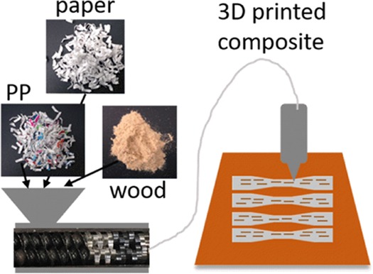
Many types of consumer-grade packaging can be used in material extrusion additive manufacturing processes, providing a high-value output for waste plastics. However, many of these plastics have reduced mechanical properties and increased warpage/shrinkage compared to those commonly used in three-dimensional (3D) printing. The addition of reinforcing materials can lead to stiffer parts with reduced distortion. This paper presents work in the reinforcement of recycled polypropylene using cellulose waste materials to generate a green composite feedstock for extrusion-based polymer additive manufacturing. Recycled polypropylene/waste paper, cardboard, and wood flour composites were made using a solid-state shear pulverization process. Fourier transform infrared and thermogravimetric analysis were utilized to qualitatively analyze the amount of filler incorporated into the 3D-printed materials. Recycled polymer composites had increased levels of filler incorporated in the printed parts compared to the virgin polymer composites based on the thermal gravimetric analysis. The dynamic mechanical analysis showed a ca. 20–30% increase in storage modulus with the addition of cellulose materials. Tensile strength was not significantly increased with the addition of 10 wt % cellulose, but the elastic modulus increased 38% in virgin polypropylene. The analysis of fracture surfaces revealed that failure initiates at the interface, suggesting that the interfacial strength is weaker than the filler strength.
Introduction
With the expansion of three-dimensional (3D) printers and low-cost extruders to fabricate a filament, the use of recycled plastics in 3D printing is expected to increase. The majority of the work has been focused on recycling acrylonitrile–butadiene–styrene (ABS) and polylactic acid (PLA).1−4 Zander et al. demonstrated the use of recycled poly(ethylene terephthalate) (PET) as well as blends of polypropylene (PP), polystyrene (PS), and PET.5,6 Baechler and Hart examined the feasibility of recycling polyethylene.7,8 In addition, there are a handful of companies that now sell recycled filaments, including Kickfly (recycled ABS), Maker Geeks (recycled PLA) and Refil (recycled glycol-modified PET (PETG), PLA, high-impact PS). Plastics recycled from virgin materials such as failed prints can generally be recycled at least once without deterioration of mechanical properties.4,9 However, most polymers from packaging materials such as polyolefins need some types of reinforcement to obtain properties on par with common commercial materials used in polymer additive manufacturing. Typical polymers used in material extrusion additive manufacturing (MEAM) have bulk tensile strengths and elastic moduli ranging between 30 and 100 MPa, 1.3 and 3.6 GPa.10 The tensile strength and modulus for bulk polypropylene and polyethylene are on the lower end or below this range at 40 MPa and 1.9 GPa and 15 MPa and 0.8 GPa, respectively.11 Note, not all packaging polymers fail to fall within this range. PET has an average strength and a modulus of 70 MPa and 3.1 GPa.12 In addition to shortcomings in mechanical properties compared to standard polymers used in MEAM, polyolefins are not typically used due to warpage and shrinkage issues resulting from their high crystallinity. In addition to improving strength and stiffness, reinforcement can minimize part distortion by decreasing thermal expansion.13,14
The use of cellulose-based materials as reinforcements for thermoplastics is becoming increasingly common. Cellulose/thermoplastic composites are now used in many applications from decking to automotive paneling. Companies like THRIVE produce a wide array of injection-molded composites from virgin and recycled polypropylene (rPP) and cellulose with applications in automotive, appliances, furniture, construction, sports and recreation, and personal and household goods. Cellulose materials, such as wood fibers, offer many advantages over synthetic reinforcing materials (e.g., glass and carbon fibers). Not only are cellulose materials abundant, renewable, and inexpensive, they also have a high specific strength and low bulk density.15 In addition, compared to glass-filled composites, cellulose composites are less abrasive, reducing wear and tear on the equipment.
There are numerous reports in the literature detailing the improved performance of composites with the addition of cellulose materials. A challenge in cellulose/polyolefin composites is the limited compatibility between the hydrophilic filler and hydrophobic matrix, leading to the lack of interfacial adhesion and also poor filler dispersion. Mechanical properties can be severely impacted since stress transfer between filler and matrix requires sufficient interfacial bonding.16 Wettability of the filler by the matrix also affects toughness. Strong particle–matrix interfacial adhesion can improve toughness due to efficient stress transfer between phases. On the other hand, poor wetting can lead to debonding, plastic void growth, and shear banding mechanisms, which absorb energy and can improve toughness.17 There has been plenty of work into coupling agents, which modify the interface, linking the composite components, to overcome these issues. Maleic anhydride-grafted polyolefins are one of the most commonly used coupling agents.18−23 Silanes and isocyanates have also been used, reacting with hydroxyl groups on the cellulose surface.21,24−26 Ito et al. found a reduced linear coefficient of thermal expansion (LCTE) in uncompatiblized cellulose/PP composites.13 Huang et al. observed similar results in bamboo PP/polyethylene composites, but the LCTE was further reduced in composites with silane-treated fillers.14 Bengtsson et al. evaluated the mechanical properties of sulfite and kraft fiber/polypropylene composites. Flexural strength and modulus were increased with the addition of filler and further increased when a maleic anhydride-grafted polymer coupling agent was used.15 Karmarkar et al. prepared a novel compatibilizer consisting of an isocyanate functional group on PP and evaluated its effect on the kraft pulp. Tensile and flexural strengths increased by 45 and 85%, respectively.27 Cantero et al. compared the effect of three different surface treatments (maleic anhydride, maleated PP, and vinyl trimethoxy silane) on flax fiber/PP composites. Composites with maleated PP had the best mechanical properties, whereas the other surface treatments had essentially no effect compared to untreated controls.28 Pickering and Ji found improvements in Young’s modulus of 77–177% for New Zealand pine-reinforced PP composites when isocyanate and maleic anhydride PP coupling agents were used.29
Dispersion of the filler is also critical to the mechanical performance of the composite and is influenced by the wetting of the polymer as well as mixing techniques. The addition of coupling agents and compatibilizers, as discussed above, leads to improved wetting and generally better dispersion. Improved dispersion can also be achieved through better mixing via a twin-screw extruder, even in the absence of a strong particle–matrix interface.17 Mathieu compared three mixing methods for the dispersion of hydroxyapatite or β-tricalcium phosphate into PLA: dry, solvent, and melt extrusion. The ceramic particles agglomerated due to van der Waals and electrostatic forces in the dry mixing case, whereas the solvent and melt extrusion led to homogenous mixing.30
Although twin-screw extrusion has many advantages in terms of high-throughput, versatility, and cost, the fabrication of biocomposites with well-dispersed fillers remains a challenge. The stresses in such a system are generally not large enough to break up agglomerates of filler, and most operating temperatures are at or above the degradation temperatures of cellulose-based fillers (200 °C). Solid-state shear pulverization (SSSP) is an approach that can potentially overcome the issue of cellulose filler dispersion and premature degradation. SSSP uses high shear and compressive forces to reduce filler size and disperse materials within a matrix material. Depending on the energy input, the process can also serve as a means of reactively compatibilizing immiscible materials via polymer chain scission and free-radical formation.31 It has been used to compatibilize polymer blends and also distribute nano- and microsized fillers in polymers.32−35 The SSSP process has been used by Iyer et al. for the fabrication of cellulose-reinforced polyolefin composites. In their work, microcrystalline cellulose (MCC) was extracted from low-cost cellulose-based waste materials such as waste paper and corrugated cardboard (CB).36,37 With the addition of 10 and 15 wt % cardboard, Young’s modulus for LDPE and PP composites increased 63 and 71%, respectively, without the addition of a coupling agent. Similar results were observed by replacing the cardboard with a waste paper. Iwamoto et al. dispersed lignocellulose nanofibers functionalized with maleic anhydride PP in polypropylene using SSSP, resulting in improved Young’s moduli, yield strengths, and toughness.38 The work by Iyer et al. suggested that a compatibilizer is not required when using the SSSP process, yet Iwamoto et al. still utilized one for their work. Thus, the question remains whether a compatibilizer is needed when processing immisible materials using SSSP and will be discussed further in the text.
The aforementioned studies are generally molded materials, but the focus of this paper is on utilizing cellulose composites for MEAM. There have been some recent works in this area. Tao et al. added 5 wt % wood flour (WF) to PLA and observed changes in microstructure and crystallinity.39 Le Duigou et al. evaluated the effects of printing parameters on ColorFabb’s WoodFill filament.40 Macadamia shells were ground and incorporated into ABS composites by Girdis et al.41 Kaynak et al. prepared PP/microcrystalline cellulose filaments for MEAM and found improvement in the tensile strength for crystals functionalized with hydrophobic silanes.42 A handful of companies also sell cellulose-based composite filaments such as Laywood (CC Products), 3D-Fuels’s Wound Up coffee and Entwined hemp filaments, and ColorFabb’s Woodfill and BambooFill.
In this work, readily available cellulose materials from waste paper, cardboard, and wood flour were incorporated into recycled and commercial of the shelf (COTS) polypropylene using the SSSP process. Powders were melt-processed into filaments for MEAM and printed into test specimens. The effect of filler loading and type was evaluated and compared to a COTS PP model system.
Results and Discussion
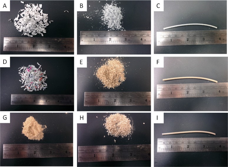
A solid-state shear pulverization process was utilized to fabricate polypropylene/celluose composites for MEAM 3D printing. The work done on the polymer by the shearing forces served to reduce the particle size of the cellulose materials. Figure 1 displays the polymer and cellulose prior to processing, SSSP powder, and resulting filament after melt processing the powder. All formulations were able to be 3D printed, but a 0.8 mm nozzle was required since some materials clogged the standard 0.5 mm nozzle. The clogging was likely due to cellulose materials that did not have sufficient size reduction during the SSSP process as well as agglomerated particles. Due to the apparent low density of the cardboard and paper materials, they did not always remain well mixed with the polymer before reaching the extruder. Thus, some materials had less polymer during the SSSP processing step to aid in shearing the cellulose and reducing particle size. Sections along the length of a filament spool were examined by scanning electron microscope (SEM) and thermogravimetric analysis (TGA) (Supporting Information, Figures S1–S3). The rPP/CB composites have a greater loading of cellulose compared to the commercial PP (cPP)/CB composites, but loading does not change significantly along the ca. 30 ft. examined. Further, weight percent remaining by TGA does not show significant differences in char along each respective filament.
Figure 1.
Recycled PP and cellulose starting materials, powder, and filament generated from SSSP. (A) Waste paper, (B) rPP/WP SSSP powder, (C) rPP/WP filament, (D) rPP shreds, (E) rPP/CB SSSP powder, (F) rPP/CB filament, (G) wood flour, (H) rPP/WF SSSP powder, (I) rPP/WF filament. WP = waste paper, CB = cardboard, WF = wood flour.
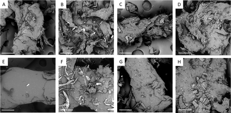
Figure 2 displays SEM images of the composite powder particles. It can be clearly seen that the cellulose particle size has been greatly reduced from millimeters to less than ca. 50 micrometers. The reduction of the filler dimension enabled facile 3D printing, as the nozzle diameter is at least one order of magnitude larger than the size of the filler.
Figure 2.
SEM images of PP/cellulose powder generated from SSSP. (A) cPP control, (B) cPP 10 wt % paper, (C) cPP 10 wt % cardboard, (D) cPP 10 wt % wood, (E) rPP control, (F) rPP 10 wt % paper, (G) rPP 10 wt % cardboard, (H) rPP 10 wt % wood. The scale bar denotes 200 μm. WP = waste paper, CB = cardboard, WF = wood flour.
Chemical analysis via Fourier transform infrared (FTIR) was utilized to qualitatively probe the composition of the cellulose filler incorporated within the printed polymer composites. Figure S4 in the Supporting Information displays the OH stretching peak for cellulose at ca. 3350 cm–1.4343 The peak is essentially absent in the pure PP and generally increases with the addition of cellulose. Figure 3 and Table 1, in which the cellulose hydroxyl stretch was normalized by the PP CH2 asymmetric stretching peak (2917 cm–1), show the trends more clearly. In general, the normalized peak areas increase with the addition of cellulose, but the trend is only linear in the rPP/CB composites. The rPP/WF composite behaves in an opposite manner, with a decreasing peak area with the addition of WF. The largest normalized peak areas for the cPP are highest for the 10 and 20% WP followed by the 20% CB. In contrast, the rPP had the highest normalized peak areas for the 20% CB followed by the 5% WF. With the exception of the WF composites, the cPP composites had higher normalized peak areas compared to the rPP composites. Dispersion appears uniform based on filament cross-sections and is not the likely reason for this difference. However, in Fourier transform infrared-attenuated total reflectance (FTIR-ATR), the beam only penetrates into the top 1–2 μm of the surface, and the surface layers of the cPP materials may have more cellulose material, or radical polymer chains could have reacted with water during processing.
Figure 3.
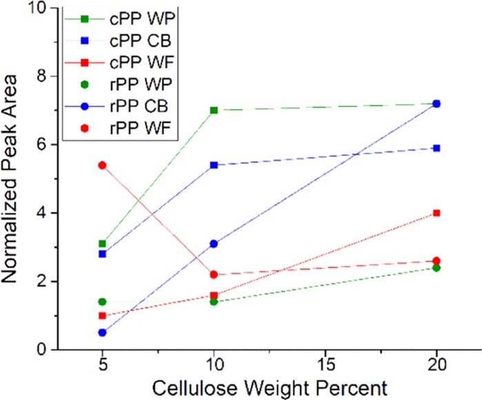
Normalized cellulose hydroxyl peak area (FTIR) as a function of cellulose composition. WP = waste paper, CB = cardboard, WF = wood flour.
Table 1. FTIR and TGA Quantification of Printed Recycled and COTs PP/Cellulose Composites.
| sample | FTIR (A3354/A2917) | TGAa (wt % at 500 °C) | TGA decomposition T (°C) |
|---|---|---|---|
| rPP | 471.8 | ||
| rPP 5% WP | 1.4 | 0.5 | 471.9 |
| rPP 10% WP | 1.4 | 0.9 | 473.2 |
| rPP 20% WP | 2.4 | 2.5 | 475.1 |
| rPP 5% CB | 0.5 | 4.9 | 470.0 |
| rPP 10% CB | 3.1 | 11.5 | 471.5 |
| rPP 20% CB | 7.2 | 15.6 | 477.6 |
| rPP 5% WF | 5.4 | 19.4 | 477.6 |
| rPP 10% WF | 2.2 | 16.8 | 478.5 |
| rPP 20% WF | 2.6 | 16.8 | 479.4 |
| cPP | 461.8 | ||
| cPP 5% WP | 3.1 | 1.5 | 458.2 |
| cPP 10% WP | 7.0 | 2.7 | 463.5 |
| cPP 20% WP | 7.2 | 6.5 | 473.5 |
| cPP 5% CB | 2.8 | 0.9 | 469.1 |
| cPP 10% CB | 5.4 | 2.1 | 460.7 |
| cPP 20% CB | 5.9 | 3.8 | 466.3 |
| cPP 5% WF | 1.0 | 1.3 | 465.3 |
| cPP 10% WF | 1.6 | 1.5 | 460.6 |
| cPP 20% WF | 4.0 | 3.5 | 467.5 |
| WP | 13.6 | 368.2 | |
| CB | 23.2 | 359.2 | |
| WF | 28.3 | 362.5 |
Controls subtracted, WP = waste paper, CB = cardboard, WF = wood flour.
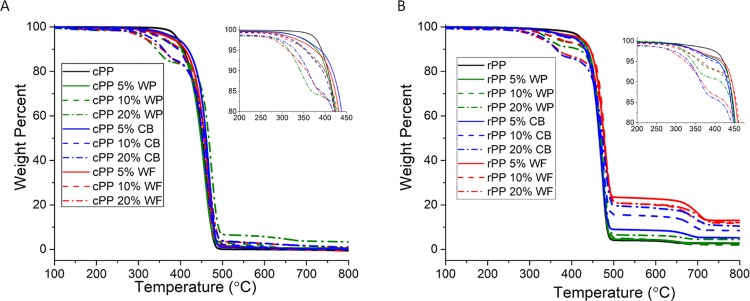
Natural cellulose materials generally have degradation temperatures, which start around 200 °C, making them unsuitable for processing above this temperature.44 Thermogravimetric analysis was used in comparison to evaluate filler loading, as well as understand the effects of the filler on thermal stability. Some weight loss is evident around 100 °C for the composites, which is attributed to moisture loss (Figure 4). The low-temperature degradation begins at 250–300 °C for the filled materials (thermal degradation of hemicelluloses) and 400 °C for the decomposition of the neat polymers. The second decomposition process occurs between 300 and 400 °C, which is attributed to the decomposition of cellulose.45 The rPP has some additional degradation occurring at ca. 650 °C, possibly due to the decomposition of additives and fillers in the recycled polymer. Table 1 presents the decomposition temperature at which the most weight loss occurred determined from the derivative weight. Graphs are presented in Supporting Information (Figure S5). The WP, CB, and WF degrade at ca. 360–370 °C when not incorporated in a polymer matrix (see Supporting Information Figure S6). The pure polymers degrade at ca. 462 °C (cPP) and 472 °C (rPP). The composites had similar thermal stability for the polymer materials, with maximum decomposition temperatures to ca. 458–479 °C.
Figure 4.
TGA of printed PP/cellulose (A) cPP, (B) rPP. WP = waste paper, CB = cardboard, WF = wood flour.
Table 1 also presents the wt % remaining at 500 °C with any contribution from the polymer subtracted. TGA of the neat cellulose materials resulted in 13–28% mass remaining at 500 °C. Thus, the masses of the composites at 500 °C were scaled by these percentages to estimate an expected mass based on the targeted composition. These estimates are shown in Table S1 in the supplementary data and compared with the measured masses.
The wt % remaining for the cPP/cellulose composites increased with filler loading and was within about 1 wt % of the expected range for the cPP series. The rPP composites also followed the trend of increased wt % remaining with increased filler with the exception of the wood flour composites. For this system, the 5 wt % composite had the highest wt % remaining. The rPP/CB and rPP/WF composites had much higher char formation than was expected. One possible cause could be uneven mixing, with the portion of the extrudate that was 3D printed having higher loadings of filler. However, this is unlikely due to the double extrusion processing that was conducted in which the extrudate was pelletized and re-extruded to make the final filament used for printing. In addition, as discussed previously, Figures S1–S3 show even filler distribution. Another cause could have been free-radical formation and cross-linking during the SSSP process, which could have changed char forming properties of the composites and/or locked in filler to matrix ratios at this processing stage. This effect may have been magnified in the rPP 5 wt % WF composites, with more polymer available to bond to the cellulose. The three types of cellulose used have different compositions with large variations in the amount of lignin, in particular, which may have also affected char formation. Wood has the highest (27%), whereas cardboard (14%) and paper (1%) have less. Paper has a secondary decomposition peak at 650 °C, which could be attributed to lignin degradation and/or impurities/chemicals from the manufacturing process, such as CaCO3.46 For the case of rPP composites, char formation was reduced with the addition of WP compared to other rPP composites, whereas the opposite trend was observed in the cPP composites. These differences can potentially be explained by the additives in the recycled polymer and the effect on char formation. Figure S7 displays FTIR spectra of rPP and cPP. There are additional peaks for the rPP material at ca. 720 and 850 cm–1.
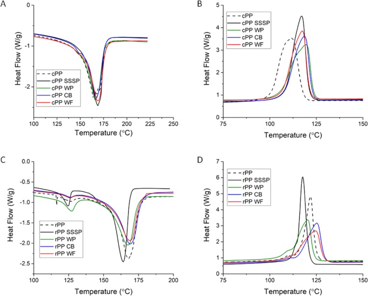
The 3D-printed composites were analyzed using differential scanning calorimetry (DSC) and dynamic mechanical analysis (DMA) to probe the thermal and mechanical properties. Cellulose fillers are generally thought of as good nucleation agents for polymer crystallization, but this depends strongly on particle size, dispersion and interfacial adhesion within the polymer matrix.47,48 Iyer et al. reported a ca. 10 °C increase in crystallization temperature and 4–8% increase in crystallinity for cellulose-reinforced PP prepared by SSSP.36 Wang et al. found the nucleation efficiency was dependent on the particle surface area and topography.49 Spherical particles with smooth surfaces had weaker nucleation ability compared to coarse fibers. Tajvidi et al. also reported an increase in crystallinity for cellulose fiber/PP composites, but only for those compatibilized with a maleic anhydride PP coupling agent.45 In this work, crystallization temperatures (Tc) increased by 1–6 °C for the recycled PP/cellulose formulations compared to the melt-processed rPP control, with the exception of the 20 wt % paper composites (Table 2 and Figure 5). Larger increases in Tc were observed for the virgin PP composites, ranging from 6 to 10 °C compared to the melt-processed cPP control. Interestingly, the SSSP processed cPP control had a 6.5 °C increase in Tc compared to the melt-processed cPP, whereas the opposite trend occurred for the rPP SSSP control. This may be related to the additives/fillers in the rPP and a reduction in the nucleation efficiency of these fillers due to the SSSP process (see FTIR in Supporting Information Figure S7).
Table 2. Thermal Transitions by DSC and DMA of Printed Recycled and COTs PP/Cellulose Composites.
| sample | Tc (°C) | Tm (°C) | Tg (tan δ) | % crystallinitya |
|---|---|---|---|---|
| rPP ctrl | 121.8 | 167.8 | 8.7 | 31.5 |
| rPP SSSP ctrl | 117.7 | 164.0 | 13.2 | 25.6 |
| rPP 5% WP | 123.6 | 166.7 | 12.2 | 31.5 |
| rPP 10% WP | 122.6 | 167.8 | 11.9 | 27.3 |
| rPP 20% WP | 120.9 | 162.8 | 11.0 | 20.3 |
| rPP 5% CB | 124.4 | 167.2 | 11.7 | 29.2 |
| rPP 10% CB | 125.3 | 169.3 | 10.0 | 25.7 |
| rPP 20% CB | 126.7 | 164.3 | 10.3 | 19.0 |
| rPP 5% WF | 127.4 | 164.8 | 12.4 | 25.8 |
| rPP 10% WF | 124.5 | 168.8 | 14.2 | 24.0 |
| rPP 20% WF | 125.7 | 163.5 | 13.0 | 19.0 |
| cPP ctrl | 111.9 | 163.7 | 14.5 | 39.2 |
| cPP SSSP ctrl | 118.4 | 164.4 | 12.3 | 41.3 |
| cPP 5% WP | 121.7 | 165.2 | 12.1 | 36.3 |
| cPP 10% WP | 119.4 | 166.2 | 8.6 | 31.4 |
| cPP 20% WP | 121.2 | 166.1 | 9.0 | 23.8 |
| cPP 5% CB | 117.7 | 164.6 | 9.0 | 38.0 |
| cPP 10% CB | 118.6 | 167.1 | 11.1 | 37.0 |
| cPP 20% CB | 118.6 | 164.8 | 10.6 | 25.0 |
| cPP 5% WF | 121.4 | 164.5 | 11.2 | 37.4 |
| cPP 10% WF | 117.4 | 168.7 | 10.1 | 38.5 |
| cPP 20% WF | 117.7 | 163.6 | 10.2 | 30.4 |
Fractional, WP = waste paper, CB = cardboard, WF = wood flour.
Figure 5.
DSC of printed PP with 10 wt % cellulose (A) cPP melting, (B) cPP crystallization, (C) rPP melting, (D) rPP crystallization. WP = waste paper, CB = cardboard, WF = wood flour.
Fractional crystallinity generally decreased with the addition of filler likely due to the larger particle sizes and poorer filler compatibility compared to the aforementioned works. To compare the SSSP process used in this work to the work of Iyer et al., the specific energy input (Ep) was calculated (Table S2). In this work, Ep was 2.7 kJ/g, whereas Iyer et al. used Ep’s ranging from 5 to 35 kJ/g. Our Ep was severely limited by the small size and torque limitations of the Process 11 extruder. Based on Iyer’s work, smaller Ep’s generally lead to larger particle sizes and reduced mechanical properties.37
The glass transition temperature, probed using DMA via tan δ, was found to be similar or reduced for the filled samples compared to the controls. This was unexpected since reinforcement generally leads to a restriction in chain motion, resulting in an increase in Tg. But Tao et al. also observed a depressed Tg, which was attributed to the poor compatibility between the filler and the matrix.39,50,51
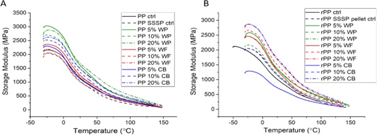
Figure 6 displays the storage modulus versus temperature for the COTS PP and rPP cellulose composites. The COTS and recycled PP controls (either processed via SSSP or solely melt processed) have similar moduli of ca. 2000 MPa. The addition of cellulose materials generally served to increase the modulus with the exception of 10 and 20 wt % WF in cPP and 5 wt % CB in rPP. The addition of paper had the greatest impact on the modulus for the cPP, whereas WF and 20 wt % CB had the most effect on rPP. It was expected that higher loadings would lead to stiffer composites, but in some cases like the cPP 5 wt % WP and WF, the lowest loading led to the highest storage modulus. It should be noted though that there is inherent uncertainty in modulus values due to variations in the thickness. Samples prepared by MEAM have additional uncertainty due to the random adhesion failure between printed roads.
Figure 6.
DMA of printed PP/cellulose (A) cPP, (B) rPP. WP = waste paper, CB = cardboard, WF = wood flour.
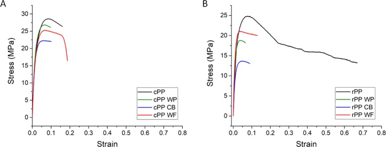
This trend was also observed in the tensile results (Figures 7 and 8). The highest tensile strengths were found in the unfilled systems due to the weak interface between the filler and polymer, with the cPP having higher strength than the rPP. The strain at failure was generally reduced as expected for the reinforced systems, with the exception of the cPP WF (17.0 ± 0.05 vs 14.5 ± 0.3%, cPP WF vs cPP control). Interestingly, this composite had the highest tensile strength and modulus of all of the composites. Many other researchers have also reported a reduction in tensile strength for unmodified cellulose fillers in PP. Samat et al. evaluated the tensile properties of injection molded recycled PP with varying amounts microcrystalline cellulose ranging from 5 to 40 wt %. Tensile strengths of composites were higher than reported in our work and averaged ca. 20–23 MPa but were also decreased compared to the unreinforced PP. The elastic moduli ranged from ca. 1000 to 1500 MPa, comparable to the 3D-printed composites.52 Kaynak et al. found modest improvements in Young’s modulus for PP with 10 wt % unmodified microcrystalline cellulose (MCC) (640–730 MPa) but reduced tensile strength.42 Tao et al. reported reduced tensile strength for PLA/WF 3D-printed composites.39 Mathew et al. found reduced tensile strength for both MCC and WF/PP composites, which was attributed to the agglomeration of the MCC crystals and poor adhesion between the filler and matrix.53 Iyer et al. reported a 21% decrease in tensile strength for PP/WP composites with specific energy inputs of 5–7 kJ/g or 2–3 times the Ep used in this work. Tensile strengths were comparable to neat PP with Ep ≥ 14 kJ/g.37
Figure 7.
Representative stress–strain curves of printed PP with 10 wt % cellulose. (A) cPP, (B) rPP. WP = waste paper, CB = cardboard, WF = wood flour.
Figure 8.
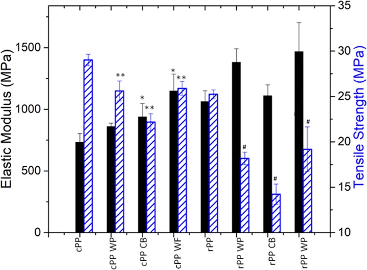
Ultimate tensile strength (hatched bars) and modulus (solid bars) of printed PP with 10 wt % cellulose. *, **, # significantly different from the respective control. WP = waste paper, CB = cardboard, WF = wood flour.
The elastic modulus was increased significantly for all of the cPP composites except the cPP/10 wt % WP. Elastic moduli increases were not statistically significant for the rPP composites, but it is clear that the average values for rPP, WP, and WF are higher than the control. There is inherently a fair amount of the scatter for samples prepared by 3D printing as well as the distribution of fillers. But in the case of the rPP polymer, there may be additional scatter due to the nonuniformity of the recycled polymer.
Many of the tensile bars curled up from the bed after printing. Certain printing techniques such as the use of a brim or raft can potentially improve adhesion and reduce warpage. In this case, a brim did not reduce warpage and a raft was not tried due to material shortages. Tensile bars with gauge regions that were distorted were not included in the results. In addition, pneumatic grips were utilized to ensure totally flat tensile specimens. Warpage is a major limitation for the use of polypropylene in additive manufacturing processes. The warpage of recycled PP is reduced compared to cPP due to the fillers and dyes added to give the packaging its desired properties. The addition of celluose-based fillers was expected to further reduce warpage, but no noticeable difference was observed by the eye. However, the composites were slightly easier to print, suggesting that the cellulose served to control shrinkage. Further characterization of warpage was outside of the scope of this work but should be addressed for the further development of such feedstocks. One method to characterize warpage is to measure the height and length of the printed part relative to the size of the model since warping occurred out-of-plane relative to the print bed.
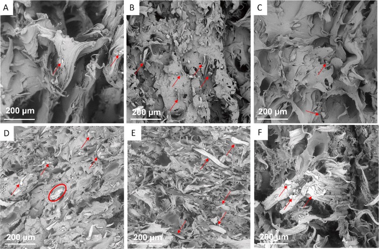
Figure 9 displays tensile fracture surfaces of the PP/cellulose composites. The Supporting Information Figure S8 displays polished fracture surfaces. The dispersion of the filler appears fairly uniform, and there is little evidence of agglomeration. Fiber pull-out and debonding are observed in all of the composite fracture surfaces, indicating a weak interface between the matrix and filler. As discussed above, a more powerful extruder/different SSSP screw configuration to achieve higher specific energy input and/or reduced particle sizes of the starting materials achieved via cryo-milling or other means could lead to improved bonding and mechanical properties.
Figure 9.
SEM images of PP/cellulose fracture surfaces. (A) cPP 10 wt % paper, (B) cPP 10 wt % cardboard, (C) cPP 10 wt % wood, (D) rPP 10 wt % paper, (E) rPP 10 wt % cardboard, (F) rPP 10 wt % wood. The scale bar denotes 200 μm. Arrows show locations of filler particles. The circle shows agglomeration of filler particles.
Materials and Methods
Mixing and Extrusion
Materials
Greek yogurt containers (Wegmans and Great Value brands) were used for the source of recycled PP (rPP). Commercial PP (cPP) was purchased from Total Petrochemicals (PPH 3270, melt flow index 2 g/10 min, density 0.905 g/cm3, melting temperature 165 °C). Office printer paper was used as the source of waste paper (WP), whereas corrugated cardboard was used for the cardboard (CB) source. Wood flour (WF) was purchased from Amazon and used as received. The cellulose sources were not dried. Recycled polypropylene (rPP) from yogurt containers was cleaned by rinsing with water, ethanol and drying in the air at room temperature. The labels were removed before cutting into pieces that could be fed into the paper shredder (Compucessory model CCS60075). Waste paper (WP) and cardboard (CB) were fed through an identical cross-paper shredder.
Melt Extrusion
Shredded rPP polymer was first consolidated into pellets using melt extrusion on a Process 11 twin-screw extruder (Thermo Scientific). The screws were fixed in an all-conveying configuration. The feed port was set at 140 °C and the adjacent zone to 170 °C to prevent clumping of the material while feeding. The following 5 zones were fixed at 180 °C. The die (2.5 mm) was set at 175 °C. The screw speed was held constant at 100 rpm. A spooler (Filabot) was used to collect the filament, which was subsequently pelletized in 1.5 mm pellets (15 m/min, Varicut Pelletizer, Thermo Scientific).
Solid-State Shear Pulverization
Composites of WP/cPP, CB/cPP, WF/cPP, WP/rPP, CB/rPP, and WF/rPP were prepared each with 3 different loadings of the cellulose material (18 different formulations). In addition, control samples of PP without cellulose were also prepared using SSSP. To prepare the composites, WP, CB, WF, and PP were weighed to generate mixtures of 5, 10, and 20 wt % loading of cellulose and hand-mixed before loading into a single screw feeder fixed above the feeding port on a Process 11 twin-screw extruder (MK2, Thermo Scientific). For the SSSP process, the screws of the Process 11 twin-screw extruder were configured to provide high shear to reduce the particle size of the filler. The 40 L/D screw design contained two areas of extreme mixing. After the feeding section, there was a 30° mixing section followed by a 60° mixing section. After the first mixing and middle conveying section, there was a long 90° mixing block and then short conveying section (see Figure 10).
Figure 10.
Screw assembly for SSSP. F = feed screws; C = conveying screws; 30°, 60°, 90° = degree mixing sections.
Filament Fabrication
The powder from the SSSP process was then melt-processed, as described above. Filament diameter uniformity from the first melt-processing step was generally quite poor due to the low density of the powder, and, thus, the extrudate was pelletized and re-extruded in a second melt-processing step, resulting in a denser filament with a diameter of 2.2 ± 0.2 mm.
Three-dimensional Printing
Both Type V tensile bars (ASTM D638) and DMA bars (35 mm × 12.5 mm × 2 mm) were printed on a Lulzbot Taz 6 MEAM printer for characterization. Recycled PP and COTS PP were printed on a clear packing tape surface with a 0.8 mm nozzle. Simplify 3D was used to for slicing and generating toolpaths and code. For all samples, a 100 °C bed temperature and a 220 °C nozzle temperature were used. A Y or flat on the bed build orientation was used, with 0.2 mm layer height, 2 shell layers, and 100% infill.54 A 45/–45° orientation for the infill was used for tensile bars and 0° for DMA bars. Tensile and DMA bar print speeds were 50 and 20 mm/s, respectively.
Materials Characterization
Chemical information was obtained via analysis by Fourier transform infrared-attenuated total reflectance (FTIR-ATR) (Thermo Nicolet Nexus 870 ESP) using 256 scans and 4 cm–1 resolution over a range of 4000–400 cm–1.
Differential scanning calorimetry (DSC) with a heat/cool program (Discovery DSC, TA Instruments) was used to evaluate thermal properties. Samples were heated at 20 °C per min to 200 °C and cooled at the same rate to −50 °C. TRIOS software (TA Instruments) was used to analyze the data. Fractional crystallinity (Xc) was calculated using the following equation
Where ΔHf is the heat of fusion of the sample, ΔHf° is the heat of fusion of a 100% crystalline PP (207 J/g), and w is the mass fraction of PP in composites.45,55
Dynamic mechanical analysis (DMA, Q800 TA Instruments) enabled characterization of the thermal–mechanical properties using the single cantilever mode. The temperature was ramped from −50 to 150 °C at a rate of 2 °C per min and a frequency of 1.0 Hz. The amplitude set-point was 200 μm. Thermogravimetric analysis (TGA) was conducted on a Q5000 (TA Instruments). All samples were heated at 20 °C per min to 800 °C under nitrogen.
Melt rheology at 180 °C was measured on an ARES G2 rheometer (TA Instruments) with 25 mm parallel aluminum plates. The gap was fixed at 1000 μm, and the shear rate was ramped from 0.1 to 10 s–1. The axial force was 20 g while taring, the strain amplitude set at 1%, and the frequency sweep was collected over 210 s.
Tensile testing was performed, as previously described.5 Briefly, uniaxial tensile experiments were performed at a displacement rate of 2 mm/min on a servohydraulic test frame with pneumatic side actuated grips (Instron, 30 psi) and 5 kN load cell (Instron model 5000R). The strain was determined from a digital image correlation system.
The morphology of the SSSP powders and broken tensile specimens was probed using a scanning electron microscope (5 kV, SEM, Phenom XL) after sputter coating with gold–palladium. Select fracture surfaces were polished by casting in epoxy cylinders with the surface of importance facing outward. Once the epoxy hardened, a polishing wheel was used with polishing compounds of a 9, 3, 1, and 1/4 μm diamond suspension in water-based slurry in succession until the desired surface finish was achieved.
Acknowledgments
J.H.P. and M.A.G. were supported by the Postgraduate Research Participation Program at the U.S. Army Research Laboratory, administered by Oak Ridge Institute of Science and Education through an interagency agreement between the U.S. Department of Energy and U.S. Army Research Laboratory (Contract ORISE 1120-1120-99).
Supporting Information Available
The Supporting Information is available free of charge on the ACS Publications website at DOI: 10.1021/acsomega.9b01564.
SEM images of the virgin PP/cardboard filament cross-sections (Figure S1); SEM images of the recycled PP/cardboard filament cross-sections (Figure S2); TGA of the PP/cardboard filament cross-sections (Figure S3); FTIR of printed PP/cellulose composites (Figure S4); TGA of derivative weight percent of printed PP/cellulose composites (Figure S5); TGA of neat cellulose fillers (Figure S6); FTIR of recycled and virgin PP (Figure S7); SEM images of polished PP/cellulose fracture surfaces (Figure S8); TGA weight percent remaining of PP/cellulose composites (Table S1); specific energy of recycled PP composites (Table S2) (PDF)
The authors declare no competing financial interest.
Supplementary Material
References
- Boldizar A.; Moller K. Degradation of ABS during repeated processing and accelerated ageing. Polym. Degrad. Stabil. 2003, 81, 359–366. 10.1016/S0141-3910(03)00107-1. [DOI] [Google Scholar]
- Mohammed M. I.; Das A.; Gomez-Kervin E.; Wilson D.; Gibson I. In EcoPrinting: Investigating the use of 100% Recycled Acrylonitrile Butadiene Styrene (ABS) for Additive Manufacturing, Proceedings of the 28th Annual International Solid Freeform Fabrication Symposium, 2017; pp 532–542.
- Anderson I. Mechanical properties of specimens 3D printed with virgin and recycled polylactic acid. 3D Print. Addit. Manuf. 2017, 4, 110–115. 10.1089/3dp.2016.0054. [DOI] [Google Scholar]
- Sanchez F. A. C.; Boudaoud H.; Hoppe S.; Camargo M. Polymer recycling in an open-source additive manufacturing context. Addit. Manuf. 2017, 17, 87–105. 10.1016/j.addma.2017.05.013. [DOI] [Google Scholar]
- Zander N. E.; Gillan M.; Lambeth R. H. Recycled polyethylene terephthalate as a new FFF feedstock material. Addit. Manuf. 2018, 21, 174–182. 10.1016/j.addma.2018.03.007. [DOI] [Google Scholar]
- Zander N. E.; Gillan M.; Burckhard Z.; Gardea F. Recycled polypropylene blends as novel 3D printing materials. Addit. Manuf. 2018, 25, 122–130. 10.1016/j.addma.2018.11.009. [DOI] [Google Scholar]
- Baechler C.; DeVuono M.; Pearce J. M. Distributed recycling of waste polymer into reprap feedstock. Rapid Prototyping J. 2013, 19, 118–125. 10.1108/13552541311302978. [DOI] [Google Scholar]
- Hart K. R.; Frketic J. B.; Brown J. R. Recycling meal-ready-to-eat (MRE) pouches into polymer filament for material extrusion additive manufacturing. Addit. Manuf. 2018, 21, 536–543. 10.1016/j.addma.2018.04.011. [DOI] [Google Scholar]
- Peinado V.; Castell P.; Garcia L.; Fernandez A. Effect of extrusion on the mechanical and rheological properties of a reinforced poly(lactic acid): reprocessing and recycling of biobased materials. Materials 2015, 8, 7106–7117. 10.3390/ma8105360. [DOI] [PMC free article] [PubMed] [Google Scholar]
- Smith W. C.; Dean R. W. Structural characteristics of fused deposition modeling polycarbonate material. Polym. Test. 2013, 32, 1306–1312. 10.1016/j.polymertesting.2013.07.014. [DOI] [Google Scholar]
- http://www.matweb.com/reference/tensilestrength.aspx.
- https://www.matbase.com/material-categories/natural-and-synthetic-polymers/thermoplastics/engineering-polymers/material-properties-of-polyethylene-terephthalate-bottle-grade-pet-bottle-grade.html#mechanical-properties.
- Ito H.; Hattori H.; Okamoto T.; Takatani M. Thermal expansion of high filler content cellulose-plastic composites. J. Wood Chem. Technol. 2010, 30, 360–372. 10.1080/02773810903537119. [DOI] [Google Scholar]
- Huang R. Z.; Zhang Y.; Xu X. W.; Zhou D. G.; Wu Q. L. Effect of hybrid mineral and bamboo fillers on thermal expansion behavior of bamboo fiber and recycled polypropylene-polyethylene composites. Bioresources 2012, 7, 4563–4574. 10.15376/biores.7.4.4563-4574. [DOI] [Google Scholar]
- Bengtsson M.; Le Baillif M.; Oksman K. Extrusion and mechanical properties of highly filled cellulose fibre-polypropylene composites. Composites, Part A 2007, 38, 1922–1931. 10.1016/j.compositesa.2007.03.004. [DOI] [Google Scholar]
- Pickering K. L.; Efendy M. G. A.; Le T. M. A review of recent developments in natural fibre composites and their mechanical performance. Composites, Part A 2016, 83, 98–112. 10.1016/j.compositesa.2015.08.038. [DOI] [Google Scholar]
- Bain E. D.; Mrozek R. A.; Lenhart J. L. Role of weak particle-matrix interfacial adhesion in deformation and fracture mechanisms of rigid particulate-filled poly(methyl methacrylate). Mech. Mater. 2017, 104, 1–12. 10.1016/j.mechmat.2016.09.014. [DOI] [Google Scholar]
- Felix J. M.; Gatenholm P. The nature of adhesion in composites of modified cellulose fibers and polypropylene. J. Appl. Polym. Sci. 1991, 42, 609–620. 10.1002/app.1991.070420307. [DOI] [Google Scholar]
- Sain M.; Suhara P.; Law S.; Bouilloux A. Interface modification and mechanical properties of natural fiber-polyolefin composite products. J. Reinf. Plast. Compos. 2005, 24, 121–130. 10.1177/0731684405041717. [DOI] [Google Scholar]
- Li H. J.; Sain M. M. High stiffness natural fiber-reinforced hybrid polypropylene composites. Polym. Plast. Technol. Eng. 2003, 42, 853–862. 10.1081/PPT-120024999. [DOI] [Google Scholar]
- Bataille P.; Ricard L.; Sapieha S. Effects of cellulose fibers in polypropylene composites. Polym. Compos. 1989, 10, 103–108. 10.1002/pc.750100207. [DOI] [Google Scholar]
- Kazayawoko M.; Balatinecz J. J.; Matuana L. M. Surface modification and adhesion mechanisms in woodfiber-polypropylene composites. J. Mater. Sci. 1999, 34, 6189–6199. 10.1023/A:1004790409158. [DOI] [Google Scholar]
- Gonzalez C.; Clemons C. M.; Myers G. E.; Harten T. M. Effects of several ingredient variables on mechanical-properties of wood fiber-polyolefin composites blended in a thermokinetic mixer. Mater. Res. Soc. Symp. Proc. 1992, 226, 127–135. 10.1557/PROC-266-127. [DOI] [Google Scholar]
- Maldas D.; Kokta B. V.; Daneault C. Influence of coupling agents and treatments on the mechanical-properties of cellulose fiber-polystyrene composites. J. Appl. Polym. Sci. 1989, 37, 751–775. 10.1002/app.1989.070370313. [DOI] [Google Scholar]
- Raj R. G.; Kokta B. V.; Daneault C. Effect of chemical treatment of fibers on the mechanical-properties of polyethylene-wood fiber composites. J. Adhes. Sci. Technol. 1989, 3, 55–64. 10.1163/156856189X00056. [DOI] [Google Scholar]
- Raj R. G.; Kokta B. V.; Maldas D.; Daneault C. Use of wood fibers in thermoplastics VII. The effect of coupling agents in polyethylene-wood fiber composites. J. Appl. Polym. Sci. 1989, 37, 1089–1103. 10.1002/app.1989.070370420. [DOI] [Google Scholar]
- Karmarkar A.; Chauhan S. S.; Modak J. M.; Chanda M. Mechanical properties of wood-fiber reinforced polypropylene composites: Effect of a novel compatibilizer with isocyanate functional group. Composites, Part A 2007, 38, 227–233. 10.1016/j.compositesa.2006.05.005. [DOI] [Google Scholar]
- Cantero G.; Arbelaiz A.; Llano-Ponte R.; Mondragon I. Effects of fibre treatment on wettability and mechanical behaviour of flax/polypropylene composites. Compos. Sci. Technol. 2003, 63, 1247–1254. 10.1016/S0266-3538(03)00094-0. [DOI] [Google Scholar]
- Pickering K. L.; Ji C. The effect of poly methylene(polyphenyl isocyanate) and maleated polypropylene coupling agents on New Zealand radiata pine fiber-polypropylene composites. J. Reinf. Plast. Compos. 2004, 23, 2011–2024. 10.1177/0731684404041139. [DOI] [Google Scholar]
- Mathieu L. M.; Bourban P. E.; Manson J. A. E. Processing of homogeneous ceramic/polymer blends for bioresorbable composites. Compos. Sci. Technol. 2006, 66, 1606–1614. 10.1016/j.compscitech.2005.11.012. [DOI] [Google Scholar]
- Tao Y.; Kim J.; Torkelson J. M. Achievement of quasi-nanostructured polymer blends by solid-state shear pulverization and compatibilization by gradient copolymer addition. Polymer 2006, 47, 6673–6681. 10.1016/j.polymer.2006.07.041. [DOI] [Google Scholar]
- Wakabayashi K.; Pierre C.; Dikin D. A.; Ruoff R. S.; Ramanathan T.; Brinson L. C.; Torkelson J. M. Polymer-graphite nanocomposites: Effective dispersion and major property enhancement via solid-state shear pulverization. Macromolecules 2008, 41, 1905–1908. 10.1021/ma071687b. [DOI] [Google Scholar]
- Wakabayashi K.; Lebovitz A. H.; Tao Y.; Torkelson J. M.. Solid-State-Shear Pulverization for Effective Dispersion and Compatibilization in Polymer Blends: Micro- and Nanoscale Morphology. In Abstracts of Papers of the American Chemical Society; American Chemical Society: Washington, DC, 2007; Vol. 233. [Google Scholar]
- Pujari S.; Ramanathan T.; Kasimatis K.; Masuda J.; Andrews R.; Torkelson J. M.; Brinson L. C.; Burghardt W. R. Preparation and characterization of multiwalled carbon nanotube dispersions in polypropylene: melt mixing versus solid-state shear pulverization. J. Polym. Sci., Part B: Polym. Phys. 2009, 47, 1426–1436. 10.1002/polb.21744. [DOI] [Google Scholar]
- Diop M. F.; Burghardt W. R.; Torkelson J. M. Well-mixed blends of HDPE and ultrahigh molecular weight polyethylene with major improvements in impact strength achieved via solid-state shear pulverization. Polymer 2014, 55, 4948–4958. 10.1016/j.polymer.2014.07.050. [DOI] [Google Scholar]
- Iyer K. A.; Flores A. M.; Torkelson J. M. Comparison of polyolefin biocomposites prepared with waste cardboard, microcrystalline cellulose, and cellulose nanocrystals via solid-state shear pulverization. Polymer 2015, 75, 78–87. 10.1016/j.polymer.2015.08.029. [DOI] [Google Scholar]
- Iyer K. A.; Lechanski J.; Torkelson J. M. Green Polypropylene/waste paper composites with superior modulus and crystallization behavior: optimizing specific energy in solid-state shear pulverization for filler size reduction and dispersion. Composites, Part A 2016, 83, 47–55. 10.1016/j.compositesa.2015.09.011. [DOI] [Google Scholar]
- Iwamoto S.; Yamamoto S.; Lee S. H.; Endo T. Solid-state shear pulverization as effective treatment for dispersing lignocellulose nanofibers in polypropylene composites. Cellulose 2014, 21, 1573–1580. 10.1007/s10570-014-0195-5. [DOI] [Google Scholar]
- Tao Y. B.; Wang H. L.; Li Z. L.; Li P.; Shi S. Q. Development and application of wood flour-filled polylactic acid composite filament for 3D printing. Materials 2017, 10, 339–344. 10.3390/ma10040339. [DOI] [PMC free article] [PubMed] [Google Scholar]
- Le Duigou A.; Castro M.; Bevan R.; Martin N. 3D printing of wood fibre biocomposites: From mechanical to actuation functionality. Mater. Des. 2016, 96, 106–114. 10.1016/j.matdes.2016.02.018. [DOI] [Google Scholar]
- Girdis J.; Gaudion L.; Proust G.; Loschke S.; Dong A. Rethinking timber: investigation into the use of waste macadamia nut shells for additive manufacturing. JOM 2017, 69, 575–579. 10.1007/s11837-016-2213-6. [DOI] [Google Scholar]
- Kaynak B.; Spoerk M.; Shirole A.; Ziegler W.; Sapkota J. Polypropylene/cellulose composites for material extrusion additive manufacturing. Macromol. Mater. Eng. 2018, 303, 1800037 10.1002/mame.201800037. [DOI] [Google Scholar]
- Fan M.; Dasong D.; Huang B.. Fourier Transform Infrared Spectroscopy For Natural Fibres, Fourier Transform-Materials Analysis; IntechOpen: Rijeka, Croatia, 2012. [Google Scholar]
- Rashid M. M.; Samad S. A.; Gafur M. A.; Qadir M. R.; Chowdhury A. M. S. Effect of reinforcement of hydrophobic grade banana (musa ornata) bark fiber on the physicomechanical properties of isotactic polypropylene. Int. J. Polym. Sci. 2016, 2016, 9017956 10.1155/2016/9017956. [DOI] [Google Scholar]
- Tajvidi M. T. A. Thermal degradation of natural fiber-reinforced polypropylene composites. J. Thermoplast. Compos. Mater. 2010, 23, 281–298. 10.1177/0892705709347063. [DOI] [Google Scholar]
- Števulova N.; Hospodárova V.; Estokova A. Study of thermal analysis of selected cellulose fibres. Geosci. Eng. 2016, 62, 18–21. 10.1515/gse-2016-0020. [DOI] [Google Scholar]
- Siqueira G.; Fraschini C.; Bras J.; Dufresne A.; Prud’homme R.; Laborie M. P. Impact of the nature and shape of cellulosic nanoparticles on the isothermal crystallization kinetics of poly(epsilon-caprolactone). Eur. Polym. J. 2011, 47, 2216–2227. 10.1016/j.eurpolymj.2011.09.014. [DOI] [Google Scholar]
- Quillin D. T.; Caulfield D. F.; Koutsky J. A. Crystallinity in the polypropylene/cellulose system .1. nucleation and crystalline morphology. J. Appl. Polym. Sci. 1993, 50, 1187–1194. 10.1002/app.1993.070500709. [DOI] [Google Scholar]
- Wang L. G.; Gramlich W. M.; Gardner D. J.; Han Y.; Tajvidi M. Spray-dried cellulose nanofibril-reinforced polypropylene composites for extrusion-based additive manufacturing: nonisothermal crystallization kinetics and thermal expansion. J. Compos. Sci. 2018, 2, 7 10.3390/jcs2010007. [DOI] [Google Scholar]
- Chung H. J.; Lee E. J.; Lim S. T. Comparison in glass transition and enthalpy relaxation between native and gelatinized rice starches. Carbohydr. Polym. 2002, 48, 287–298. 10.1016/S0144-8617(01)00259-4. [DOI] [Google Scholar]
- Lee S. Y.; Kang I. A.; Doh G. H.; Yoon H. G.; Park B. D.; Wu Q. L. Thermal and mechanical properties of wood flour/talc-filled polylactic acid composites: Effect of filler content and coupling treatment. J. Thermoplast. Compos. Mater. 2008, 21, 209–223. 10.1177/0892705708089473. [DOI] [Google Scholar]
- Samat N.; Motsidi S. N. R.; Lazim N. H. M. Effects of electron beam radiation dose on the compatibilization behaviour in recycled polypropylene/microcrystalline cellulose composites. IOP Conf. Ser.: Mater. Sci. Eng. 2018, 290, 012034 10.1088/1757-899X/290/1/012034. [DOI] [Google Scholar]
- Mathew A. P.; Oksman K.; Sain M. Mechanical properties of biodegradable composites from poly lactic acid (PLA) and microcrystalline cellulose (MCC). J. Appl. Polym. Sci. 2005, 97, 2014–2025. 10.1002/app.21779. [DOI] [Google Scholar]
- Keane P.What Is Design for Additive Manufacturing. https://www.engineersrule.com/design-additive-manufacturing/.
- Sichina W. J.http://www.perkinelmer.com/Content/applicationnotes/app_thermalcrystallinitythermoplastics.pdf.
Associated Data
This section collects any data citations, data availability statements, or supplementary materials included in this article.


