

Study shows the repair of enamel via a biomimetic growth frontier that is constructed from calcium phosphate ion clusters.
Abstract
The regeneration of tooth enamel, the hardest biological tissue, remains a considerable challenge because its complicated and well-aligned apatite structure has not been duplicated artificially. We herein reveal that a rationally designed material composed of calcium phosphate ion clusters can be used to produce a precursor layer to induce the epitaxial crystal growth of enamel apatite, which mimics the biomineralization crystalline-amorphous frontier of hard tissue development in nature. After repair, the damaged enamel can be recovered completely because its hierarchical structure and mechanical properties are identical to those of natural enamel. The suggested phase transformation–based epitaxial growth follows a promising strategy for enamel regeneration and, more generally, for biomimetic reproduction of materials with complicated structure.
INTRODUCTION
Biomineralization produces numerous biological composites with excellent mechanical performance, of which tooth enamel is the hardest (1, 2). The primary mineral phase [~96 weight % (wt %)] of enamel consists of nonstoichiometric fluoridated carbonate apatite crystals (3, 4) that are tightly packed with well-defined orientations to ensure a high striking strength (5, 6). In general, hydroxyapatite [HAP; Ca10(PO4)6(OH)2] is used as a simplified mineral model to investigate enamel formation and reconstruction (7–10). Although enamel formation (amelogenesis) is a part of the overall process of biological development, mature enamel is acellular and scarcely self-repaired after damage (11). Therefore, caries or dental decay is one of the most prevalent chronic diseases in humans worldwide (12). Despite the great attempts made at enamel remineralization by using various strategies, such as direct solution mineralization (13, 14), protein/peptide-induced mineralization (15–17), hydrogel-driven mineralization (7, 18, 19), and precursor assembly (8, 9, 20), no applicable repair for clinical development has been achieved because the complicated hierarchical structure of natural enamel cannot be replicated at large scale in laboratories.
During the biomineralization of hard tissue, the microstructures of natural materials are precisely controlled and duplicated (21). There is growing evidence that biomineralization at the growth frontier occurs in an integrated crystalline-amorphous interface: The crystalline mineral phase is coated by its amorphous phase (precursor) to ensure continuous epitaxial construction (e.g., the crystal growth frontiers of the zebrafish fin bone and nacre) (22–25). Inspired by these biological processes, we suggest that a rationally designed structure between HAP and amorphous calcium phosphate [ACP; Ca3(PO4)2·nH2O] may mimic the biomineralization frontier to induce the epitaxial regeneration of enamel.
However, the epitaxial growth of enamel with a foreign ACP phase has not been achieved in vitro. Our previous study demonstrated that ~20-nm ACP particles can adsorb and even assemble onto enamel HAP crystals, but these particles failed to induce the epitaxial growth of enamel crystals (8). In general, coalescence and fusion between particles occur more readily at smaller sizes (26). Accordingly, a question arises: What is the minimum size of the ACP particles that can be used in HAP growth studies? Recent studies have suggested that both Posner’s clusters, which are 0.95 nm in size (27), and calcium phosphate ion clusters (CPICs), with sizes of a few nanometers (28), can serve as the basic building blocks of ACP and HAP (29, 30). However, these ultrasmall ion clusters themselves are extremely unstable and can spontaneously aggregate and even nucleate within a few seconds (28). Although several additive-stabilized CPICs (31, 32), especially polymer-induced liquid precursor, have been proposed and synthesized, they cannot be applied to the repair of enamel, which is almost purely inorganic, because the irremovable organics would destroy the integrity of the enamel mineral phase, weakening the exceptional mechanical strength of this hard tissue.
We herein suggest a new type of CPICs that is stabilized by removable small organic molecules, which can establish a biomimetic crystalline-amorphous mineralization frontier to induce the epitaxial growth of enamel with a precise maintenance of the original structural complexity.
RESULTS
Characterization of CPICs
Different from other irremovable organic additives, especially polymers, triethylamine (TEA) is a small molecule that easily volatilizes in ambient environments. Our study revealed that TEA is an effective stabilizer of CPICs, and its controllable removal can result in pure HAP formation. We generated our CPICs on a large scale by mixing two ethanol solutions: one containing phosphoric acid (H3PO4; 9.8 mM) and another containing calcium chloride dihydrate (CaCl2·2H2O; 13.1 mM) and TEA (263.0 mM). Transmission electron microscopy (TEM; Fig. 1A) images show clusters with an average diameter of 1.5 ± 0.3 nm, and dynamic light scattering (DLS) measurements confirmed their size of 1.6 ± 0.6 nm, in line with previously reported cluster sizes (1.0 to 1.6 nm) (28). In contrast to other ultrasmall clusters, the resulting CPICs were stable in ethanol for at least 2 days without any aggregation or size increase (fig. S1). We confirmed the stabilizing effect of TEA on the CPICs by Fourier transform infrared (FTIR) spectroscopy and nuclear magnetic resonance (NMR) spectroscopy. The stretching vibrations of C─N in the FTIR spectrum indicated the presence of TEA in the CPICs. Typically, this peak arose at 1200 cm−1 in ethanol solution (fig. S2A) but shifted to 1203 cm−1 in the CPICs (Fig. 1B), indicating the interaction between the TEA and the CPICs. In the NMR spectra, the chemical shift (δ) of the TEA methylene protons was 2.56 parts per million (ppm) for free TEA but 3.01 ppm for TEA in the CPICs (Fig. 1C and fig. S2B); meanwhile, the δ of the 31P of PO43− in the CPICs shifted from 0 (free H3PO4) to −3.03 ppm because of the presence of TEA (fig. S2C), reflecting the interaction with TEA. The binding between TEA and phosphate results in the stabilization effect of TEA on CPICs.
Fig. 1. Synthesis and characterization of CPICs and the manufacture of bulk ACP.
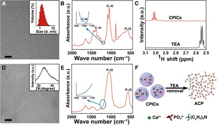
(A) TEM image of CPICs. Inset: DLS size distributions of the CPICs in ethanol solution. (B) FTIR spectra of the gel-like CPICs. a.u., arbitrary units. (C) 1H NMR spectra of TEA and CPICs. (D) SEM image of bulk ACP formed on glass, which was fabricated by the aggregation and fusion of CPICs with solvent volatilization. Inset: X-ray diffraction (XRD) of bulk ACP. (E) FTIR spectra of bulk ACP materials. (F) Schematic of ACP formation as the stabilizer (TEA) was removed by using CPICs. Scale bars, 20 nm (A) and 5 μm (D).
Construction of a mimetic biomineralization frontier
However, TEA is volatile and can be readily removed from the CPIC solution with ethanol evaporation. With ethanol volatilization at room temperature, the content of TEA in the CPICs continued to decrease to initiate ACP formation, which could be explained by the reduced stability (Fig. 1, D and F). Because no ethanol or TEA could be detected in the resulting bulk ACP by FTIR spectroscopy (Fig. 1E) or gas chromatography–mass spectrometry (GC-MS; fig. S2D), we completely removed the organics including TEA during the material evolution, ensuring pure inorganic calcium phosphate production. In contrast to the other bulk ACP (fig. S3, B to D) consolidated from nanoparticles (fig. S3A), no particle, grain, or material boundaries could be observed within the CPIC-induced ACP by scanning electron microscopy (SEM; Fig. 1D) and atomic force microscopy (AFM; fig. S4), implying a structural continuity. This structural continuity can be extended to HAP-ACP interface to establish the mimetic biomineralization frontier. By loading onto a TEM grid, the synthetic single-crystalline HAP rods (fig. S5) were dipped into a CPIC ethanol solution and then withdrawn (Fig. 2A). After an air dry treatment, the observation under high-resolution TEM (HRTEM) showed that a continuous ACP layer first formed onto the HAP. Subsequently, the epitaxial growth of the HAP crystal along the c-axial direction occurred (Fig. 2, A to C). The amorphous character of the ACP layer was proven by selected area electron diffraction (SAED; Fig. 2B, inset), and the elements were analyzed by using energy-dispersive x-ray spectroscopy (EDXS) (fig. S6C). It should be emphasized that the resulting ACP layer from the CPICs was well integrated onto the HAP without any gap. Because the crystalline phase is directly and tightly covered with a continuous layer of the disordered amorphous phase, this established HAP-ACP for epitaxial growth is exactly the same as the previously found biomineralization frontier in nature (22–25, 33). In contrast, no conventional ACP (with a typical size of ~20 nm) could construct such a structurally continuous interface from the crystalline to amorphous phase because the substrate-particle boundary cannot be avoided (fig. S6, A and D) (34). Although these ACP particles adsorbed onto the HAP rod with the subsequent crystallization, the existing crystal-particle boundary blocked the epitaxial growth from HAP to ACP, resulting in polycrystals (fig. S6B). Therefore, the observed directional growth is attributed to the continuous integration of HAP and ACP rather than the particle attachment. Analogously, the directional crystallization in biomineralization is suggested as an epitaxial solid-state transition at the well-established crystalline-amorphous interface (22, 24, 25, 35).
Fig. 2. Construction of a mimetic biomineralization frontier for epitaxial crystal growth by using CPICs.
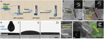
(A) Schematic of the epitaxial growth of crystalline HAP from the construction of the amorphous frontier on its surface. (B) The HAP crystal (marked with a yellow dotted line) coated with a continuous ACP layer (marked with a blue dotted line). Inset: SAED pattern of the amorphous layer. (C) The epitaxial growth of HAP was detected in the exact same region as in (B). The new crystal regrowth is marked with a red dotted line. Inset: SAED pattern of HAP and regrown crystal, which indicates that these crystals are aligned parallel to the crystallographic c axis of the HAP. (D) A CPIC ethanol solution dropped on the surface of enamel and air-dried for 15 min. (E) Cross-sectional SEM image of enamel coated with an ACP layer. (F) HRTEM image of a focused ion beam (FIB)–prepared ultrathin section of enamel coated with a continuous ACP layer (green region). Inset: SAED patterns of the original enamel rod and repaired layer. Scale bars, 10 nm (B and C), 1 mm (D), 1 μm (E), 50 nm (F), 2 nm−1 (C, inset), and 5 nm−1 (F, inset).
The application of a biomimetic frontier can be extended to enamel repair for epitaxial construction. Figure 2D shows that the CPICs exhibited excellent biocompatibility with the native enamel, which was reflected by their perfect wettability. In this experiment, we dropped 100 μl of a CPIC ethanol solution (2 mg/ml) on an enamel window (4 mm by 5 mm). After air-drying at room temperature for 15 min, an ~3-μm ACP layer was found as a continuous coating on the enamel surface (Fig. 2E). The details of the enamel-ACP interface revealed by HRTEM observation demonstrate the structural integration and continuity of the boundary between the enamel and the resulting ACP (Fig. 2F).
CPIC-repaired tooth enamel
Human enamel is characterized by a well-organized structure with hierarchical complexity: Well-aligned enamel rods are interwoven with inter-rods, which produces the characteristic “fish scale–shaped” structure (36, 37). In general, enamel rods run in a perpendicular direction to the enamel surface, and inter-rod enamel is at an angle of approximately 60° to the enamel rods (37). Although there have been many attempts at enamel remineralization, none could reproduce the characterized fish scale–shaped structure. However, this unique feature of natural enamel could be precisely replicated within 48 hours by using the CPIC material. The repaired enamel had the same morphological texture as native enamel because they were indistinguishable by SEM (Fig. 3, A and C). The boundary between the repaired and native enamel (protected by nail varnish during the repair) demonstrates successful epitaxial growth, and we also confirmed the formation of a new HAP layer by AFM (Fig. 3B). Notably, the resulting HAP and the assembled structures in the repaired layer were exactly the same as the native materials. Although both enamel rods and inter-rods are HAP, they have different orientations in the enamel. In our work, both the enamel rods and inter-rods could be epitaxially grown simultaneously in the repair process (Fig. 3D). This coinstantaneous duplication of the HAP with differential orientations during the enamel reconstruction means that each individual epitaxial growth process is specific and controllable at the nanoscale, affording a high structural resolution to benefit the construction of materials with complicated architectures. A cross-sectional SEM image shows that the thickness of the enamel-identical repair layer was approximately 2.0 to 2.8 μm (Fig. 3, E and F), with well-organized and uniform characteristics. In the control experiment, this fish scale–shaped structure that is characteristic of the enamel could not be reproduced by using conventional ACP nanoparticles (fig. S7). The epitaxial growth of the enamel rods could be confirmed by HRTEM observation along a single rod from the native area to the regrowth (Fig. 3G). Longitudinal examinations showed that the newly formed HAP phase developed on a natural HAP crystal with an identical orientation, which was in the crystallographic c-axial direction (Fig. 3, H to J). We monitored the evolution of the mineral phase in the repaired layer of enamel by using x-ray diffraction (XRD; Fig. 3K): The introduction of CPICs (line b) produced an ACP precursor layer on the enamel (line c; the HAP signals were contributed by the enamel substrate). Subsequently, the ACP gradually evolved to HAP on the enamel (line d; the decreasing ACP signals with the increasing HAP signals in comparison with those in line c), and eventually, a well-crystallized HAP layer was observed (line e). All of the diffraction peaks in the repaired layer and their relative intensities were identical to those of the original enamel window (line a), implying an identically organized crystallographic structure at the macroscopic level. The precise reconstruction of the enamel structure from the nanoscale to the macroscale was achieved.
Fig. 3. Replication of the complicated structure of enamel.
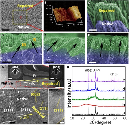
(A) SEM image showing both acid-etched enamel and repaired enamel. (B) A three-dimensional AFM image of repaired enamel. (C) High-magnification SEM image of the red circle in (A). (D) Cross-sectional view of final repaired enamel, where both enamel rods and inter-rods were repaired. R and IR represent for enamel rod and inter-rod, respectively. (E and F) Enamel rods with different orientations can be repaired. (G) TEM image of a longitudinal section of the reconstructed layer on natural enamel, including the native and repaired zones. Inset: SAED of the native enamel (selected area, white cycle) and repaired enamel (selected area, yellow cycle) demonstrated that their long axes correspond to the crystallographic c axis of the HAP. A Pt layer was sputtered to protect the enamel surface from ion beam damage during the milling processes. Lattice fringes of a single enamel rod developed from the native area to the repaired area: The regenerated region (J) had the same characteristics as the natural region (H), and there was no boundary between them (I), demonstrating structural continuity. (K) The XRD spectra indicate the evolution process from CPICs to HAP on the enamel window: the etched enamel (line a), the initial gel-like CPICs coated on the enamel (line b; air-dried for 5 min), the ACP layer resulting from the CPICs (line c; air-dried for 15 min), an intermediate state of the evolution from ACP to HAP (line d; remineralization for 24 hours), and the final crystalline HAP layer on the enamel (line e; remineralization for 48 hours). Scale bars, 20 μm (A), 2 μm (C to F), 500 nm (G), 5 nm (H to J), and 2 nm−1 (G, insets).
The repair of whole tooth enamel could be achieved by this biomimetic tactic. For comparison, we symmetrically divided an etched whole tooth enamel into two parts (Fig. 4, A to C): The left side was protected by nail varnish as the control, and the right side was used for the repair treatment with CPICs. Calcein, a molecule with green fluorescence under ultraviolet (UV) irradiation, was used to label the newly grown HAP. We validated the large-scale enamel repair by confocal laser scanning microscopy (CLSM) and SEM at multiple scales on a cross section of the tooth enamel (Fig. 4, D and F), which showed that the thickness of the repaired layer could reach ~2.7 μm (Fig. 4E). Moreover, SEM at higher magnification confirmed that the HAP crystals grown in the repaired layer shared the notable structure and orientation of the natural enamel.
Fig. 4. Repair of whole tooth enamel and its mechanical and microtribological properties.
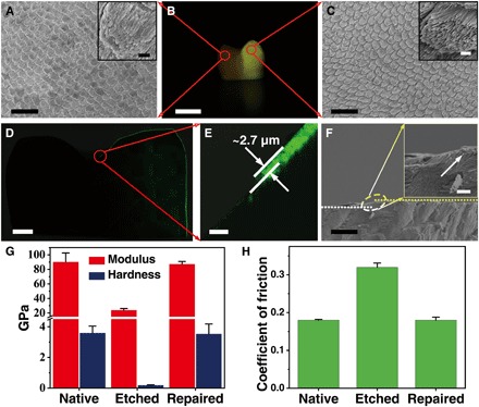
(A) SEM image of native acid-etched enamel. Inset: High-magnification SEM image of acid-etched enamel. (B) Digital image of a whole tooth, in which the left area was covered with acid-resistant varnish (displayed as dark) and the right area was repaired with CPICs containing calcein (displayed as yellow). (C) SEM image of repaired enamel. Inset: High-magnification SEM image of repaired enamel. (D and E) CLSM images of cross sections of the whole tooth. The repaired layer was labeled with calcein, which emitted green fluorescence. The thickness of the repaired layer was approximately 2.7 μm. (F) Cross-sectional view of the SEM image of the repaired enamel on a large scale. Inset: The transition zone from the native to repaired enamel. (G) Calculated hardness and elastic modulus of the enamel samples. (H) Coefficient of friction of the enamel samples measured at a constant normal force of 500 mN. Scale bars, 20 μm (A and C), 5 mm (B), 1 mm (D), 10 μm (E and F), 1 μm (A, inset, and C, inset), and 2 μm (F, inset).
Evaluation of mechanical strength
The mechanical properties and microtribological behavior are essential in an enamel repair evaluation and are examined by nanoindentation tests (2, 38). According to the established method (39), the hardness (H) and elastic modulus (E) can be calculated by using load-displacement curves (fig. S8A). The native enamel had optimal mechanical performance characteristics, with an H of 3.19 ± 0.05 GPa (means ± SD) and an E of 84.55 ± 12.38 GPa (Fig. 4G). However, the mechanical properties of the enamel were dramatically weakened by phosphoric acid etching (37 wt % for 30 s). The CPIC-caused epitaxial growth recovered the enamel strength, with H and E values of 3.84 ± 0.20 GPa and 87.26 ± 3.73 GPa, respectively (Fig. 4G). The coefficient of friction (COF) is an important microtribological index of enamel. The wear resistance of enamel increases with the decreasing COF. In comparison with the high COF (0.32 ± 0.011) of etched enamel, the low COF (0.18 ± 0.008) of the CPIC-repaired enamel was similar to that of native enamel (0.18 ± 0.002), indicating superior antiwear properties after repair (Fig. 4H). These properties should be attributed to the structural continuity between the grown layer and native area resulting from the epitaxial construction. After repair, the mechanical strengths were slightly enhanced, which could be explained by the higher quality of the artificially regrown HAP, which contained less carbonate content than the native one (fig. S9) (40–42). This improvement can also be used to confirm the successful epitaxial growth of artificial HAP on the native enamel rods. In contrast, by using conventional ACP as the repair material, although the H and E values were partially improved (fig. S8B), the COF stayed at a relatively high value of 0.24 ± 0.018 (fig. S8C) because of the poor combination between the repaired layer and the native enamel. This difference reflects a unique advantage of the biomimetic crystalline-amorphous mineralization frontier in the enamel repair.
DISCUSSION
Although a range of materials, such as composite resins, ceramics, and amalgam (43), have been developed for the restoration of tooth enamel, they have failed to achieve permanent repair because of the imperfect combination between these foreign materials and the native enamel (44). However, the HAP layer newly regrown by epitaxial remineralization can be integrated into native enamel such that the repair would be permanent, and this process may be developed as an effective cure for enamel erosion in clinical practice.
There may be a concern about the toxicity of the organic stabilizer, TEA, in the enamel repair. TEA has been widely used in the pharmaceutical industry, and according to the International Council for Harmonisation, Q3C (R6), the permitted daily exposure of TEA is 62.5 mg/day and is placed in class 3 (45). In our enamel repair experiment, we used 1 ml of CPIC ethanol solution (2 mg/ml) for the treatment, and the total TEA amount is only ~27.6 mg. It has been demonstrated experimentally that the TEA can be removed completely with ethanol evaporation so that there is no residual TEA in the repaired layer. Another concern is the thin repair layer because ~2.8 μm is the distance limitation for the epitaxial growth of enamel in the ACP layer at present. This limitation may be attributed to competition between the biomimetic crystallization frontier movement rate and the lifetime of the ACP (46). Theoretically, we suggest that this thickness can be improved by either increasing directional crystallization or enhancing ACP stability. Experimentally, we show that a cyclic treatment by using our current method can readily thicken the repaired layer (fig. S10). Therefore, we believe that TEA-stabilized CPICs will be developed as a promising enamel repair material for dental applications in the future.
The key to ideal enamel repair is the precise duplication of its hierarchical and complicated structure; furthermore, a fundamental challenge in bioinspired material syntheses is the discovery of an effective approach for copying complicated structures in natural materials to a wide range of artificial ones (47). Our biomimetic tactic for enamel regeneration can be extended as a general strategy for the construction of materials with structural complexity by establishing a biomimetic mineralization frontier for continuous and epitaxial construction, in which the ion clusters act as the basic building blocks. This achievement not only deepens our understanding of biomineralization but also provides a new pathway for bioinspired design and production.
MATERIALS AND METHODS
Consumables
Unless otherwise specified, the following chemicals were used without further purification: calcium chloride dihydrate (CaCl2·2H2O; 99.0%), sodium azide (Na3N; 99%), acetone [(CH3)2CO; American Chemical Society (ACS) reagent, 99.5%], dimethyl sulfoxide–d6 [DMSO-d6; (CD3)2SO; 99.96 atomic % D] (Sigma-Aldrich); TEA [(C2H5)3N; 99.5%], phosphoric acid (H3PO4; 85% in H2O solution), ethanol (C2H5OH; 99.7%), disodium hydrogen phosphate (Na2HPO4; 99.99%), potassium phosphate dibasic anhydrous (K2HPO4; 99.99%), sodium fluoride (NaF; ACS reagent, 99%,), potassium chloride (KCl; Analytical reagent, 99.5%), Hepes (C8H18N2OS; 99%), thymol (C10H14O; ACS reagent, 98%), and potassium bromide (KBr; spectrographic grade, 99.5%) (Aladdin). Nail varnish was obtained from Sephora. Deionized water was used in the experiment, and all solutions were filtered through 0.22-μm Millipore films before use.
Noncarious human third molars were provided by the Affiliated Hospital of Stomatology of Zhejiang University School of Medicine in this study. The use of human tooth tissue specimens followed a protocol that was approved by the ethical committee of the hospital and Zhejiang University and agreed upon by the patients. Enamel windows (4 mm by 5 mm) were cut by a slow-speed diamond saw cooled by water. Samples were cleaned by ultrasonic treatment in deionized water for 20 min after polishing with silicon carbide paper (nos. 600 and 1200) and stored in thymol solution (0.2 wt %) at 4°C before use.
CPIC preparation
CPICs were synthesized in our laboratory as follows: (i) For the preparation of solution A, 0.20 g of CaCl2·2H2O and 3.8 ml of TEA were added into 80 ml of ethanol and then ultrasonicated for 5 min. (ii) For the preparation of solution B, 70 μl of H3PO4 was added into 20 ml of ethanol and stirred thoroughly. Solution B was dropped into solution A with slight agitation, and then CPICs (2 mg/ml) formed in the solution. The gel-like CPICs were collected through centrifugation [30,427 relative centrifugal force (Rcf)] and washed twice with ethanol.
ACP nanoparticle preparation
The conventional ACP material was prepared by the method suggested by Nancollas and Mohan (48). The ACP nanoparticles were synthesized at room temperature. A 100-ml Na2HPO4 (4 × 10⁻³ M; pH = 9.5 ± 0.1) solution was quickly added to a 100-ml CaCl2 (6 × 10⁻³ M; pH = 9.5 ± 0.1) solution and allowed to react for 1 min. The precipitate was separated by centrifugation (13,523 Rcf) and washed three times with acetone. All solids were dried under vacuum at 37°C. For the following experiments, ACP ethanol solution (2 mg/ml) was prepared.
HAP rod preparation
The HAP rods (the mineral phase was confirmed by XRD; see fig. S5C) were prepared using a solvothermal method. The as-prepared CPIC ethanol solution was transferred to a Teflon autoclave, which was sealed and heated to 180°C for 8 hours. After cooling to room temperature, the product was separated by centrifugation at 13,523 Rcf and then washed with deionized water and ethanol three times and dried under vacuum at 37°C for 24 hours.
Bulk ACP preparation
The bulk ACP was fabricated by dropping a CPIC ethanol solution (100 μl; 2 mg/ml) or ACP nanoparticle ethanol solution (100 μl; 2 mg/ml) onto a glass substrate, and the resulting samples were air-dried for 15 min at room temperature.
Epitaxial growth of HAP using CPICs
The as-prepared HAP rods (1 mg) were dispersed in ethanol solution (2 ml). This solution (10 μl) was dropped onto a marked TEM grid, and then the HAP rods were loaded on a TEM grid and the position of the HAP rods was recorded. The HAP-loaded grid was partially dipped into a CPIC ethanol solution (2 mg/ml) for 30 s and then withdrawn. After being air-dried at room temperature, these samples were successively examined by using HRTEM and EDXS. The ACP-coated HAP was kept in a sealed Petri dish to which droplets of deionized water were added to ensure a humid environment for the phase transformation from ACP to HAP. The total duration of the crystallization procedure was 30 min at 37°C. As the control group, half of the grid containing HAP rods was dipped into the conventional ACP ethanol solution (2 mg/ml), withdrawn, and air-dried at room temperature. These samples were characterized periodically by using HRTEM.
Tooth enamel repair
Etching treatment of enamel
To simulate early caries lesions, tooth enamel windows were etched with H3PO4 (37 wt %) for 30 s. To both simulate early caries lesions and remove the prism-less enamel of the outermost tooth surface (49), the whole tooth samples were etched with H3PO4 (37 wt %) for 10 min. All of the samples were ultrasonicated in deionized water for 20 min to ensure the removal of any residual contaminants and air-dried.
Enamel repair using CPICs
For comparison, half of the enamel surface was covered with acid-resistant nail varnish, and the remaining area was used for repair by using CPICs. The CPIC ethanol solution (100 μl; 2 mg/ml) was dropped onto the enamel surface. Subsequently, the samples were air-dried at 25°C for 5 min, resulting in the formation of a gel-like CPIC-coated layer on the enamel; at 15 min, the CPIC layer spontaneously turned into an ACP layer. Then, the enamel windows were immersed into modified simulated oral fluid (m-SOF; 10 ml per sample; containing 1.5 mM CaCl2, 0.9 mM K2HPO4, 15 ppm F−1, 130 mM KCl, 1 mM NaN3, and 20 mM Hepes buffer) at pH 7.00 ± 0.03 at 37°C for the designated time. The total duration of the incubation process was 48 hours, which was a sufficient time period that allowed full crystallization of the amorphous phase. To increase the thickness of the repaired layer, the above-mentioned CPIC treatment on enamel was applied repeatedly to establish the layer-by-layer repair. After incubation, the repaired enamel windows were sonicated in water for 20 min, rinsed with water, and air-dried at 25°C before examination.
Enamel repair using ACP
An ACP nanoparticle ethanol solution (100 μl; 2 mg/ml) was dropped onto the acid-etched enamel window, and the sample was air-dried for 15 min at 25°C and a relative humidity of 60%. Then, the windows were immersed in m-SOF (10 ml per sample) at pH 7.00 ± 0.03 at 37°C for 48 hours to ensure maturation. After incubation, the repaired enamel windows were sonicated in water for 20 min, rinsed with water, and air-dried at 25°C before examination.
Repair of whole tooth enamel using CPICs
For the purpose of comparison, half of a tooth surface was covered with acid-resistant nail varnish as the control zone, and the remaining was left as an experimental zone for repair by using CPICs. A CPIC ethanol solution (1 ml; 2 mg/ml) or calcein (1 μM)–containing CPIC ethanol solution (1 ml; 2 mg/ml) was dropped onto the whole tooth enamel surface. Then, all of the samples were immersed in m-SOF (50 ml per sample) at pH 7.00 ± 0.03 at 37°C for 48 hours to ensure maturation. After incubation, the whole teeth were sonicated in deionized water for 20 min, rinsed with water, and air-dried before examination. To obtain a clear fluorescence picture of the whole tooth, we rinsed the varnish using acetone three times and took a photograph through an optical filter under UV light with a light intensity of 1200 mW/cm2 (±10%) and a utilizable wavelength range of 430 to 480 nm.
Focused ion beam preparation of samples for TEM observation
Ultrathin sections of the repaired enamel for TEM characterization of the structure and crystallography were prepared with a dual-beam focused ion beam (FIB)–scanning electron microscope instrument (Quanta 3D FEG, FEI, USA), which was fitted with a liquid gallium ion source. A layer of platinum (thickness, ~1 μm) was deposited over a region of interest to protect the surface from ion beam damage during the milling processes. The thin sections were lifted out and transferred onto a copper grid for further TEM and SAED observations.
Characterization
Dynamic light scattering
The size distribution of CPICs in ethanol solution was determined at 25°C by a Zetasizer Nano S (ZEN 3600, Malvern, England).
NMR spectroscopy
Four samples were prepared as follows: H3PO4 (7 μl) was added to ethanol (10 ml); CaCl2·2H2O (0.02 g) and TEA (0.38 ml) were added to ethanol (10 ml); H3PO4 (7 μl) and TEA (0.38 ml) were added to ethanol (10 ml); and the CPIC ethanol solution (10 ml; 2 mg/ml) was centrifuged at 30,427 Rcf and redispersed in ethanol (10 ml). Each sample (0.4 ml) was added to an NMR tube containing DMSO-d6 sealed in a capillary tube as a deuterated solvent and immediately characterized by 1H and 31P DirectDrive2 600 MHz NMR spectrometer (Agilent Technologies Inc., USA).
FTIR spectroscopy
The gel-like CPICs and TEA [3.8% (v/v) in ethanol] were sealed between two KBr plates for characterization. The CPIC-induced bulk ACP was thoroughly blended with KBr powder to prepare a pellet. FTIR (IRAffinity-1, Shimadzu, Japan) was performed with 30 scans at 4 cm−1 resolution from 4000 to 400 cm−1. The background was determined using blank KBr plates.
Gas chromatography–mass spectrometry
CPIC-induced ACP (0.020 g) was dissolved by adding a definite volume of 5 M HCl and then adding a definite volume of methanol making a total volume of 5 ml. A stock standard solution (10 mg/ml) was prepared by dissolving 0.100 g of TEA into 10 ml of methanol solution, and a working standard solution was obtained by dilution. GC-MS analysis was performed on a Shimadzu GCMS-QP2010 system (Japan) using a DB-5ms capillary column (30 m by 0.25 mm; film thickness, 0.25 μm).
X-ray diffraction
The as-prepared samples were measured by using XRD (X’Pert3 Powder, Malvern Panalytical, Netherlands) with Cu Kα radiation (λ = 0.1542 nm) operating at an acceleration voltage of 40 kV and a current of 40 mA. The diffraction intensity data were scanned with a sampling step of 0.02° in the 2θ range from 10° to 70°.
Transmission electron microscopy
TEM was performed with a Hitachi HT-7700 (Japan) operating at 120 kV. HRTEM was carried out on an FEI Tecnai G2 F20 microscope (USA) or a JEOL JEM-2100F microscope (Japan), and both were operated at 200 kV. EDXS spectra were collected using JEM-2100F equipped with an energy dispersive x-ray spectrometer (Oxford-T80, NanoLab Technologies Inc., USA).
Scanning electron microscopy
SEM images were acquired by using a Hitachi SU8010 scanning electron microscope (Japan). Specimens were mounted on an aluminum stage with a carbon tape. The tooth surfaces were sputtered with Pt and observed under an accelerating voltage of 5 kV. Both top-down and side views of the sectioned tooth samples were observed using SEM. EDXS spectra were collected using SU8010 equipped with an energy dispersive x-ray spectrometer (Model 550i, IXRF Systems).
Atomic force microscopy
AFM images of enamel specimens and CPIC-induced bulk ACP were collected under ambient conditions (temperature, 25°C; relative humidity, 40%) by using a multimode atomic force microscope (NanoScope IVa, Veeco, USA) in tapping mode. All images were analyzed with an image analysis software (NanoScope Analysis version 1.7).
Confocal laser scanning microscopy
The samples were prepared by cutting repaired whole teeth along the longitudinal direction. The repaired layer of the whole tooth was labeled with calcein. Fluorescence images were obtained using an inverted confocal laser scanning microscope (IX81-FV1000, Olympus, Japan). Specimens were illuminated with a 488-nm laser. All images were captured and analyzed with an image analysis software (Olympus FluoView version 4.1 viewer).
Nanoindentation
Nanoindentation testing was carried out in a nanoindenter (G200, Agilent Technologies, CA, USA) with a Berkovich tip (tip radius of approximately 20 nm). Native enamel and acid-etched enamel were used as controls. Each sample was stored, and the data were obtained at 25°C and a relative humidity of 40%. For the test, the tip was calibrated with fused silica before evaluation. The hardness and elastic modulus of the specimens were measured using a continuous stiffness measurement technique. During the loading process, the constant strain rates were controlled at 0.2 nm s−1. The applied load force and the depth of penetration into the samples during the indentation were continuously monitored by the computer. Twenty points were indented for each specimen, and three different specimens of native enamel, acid-etched enamel, and repaired enamel were tested. The data were recorded and processed by TestWorks 4 software (MTS Systems Corporation, Eden Prairie, MN, USA), which obtained the nanohardness and elastic modulus by calculating the mean value from 200 nm to 2000 nm, and these data were presented as force-displacement curves.
Microscratch tests
Microscratch tests of sound enamel, acid-etched enamel, and repaired enamel were performed using a microscratch tester (UNHT/MCT/MST, Anton Paar GmbH, Austria). A Rockwell diamond tip with a radius of 20 μm was used for all tests. All scratch testing of the samples were conducted at a constant normal load of 500 mN with a velocity of 200 μm/min. The scratch distance was 200 μm. At least three scratches were made in each test region. Each scratch was at least 50 μm away from the next scratch.
Supplementary Material
Acknowledgments
We thank F. Chen, Y. Qiu, and W. Yin for their assistance with SEM, AFM, and CLSM; R. Hong and C. Jin for the technical assistance and valuable discussions. Funding: This study was supported by the National Key Research and Development Program of China (2018YFC1105101), the National Natural Science Foundation of China (21625105 and 21805241), and the China Postdoctoral Science Foundation (2017M621909 and 2018T110585). Author contributions: R.T., Z.L., and C.S. initiated the study. R.T. and Z.L. supervised and supported the project. C.S. carried out the enamel repair and most of the characterizations. B.J. performed the HRTEM examination. Z.M. prepared the CPIC materials. Y. Zhao and L.Y. performed the nanoindentation tests. Z.W. and Y. Zhou treated the enamel samples. H.L. and Z.Z. conducted the FIB preparation. C.S., H.P., Z.L., and R.T. analyzed the data. C.S., Z.L., and R.T. wrote the manuscript. All authors reviewed and approved the manuscript. Competing interests: The authors declare that they have no competing interests. Data and materials availability: All data needed to evaluate the conclusions in the paper are present in the paper and/or the Supplementary Materials. Additional data related to this paper may be requested from the authors.
SUPPLEMENTARY MATERIALS
Supplementary material for this article is available at http://advances.sciencemag.org/cgi/content/full/5/8/eaaw9569/DC1
Fig. S1. Size distribution of CPICs and their stability in ethanol solution.
Fig. S2. Characterization of TEA in CPICs and resulting ACP.
Fig. S3. Characterization of the conventional ACP nanoparticles and their aggregates.
Fig. S4. Examination of the CPIC-induced bulk ACP by AFM.
Fig. S5. Characterization of the synthetic HAP.
Fig. S6. HRTEM images of the structural gap resulting in the particle attachment of ACP onto HAP.
Fig. S7. Enamel repair using the conventional ACP nanoparticles.
Fig. S8. Mechanical examinations of the ACP-repaired enamel.
Fig. S9. SEM-EDXS analysis of the native enamel and the repaired layer.
Fig. S10. Thickening the repaired enamel layer using the cyclic treatments.
REFERENCES AND NOTES
- 1.Eder M., Amini S., Fratzl P., Biological composites—Complex structures for functional diversity. Science 362, 543–547 (2018). [DOI] [PubMed] [Google Scholar]
- 2.Lawn B. R., Lee J. J.-W., Chai H., Teeth: Among nature’s most durable biocomposites. Annu. Rev. Mat. Res. 40, 55–75 (2010). [Google Scholar]
- 3.A. Nanci, Ten Cate’s Oral Histology: Development, Structure, and Function (C. V. Mosby, ed. 8, 2012). [Google Scholar]
- 4.Bowes J. H., Murray M. M., The chemical composition of teeth: The composition of human enamel and dentine. Biochem. J. 29, 2721–2727 (1935). [DOI] [PMC free article] [PubMed] [Google Scholar]
- 5.An B. B., Wang R. R., Zhang D. S., Role of crystal arrangement on the mechanical performance of enamel. Acta Biomater. 8, 3784–3793 (2012). [DOI] [PubMed] [Google Scholar]
- 6.He L. H., Swain M. V., Understanding the mechanical behaviour of human enamel from its structural and compositional characteristics. J. Mech. Behav. Biomed. Mater. 1, 18–29 (2008). [DOI] [PubMed] [Google Scholar]
- 7.Cao Y., Mei M. L., Li Q. L., Lo E. C. M., Chu C. H., Agarose hydrogel biomimetic mineralization model for the regeneration of enamel prismlike tissue. ACS Appl. Mater. Interfaces 6, 410–420 (2013). [DOI] [PubMed] [Google Scholar]
- 8.Li L., Pan H., Tao J., Xu X., Mao C., Gu X., Tang R., Repair of enamel by using hydroxyapatite nanoparticles as the building blocks. J. Mater. Chem. 18, 4079–4084 (2008). [Google Scholar]
- 9.Yamagishi K., Onuma K., Suzuki T., Okada F., Tagami J., Otsuki M., Senawangse P., Materials chemistry: A synthetic enamel for rapid tooth repair. Nature 433, 819–819 (2005). [DOI] [PubMed] [Google Scholar]
- 10.Wald T., Spoutil F., Osickova A., Prochazkova M., Benada O., Kasparek P., Bumba L., Klein O. D., Sedlacek R., Sebo P., Prochazka J., Osicka R., Intrinsically disordered proteins drive enamel formation via an evolutionarily conserved self-assembly motif. Proc. Natl. Acad. Sci. U.S.A. 114, E1641–E1650 (2017). [DOI] [PMC free article] [PubMed] [Google Scholar]
- 11.Palmer L. C., Newcomb C. J., Kaltz S. R., Spoerke E. D., Stupp S. I., Biomimetic systems for hydroxyapatite mineralization inspired by bone and enamel. Chem. Rev. 108, 4754–4783 (2008). [DOI] [PMC free article] [PubMed] [Google Scholar]
- 12.Selwitz R. H., Ismail A. I., Pitts N. B., Dental caries. Lancet 369, 51–59 (2007). [DOI] [PubMed] [Google Scholar]
- 13.Xie R., Feng Z., Li S., Xu B., EDTA-assisted self-assembly of fluoride-substituted hydroxyapatite coating on enamel substrate. Cryst. Growth Des. 11, 5206–5214 (2011). [Google Scholar]
- 14.Wang Y., Lin K., Wu C., Liu X., Chang J., Preparation of hierarchical enamel-like structures from nano- to macro-scale, regulated by inorganic templates derived from enamel. J. Mater. Chem. B 3, 65–71 (2015). [DOI] [PubMed] [Google Scholar]
- 15.Mukherjee K., Ruan Q., Nutt S., Tao J., De Yoreo J. J., Moradian-Oldak J., Peptide-based bioinspired approach to regrowing multilayered aprismatic enamel. ACS Omega 3, 2546–2557 (2018). [DOI] [PMC free article] [PubMed] [Google Scholar]
- 16.Yang Y., Lv X. P., Shi W., Li J. Y., Li D. X., Zhou X. D., Zhang L. L., 8DSS-promoted remineralization of initial enamel caries in vitro. J. Dent. Res. 93, 520–524 (2014). [DOI] [PubMed] [Google Scholar]
- 17.Fan Y., Sun Z., Moradian-Oldak J., Controlled remineralization of enamel in the presence of amelogenin and fluoride. Biomaterials 30, 478–483 (2009). [DOI] [PMC free article] [PubMed] [Google Scholar]
- 18.Ruan Q., Siddiqah N., Li X., Nutt S., Moradian-Oldak J., Amelogenin-chitosan matrix for human enamel regrowth: Effects of viscosity and supersaturation degree. Connect. Tissue Res. 55 ( suppl. 1), 150–154 (2014). [DOI] [PMC free article] [PubMed] [Google Scholar]
- 19.Busch S., Regeneration of human tooth enamel. Angew. Chem. Int. Ed. 43, 1428–1431 (2004). [DOI] [PubMed] [Google Scholar]
- 20.Li L., Mao C. Y., Wang J. M., Xu X. R., Pan H. H., Deng Y., Gu X. H., Tang R. K., Bio-inspired enamel repair via Glu-directed assembly of apatite nanoparticles: An approach to biomaterials with optimal characteristics. Adv. Mater. 23, 4695–4701 (2011). [DOI] [PubMed] [Google Scholar]
- 21.Marie B., Joubert C., Tayalé A., Zanella-Cléon I., Belliard C., Piquemal D., Cochennec-Laureau N., Marin F., Gueguen Y., Montagnani C., Different secretory repertoires control the biomineralization processes of prism and nacre deposition of the pearl oyster shell. Proc. Natl. Acad. Sci. U.S.A. 109, 20986–20991 (2012). [DOI] [PMC free article] [PubMed] [Google Scholar]
- 22.Mahamid J., Sharir A., Addadi L., Weiner S., Amorphous calcium phosphate is a major component of the forming fin bones of zebrafish: Indications for an amorphous precursor phase. Proc. Natl. Acad. Sci. U.S.A. 105, 12748–12753 (2008). [DOI] [PMC free article] [PubMed] [Google Scholar]
- 23.Nassif N., Pinna N., Gehrke N., Antonietti M., Jäger C., Cölfen H., Amorphous layer around aragonite platelets in nacre. Proc. Natl. Acad. Sci. U.S.A. 102, 12653–12655 (2005). [DOI] [PMC free article] [PubMed] [Google Scholar]
- 24.DeVol R. T., Sun C.-Y., Marcus M. A., Coppersmith S. N., Myneni S. C. B., Gilbert P. U. P. A., Nanoscale transforming mineral phases in fresh nacre. J. Am. Chem. Soc. 137, 13325–13333 (2015). [DOI] [PubMed] [Google Scholar]
- 25.Mass T., Giuffre A. J., Sun C.-Y., Stifler C. A., Frazier M. J., Neder M., Tamura N., Stan C. V., Marcus M. A., Gilbert P. U. P. A., Amorphous calcium carbonate particles form coral skeletons. Proc. Natl. Acad. Sci. U.S.A. 114, E7670–E7678 (2017). [DOI] [PMC free article] [PubMed] [Google Scholar]
- 26.Perez A., Melinon P., Dupuis V., Jensen P., Prevel B., Tuaillon J., Bardotti L., Martet C., Treilleux M., Broyer M., Pellarin M., Vaille J. L., Palpant B., Lerme J., Cluster assembled materials: A novel class of nanostructured solids with original structures and properties. J. Phys. D Appl. Phys. 30, 709–721 (1997). [Google Scholar]
- 27.Posner A. S., Betts F., Synthetic amorphous calcium phosphate and its relation to bone mineral structure. Acc. Chem. Res. 8, 273–281 (1975). [Google Scholar]
- 28.Habraken W. J., Tao J., Brylka L. J., Friedrich H., Bertinetti L., Schenk A. S., Verch A., Dmitrovic V., Bomans P. H. H., Frederik P. M., Laven J., van der Schoot P., Aichmayer B., de With G., DeYoreo J. J., Sommerdijk N. A. J. M., Ion-association complexes unite classical and non-classical theories for the biomimetic nucleation of calcium phosphate. Nat. Commun. 4, 1507 (2013). [DOI] [PubMed] [Google Scholar]
- 29.Onuma K., Ito A., Cluster growth model for hydroxyapatite. Chem. Mater. 10, 3346–3351 (1998). [Google Scholar]
- 30.Gebauer D., Völkel A., Cölfen H., Stable prenucleation calcium carbonate clusters. Science 322, 1819–1822 (2008). [DOI] [PubMed] [Google Scholar]
- 31.Olszta M. J., Cheng X., Jee S. S., Kumar R., Kim Y.-Y., Kaufman M. J., Douglas E. P., Gower L. B., Bone structure and formation: A new perspective. Mater. Sci. Eng. R Rep. 58, 77–116 (2007). [Google Scholar]
- 32.Sun S. T., Gebauer D., Cölfen H., A general strategy for colloidal stable ultrasmall amorphous mineral clusters in organic solvents. Chem. Sci. 8, 1400–1405 (2017). [DOI] [PMC free article] [PubMed] [Google Scholar]
- 33.Beniash E., Metzler R. A., Lam R. S., Gilbert P., Transient amorphous calcium phosphate in forming enamel. J. Struct. Biol. 166, 133–143 (2009). [DOI] [PMC free article] [PubMed] [Google Scholar]
- 34.De Yoreo J. J., Gilbert P. U., Sommerdijk N. A., Penn R. L., Whitelam S., Joester D., Zhang H., Rimer J. D., Navrotsky A., Banfield J. F., Wallace A. F., Michel F. M., Meldrum F. C., Cölfen H., Dove P. M., Crystallization by particle attachment in synthetic, biogenic, and geologic environments. Science 349, aaa6760 (2015). [DOI] [PubMed] [Google Scholar]
- 35.Weiner S., Lowenstam H., Organization of extracellularly mineralized tissues: A comparative study of biological crystal growt. CRC Crit. Rev. Biochem. 20, 365–408 (1986). [DOI] [PubMed] [Google Scholar]
- 36.Cui F. Z., Ge J., New observations of the hierarchical structure of human enamel, from nanoscale to microscale. J. Tissue Eng. Regen. Med. 1, 185–191 (2007). [DOI] [PubMed] [Google Scholar]
- 37.White S. N., Luo W., Paine M. L., Fong H., Sarikaya M., Snead M. L., Biological organization of hydroxyapatite crystallites into a fibrous continuum toughens and controls anisotropy in human enamel. J. Dent. Res. 80, 321–326 (2001). [DOI] [PubMed] [Google Scholar]
- 38.Ebenstein D. M., Pruitt L. A., Nanoindentation of biological materials. Nano Today 1, 26–33 (2006). [Google Scholar]
- 39.Oliver W. C., Pharr G. M., An improved technique for determining hardness and elastic modulus using load and displacement sensing indentation experiments. J. Mater. Res. 7, 1564–1583 (1992). [Google Scholar]
- 40.Legfros R. Z., Sakae T., Bautista C., Retino M., Legeros J. P., Magnesium and carbonate in enamel and synthetic apatites. Adv. Dent. Res. 10, 225–231 (1996). [DOI] [PubMed] [Google Scholar]
- 41.Teraoka K., Ito A., Maekawa K., Onuma K., Tateishi T., Tsutsumi S., Mechanical properties of hydroxyapatite and OH-carbonated hydroxyapatite single crystals. J. Dent. Res. 77, 1560–1568 (1998). [DOI] [PubMed] [Google Scholar]
- 42.Habelitz S., Marshall S. J., Marshall G. W. Jr., Balooch M., Mechanical properties of human dental enamel on the nanometre scale. Arch. Oral Biol. 46, 173–183 (2001). [DOI] [PubMed] [Google Scholar]
- 43.W. J. O’Brien, Dental Materials and Their Selection (Quintessence Publisihing Co., ed. 4, 2009). [Google Scholar]
- 44.Ferracane J. L., Hilton T. J., Polymerization stress—Is it clinically meaningful? Dent. Mater. 32, 1–10 (2016). [DOI] [PubMed] [Google Scholar]
- 45.ICH, Impurities: Guideline for residual solvents Q3C (R6), in Proceedings of the International Conference on Harmonization, Geneva, September 2016. [Google Scholar]
- 46.Jiang S., Pan H., Chen Y., Xu X., Tang R., Amorphous calcium phosphate phase-mediated crystal nucleation kinetics and pathway. Faraday Discuss. 179, 451–461 (2015). [DOI] [PubMed] [Google Scholar]
- 47.Wegst U. G. K., Bai H., Saiz E., Tomsia A. P., Ritchie R. O., Bioinspired structural materials. Nat. Mater. 14, 23–36 (2014). [DOI] [PubMed] [Google Scholar]
- 48.Nancollas G. H., Mohan M. S., The growth of hydroxyapatite crystals. Arch. Oral Biol. 15, 731–745 (1970). [DOI] [PubMed] [Google Scholar]
- 49.Gwinnett A. J., Histology of normal enamel. III. Phase contrast study. J. Dent. Res. 45, 865–869 (1966). [DOI] [PubMed] [Google Scholar]
- 50.Stutman J. M., Termine J. D., Posner A. S., Vibrational spectra and structure of the phosphate ion in some calcium phosphates. Trans. N. Y. Acad. Sci. 27, 669–675 (1965). [DOI] [PubMed] [Google Scholar]
- 51.Eanes E. D., Gillessen I. H., Posner A. S., Intermediate states in the precipitation of hydroxyapatite. Nature 208, 365–367 (1965). [DOI] [PubMed] [Google Scholar]
Associated Data
This section collects any data citations, data availability statements, or supplementary materials included in this article.
Supplementary Materials
Supplementary material for this article is available at http://advances.sciencemag.org/cgi/content/full/5/8/eaaw9569/DC1
Fig. S1. Size distribution of CPICs and their stability in ethanol solution.
Fig. S2. Characterization of TEA in CPICs and resulting ACP.
Fig. S3. Characterization of the conventional ACP nanoparticles and their aggregates.
Fig. S4. Examination of the CPIC-induced bulk ACP by AFM.
Fig. S5. Characterization of the synthetic HAP.
Fig. S6. HRTEM images of the structural gap resulting in the particle attachment of ACP onto HAP.
Fig. S7. Enamel repair using the conventional ACP nanoparticles.
Fig. S8. Mechanical examinations of the ACP-repaired enamel.
Fig. S9. SEM-EDXS analysis of the native enamel and the repaired layer.
Fig. S10. Thickening the repaired enamel layer using the cyclic treatments.