Abstract
Coronary artery obstruction is an uncommon but devastating complication of transcatheter aortic valve replacement (TAVR). Computed tomography appears to be a sensitive but nonspecific predictor of coronary artery obstruction. Transcatheter approaches to prevent and treat coronary artery obstruction, such as “snorkel” stenting, are unsatisfactory because of serious early and late ischemic complications. Bioprosthetic or native aortic scallop intentional laceration to prevent iatrogenic coronary artery obstruction during TAVR (BASILICA) is an early-stage transcatheter procedure to prevent coronary artery obstruction. It works by splitting the native or bioprosthetic leaflets so that they splay after TAVR and preserve coronary artery inflow. Because of the paucity of suitable alternatives, there is interest in the BASILICA technique despite its infancy. This tutorial review summarizes current thinking about how to predict and prevent coronary artery obstruction using BASILICA. First, the authors depict the main pathophysiological mechanisms of TAVR-associated coronary artery obstruction, along with the factors thought to contribute to coronary obstruction. Next, the authors provide a step-by-step guide to analyzing pre-procedural computed tomographic findings to assess obstruction risk and, if desirable, to plan BASILICA. Next, the authors describe the mechanisms underlying transcatheter electrosurgery. Finally, they provide step-by-step guidance on how to perform the procedure, along with a required equipment list.
Keywords: cardiac computed tomography, coronary artery obstruction, transcatheter aortic valve replacement, transcatheter electrosurgery, valve-in-valve, virtual valve, virtual valve-to-coronary distance
Coronary artery obstruction is an uncommon but devastating complication of valve-invalve transcatheter aortic valve replacement (TAVR) (1-5). Coronary artery obstruction occurs when the transcatheter heart valve displaces the underlying surgical or native aortic valve leaflets outward and obstructs the coronary artery ostia, directly or by sequestering the sinus of Valsalva at the sinotubular junction.
Bioprosthetic or native aortic scallop intentional laceration to prevent iatrogenic coronary artery obstruction during TAVR (BASILICA) is a new transcatheter procedure (6) derived from the LAMPOON (intentional laceration of the anterior mitral leaflet to prevent left ventricular outflow obstruction) mitral valve procedure (7). Both entail electrosurgical crossing and laceration of valve leaflets to prevent them from obstructing critical structures during transcatheter valve implantation.
BASILICA remains a work in progress using off-the-shelf tools. It nevertheless appears effective to prevent coronary obstruction in at-risk patients with both bioprosthetic and native aortic valve failure. After an initial compassionate-use case series, we recently completed a systematic investigational device exemption clinical protocol supporting the feasibility of this approach (8). The procedure was successful in 28 of 30 subjects and 35 of 37 leaflets attempted and was associated with no coronary obstruction. There was 1 definite and 2 possible strokes (3.3% to 10%) associated with the BASILICA TAVR investigational device exemption trial.
In this paper, we describe our current approach to identifying and preventing TAVR-induced coronary artery obstruction using the BASILICA technique. However, because BASILICA is a work in progress, we approach the topic with caution and humility, especially regarding our ability to predict coronary obstruction with precision.
TRADITIONAL APPROACHES TO AVOID TAVR-INDUCED CORONARY OBSTRUCTION
The main contemporary approach to avoid TAVR-induced coronary obstruction is careful patient selection using computed tomography (CT). The standard treatment is surgical aortic valve replacement, which may be unsuitable for high-risk patients.
The remaining options for inoperable patients are unattractive. Expectant or palliative management is common. Prophylactic guidewire, catheter, or stent intubation of at-risk coronary arteries has been proposed to allow prompt treatment or prevention of TAVR-associated coronary obstruction (3,4,9). These catheter tools are inevitably pinned between the TAVR implant and the aortic root. Unfortunately, pre-positioned stents are easily entrapped and often must be deployed even if otherwise unnecessary. Rescue percutaneous coronary intervention is often unsuccessful because the pinned valve leaflets may not be traversable. Worse, cyclic compression and other local vascular perturbations around (“snorkel,” “chimney,” or “periscope”) stents lead to frequent stent deformation and thrombosis and serious ischemic complications (4,5). Even repositionable or retrievable TAVR devices (such as the Evolut R [Medtronic, Minneapolis, Minnesota], Lotus [Boston Scientific, Natick, Massachusetts], and Portico [Abbott St. Jude, Santa Clara, California]) can cause delayed coronary obstruction (4,5). Emergency surgery rescue has high mortality for early (2) and delayed (5) coronary obstruction.
These shortcomings led us to develop a transcatheter alternative in BASILICA.
MECHANISMS AND CONTRIBUTORS TO TAVR-INDUCED CORONARY ARTERY OBSTRUCTION
Table 1 and the Central Illustration summarize the mechanisms of TAVR-induced coronary obstruction. Of the 5, only direct and indirect coronary obstruction from deficient or sequestered sinus of Valsalva are amenable to BASILICA, and of these, the deficient sinus is considered higher risk.
TABLE 1.
Mechanisms and Contributors to Transcatheter Aortic Valve Replacement-Induced Ostial Coronary Artery Obstruction
| Mechanism | Description | Amenable to BASILICA |
|---|---|---|
| “Deficient sinus” | Direct coronary obstruction by leaflet when the sinus of Valsalva is obliterated or effaced. | Yes |
| “Sequestered sinus” | Indirect coronary obstruction; leaflet blocks the entire sinus of Valsalva. Rare in native aortic valve disease. | Yes |
| Mass effect | Obstruction of coronary ostium by a leaflet mass, typically calcific nodule. Extrinsic compression by aortic hematoma intramural or extramural |
No |
| TAVR skirt and commissure | Obstruction from fabric skirt or commissural posts on implanted TAVR device. | No |
| Embolization | Dislodgement of thrombotic or degenerative material. | No |
| Stent deformation and thrombosis | “Snorkel” coronary stents implanted to prevent or treat ostial coronary obstruction are subject to extrinsic compression and abnormal flow conditions. | No |
BASILICA = bioprosthetic or native aortic scallop intentional laceration to prevent iatrogenic coronary artery obstruction during TAVR; TAVR = transcatheter aortic valve replacement.
CENTRAL ILLUSTRATION. Mechanisms of Transcatheter Aortic Valve Replacement-Induced Coronary Obstruction and Mitigation by BASILICA.
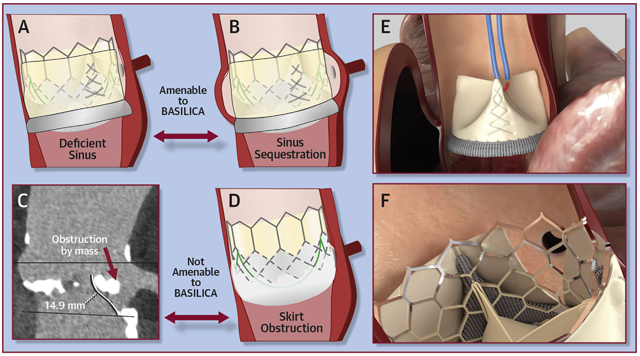
Mechanisms of transcatheter aortic valve replacement (TAVR)–induced coronary obstruction and mitigation by bioprosthetic or native aortic scallop intentional laceration to prevent iatrogenic coronary artery obstruction during TAVR (BASILICA). (A) In a deficient sinus of Valsalva, the outwardly displaced leaflets directly obstruct the coronary artery ostium. (B) In a low sinus of Valsalva and narrow sinotubular junction, the outwardly displaced leaflets indirectly obstruct the coronary artery ostium by sequestering the sinus. (C) A bulky leaflet mass can directly obstruct the coronary ostium. (D) In a low coronary ostium, the fabric-covered frame or skirt can directly obstruct the coronary artery ostium. (E) An electrified BASILICA guidewire lacerates the prior aortic valve leaflets. (F) A TAVR implant splays the lacerated leaflets and ensures inflow to the threatened coronary ostium after BASILICA.
Table 2 summarizes factors contributing to the risk for obstruction. This qualitative approach still fails to predict with certainty which patients will not tolerate TAVR without BASILICA.
TABLE 2.
Factors Contributing to Coronary Obstruction Risk
| Leaflet characteristics |
|
| Sinus of Valsalva factors | |
| Bioprosthetic valve factors |
|
| Transcatheter valve factors |
|
TAVR = transcatheter aortic valve replacement.
USING CT TO PREDICT CORONARY OBSTRUCTION AND PLAN BASILICA
The user-selected annular plane determines most other measurements used to predict obstruction risk and therefore is the key step in BASILICA planning. Table 3 (Figures 1 to 6, Online Figures 1 to 5) summarizes the elements of a BASILICA CT plan, building on the work of Blanke et al. (10) for valve-in-valve TAVR planning. The same technique applies both to native and valve-in-valve planning.
TABLE 3.
Steps to Plan BASILICA on a Computed Tomographic Scan
| Step | Figure |
|---|---|
| 1. Define the exact annular plane. | Figure 1 |
| 2. Measure coronary artery heights, STJ height, and sinus of Valsalva diameters. | Online Figure 1 |
| 3. Do leaflet tips extend beyond coronary ostia or STJ? | Online Figure 2 |
| 4. Select the outer diameter(s) of the intended TAVR device. | Figure 2 |
| 5. Simulate a “virtual valve” implantation using a simple cylinder to model the TAVR implant. Position it at the annular center, and rotate as needed to conform to bioprosthetic struts. | Figure 3 |
| 6. Measure VTC distances using the cylinder model. Confirm using simultaneous multiplanar reconstructions (short and long axes). | Figure 4 |
| 7. Measure VTSTJ distances and depict using simultaneous multiplanar reconstructions (short and long axes). | Figure 4 |
| 8. Assess target leaflet calcification. | Online Figure 3 |
| 9. Determine BASIlICA projection angles. Opposing annular markers overlap in side projections; annular markers are evenly spaced in en face projections. | Figure 5 |
| 10. Confounders: implantation characteristics and TAVR device. | Figure 6 |
| 11. Confounders: SAVR. | Online Figure 4 |
| 12. Confounders: anatomic. | Online Figure 5 |
SAVR = surgical aortic valve replacement; STJ = sinotubular junction; VTC = virtual valve-to-coronary; VTSTJ = virtual valve-to-sinus of Valsalva; other abbreviations as in Table 1.
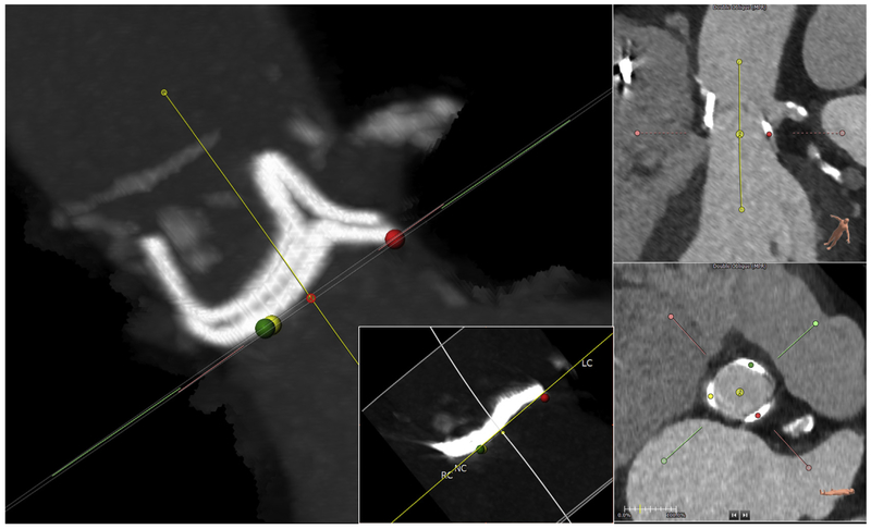
FIGURE 1. Define the Annular Plane.
Mark the exact annular plane. This is an orthogonal side view (maximum intensity projection) confirming that the selected annular plane is accurate for this Magna-Ease valve. The dots on the annular nadirs (green, right coronary cusp [RC]; yellow, noncoronary cusp [NC]) overlap, and the stent posts overlap in this so-called 2:1 orientation. Left coronary artery origin is seen at 2 o’clock. Multiplanar reconstruction shows the center of rotation (3-pronged star). (Inset) example of annular plane selected for a Mitroflow bioprosthetic, which typically assumes a sigmoidal configuration after implantation; the plane should abut at the lowest 3 points. LC = left coronary cusp.
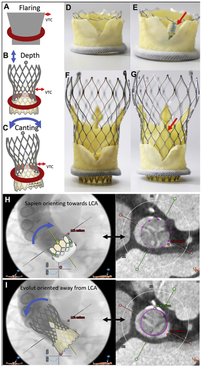
FIGURE 6. Confounding Transcatheter Aortic Valve Replacement Device and Implantation Characteristics.
Confounders from transcatheter aortic valve replacement (TAVR) device and implantation characteristics. (A to C) implantation characteristics including flaring, depth of implantation, and canting each significantly affect virtual valve-to-coronary (VTC) distance. (C to F) In vitro BASILICA TAVR inside a Mitroflow bioprosthetic valve using a SAPIEN 3 (D,E) and Evolut R (F,G). (D,F) TAVR device commissures are serendipitously aligned away from the laceration. (E,G) TAVR device commissures (red arrows) are aligned with the laceration and are more likely to obstruct coronary inflow. images courtesy of Danny Dvir. (H) Depiction of a SAPIEN aligning with a Mitroflow annulus and encroaching more on the left coronary artery (LCA). (I) In contrast, an Evolut R aligns with the ascending aorta and often orients away from the LCA.
In aortic roots with deficient sinuses, the virtual valve-to-coronary (VTC) distance is the main determinant of risk. The scenario of “sequestered sinus” requires a constellation of a low and narrow sinotubular junction, a tall and wide bioprosthetic valve frame and leaflets, and a large transcatheter heart valve, among others.
ANNULUS.
The annular plane should first be defined using 3-point techniques common to all TAVR planning (11).
For valve-in-valve, when bioprosthetic stent struts are visible, the annular plane should be adjusted from an orthogonal (side) projection using maximum or average intensity projection computer reconstruction tools. Symmetrical bioprosthetic frame planes should be defined when uniform frame posts overlap in “2-1” configurations (Figure 1). The geometric center of the annulus serves as the center of rotation for the modeled TAVR device, influencing VTC measurements.
With an accurate plane defined, conventional TAVR measurements such as coronary height and sinus of Valsalva width are recorded. Coronary height by convention is measured to the lowest part of the ostium. Coronary height measured to the highest part of the ostium may aid in the interpretation of leaflet length.
LEAFLET.
Leaflet lengths are measured from the annular plane and are viewed in short axis at the levels of the coronary ostia and sinotubular junction. If leaflets are shorter than the coronary height, there is little obstruction risk. Conversely, leaflets that extend higher than the sinotubular junction are potentially obstructive when the sinotubular junction is narrow compared with the intended transcatheter valve. Bulky calcific masses on distal leaflet surfaces probably preclude BASILICA, risk embolism, and risk coronary obstruction through a different (ball-valve) mechanism than BASILICA can address.
For valve-in-valve, bioprosthetic leaflets manufactured from pig valves are likely to retract or “shorten” after TAVR, compared with native and pericardial bioprosthetic leaflets.
VIRTUAL VALVE AND INTENDED TRANSCATHETER VALVE.
A “virtual” valve is implanted at the geometric center determined earlier. For the purpose of VTC distance measurements, the TAVR device is simplified as a cylinder with a diameter equal to the maximum likely outward displacement of the existing valve leaflets. The selected diameter takes into consideration transcatheter valve designs that taper inward (such as Evolut) or that flare (such as SAPIEN) when constrained by bioprosthetic stent frames.
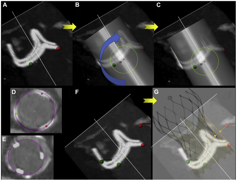
For valve-in-valve, the virtual valve is adjusted to align with the bioprosthetic frame posts, in volume reconstruction and multiplanar reconstruction modes at all levels. This time-consuming step defines VTC distance. The selected outer diameter of the virtual valve cylinder model is influenced by the bioprosthetic frame and the selected TAVR device design and strategy (Figure 2). Bioprosthetic stent frames constrain expansion of all valve types. The “waist” of self-expanding CoreValve Evolut R and PRO models is narrower than the nominal annular diameter and is still lower in situ compared with on the benchtop. We use the nominal waist of these valves as a most conservative estimate when planning BASILICA (20, 22, 23, and 24 mm wide for Evolut R and PRO models 23, 26, 29, and 34, respectively). These diameters may be further constrained by the bioprosthetic valve and also depend on depth of implantation. By contrast, balloon-expanded SAPIEN 3 valves tend to flare outward, exacerbating coronary obstruction risk, especially after bioprosthetic valve fracture (12).
FIGURE 2. Expected Outer Diameter.
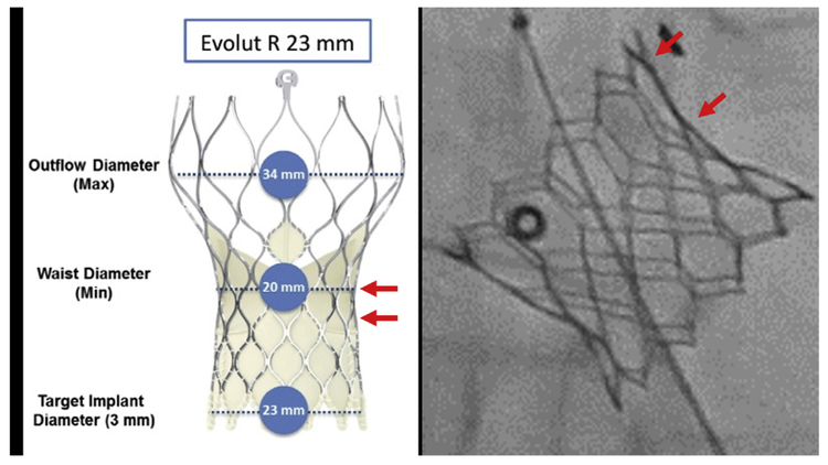
The expected outer diameter of the intended transcatheter aortic valve replacement device is selected, considering the diameter of the waist (left) and the impact of constraint by the surgical valve such as flaring (right, arrows) of a SAPIEN 3. Reproduced with permission from Medtronic.
Both the skirt and the commissural posts of the intended transcatheter heart valve can obstruct flow despite BASILICA (Figures 6E and 6G). In the setting of “deficient sinus of Valsalva,” the TAVR commissural posts risk obstruction, even despite BASILICA. In this setting, valve models with tall skirts and broad commissures (such as the Evolut PRO) pose higher risk.
VTC DISTANCE AND VIRTUAL VALVE-TO-SINOTUBULAR JUNCTION DISTANCE.
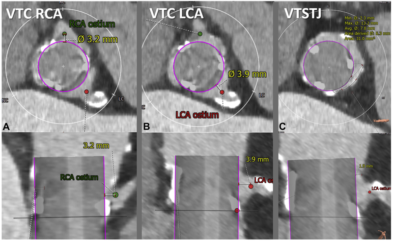
With the virtual valve properly positioned, it is straightforward to measure the VTC and virtual valve–to–sinotubular junction (VTSTJ) distances. We define the coronary artery ostium as the most proximal location that would be stented for atherosclerosis, to distinguish from the more proximal coronary ampulla that if included would exaggerate obstruction risk. A VTC distance <3 to 4 mm is considered high risk (4) on the basis of valve-in-valve outcomes; its value in native TAVR is less clear.
VTC distance probably overestimates the in situ distance between the valve and coronary ostium. Conventional VTC distance does not account for leaflet thickness. Conventional VTC distance is measured in systole, even though annular (13) and sinus (14) dimensions are smaller during diastolic coronary filling. A future successor to VTC distance may incorporate these corrections.
VTSTJ distance is even less well understood, except as an oversimplification of a crescent-shaped cross-sectional inflow (Figure 4). VTSTJ distance may be important only when circumferentially it is close to zero, because of the crescent-shaped blood inflow at the sinotubular junction. This is corroborated by the cohort with delayed coronary obstruction in a study by Jabbour et al. (5), most of whom had diameter differences between the valve and sinotubular junction of ≤3 mm, corresponding to an average VTSTJ distance ≤1.5 mm and not taking into account leaflet thickness.
FIGURE 4. Measure Virtual Valve-to-Coronary Distance and Virtual Valve-to-Sinotubular Junction Distance.
The virtual valve-to-coronary (VTC) distance is measured in 2 orthogonal planes (top, axial; bottom, longitudinal). Representative VTC distance measurement for a right coronary artery (RCA) (A) and left coronary artery (LCA) (B). The valve-to-sinotubular junction (VTSTJ) distance is measured in orthogonal planes (C): axial (upper) and longitudinal (lower), when the sinotubular junction is lower than the height of the transcatheter aortic valve replacement device.
LEAFLET TARGETS AND CALCIFICATION.
The BASILICA traversal target is at the leaflet nadir, which is the hinge point in native leaflets. BASILICA may fail if the leaflet is traversed closer to the tip. For most bioprosthetic valves, this nadir is elevated several millimeters above the annular plane.
The target must be calcium free for BASILICA traversal to succeed. Computed tomographic artifacts generated by bioprosthetic stent frames may obscure calcium-free targets. Higher performance computed tomographic scanners and metal-artifact reduction computed tomographic reconstruction algorithms may help (15). Once the guidewire traverses the leaflet, BASILICA laceration generally succeeds even if the rest of the leaflet is diffusely calcified.
PROJECTION ANGLES.
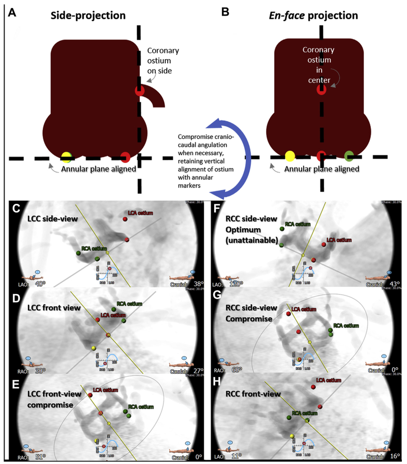
For each leaflet there are 2 cardinal fluoroscopic projection angles. A side projection (Figure 5A) depicts the coronary artery tangential to its origin, and a front or en face projection (Figure 5B) views the centerline of the leaflet. The optimal side projection of the right coronary cusp (RCC) is usually not attainable, so a third “compromise” projection is planned.
FIGURE 5. Projection Angles.
Computed tomographic prediction of fluoroscopic projections. First the annular plane is defined by the 3 annular nadir points (red, left coronary cusp [LCC]; green, right coronary cusp [RCC]; yellow, noncoronary cusp), along with corresponding coronary ostia. (A) The side projection is selected along the annular plane so that the intended annular marker and coronary ostium are on the lateral aspect of the aortic root, and the contralateral annular markers are overlapping. (B) In en face projection, the annular marker and corresponding coronary ostium lie along the centerline of the aortic root, and the annular markers are evenly spaced in a “1-1-1” projection. If either of these projections is fluoroscopically unattainable, the craniocaudal angulation is reduced, while preserving the side or center alignment, until an attainable projection angle is obtained. (Bottom) Representative LCC projections (C to E and Online Video 1) and RCC projections (F to H and Online Video 2). (C,F) Optimal side views. (D,H) Optimal en face views. (E,G) Compromise projections with reduced craniocaudal.
To identify the specific projection angles, rotate the aortic root depiction on the computed tomographic workstation along the simulated fluoroscopic projection angle “S curve” defined by the annular plane. The method relies on the point markers placed earlier to define the annulus using the center-nadir of each aortic leaflet cusp. The optimal side projection of the left coronary cusp (LCC) corresponds to the RCC and noncoronary cusp markers’ overlapping. The optimal front or en face projection of the LCC in this example is unattainable, so we find an attainable compromise left-right oblique angle by reducing craniocaudal angulation while still centering the left cusp marker midway between the RCC and noncoronary cusp markers (Online Video 1).
The optimal side projection of the RCC corresponds to the left and noncoronary cusp markers’ overlapping but is usually fluoroscopically unattainable. A compromise side projection is typically a lateral projection. The en face projection of the RCC is identified along the S curve with the right cusp marker midway between the LCC and noncoronary cusp markers (Online Video 2).
In settings in which the sinus of Valsalva is deficient, it may be more important for the en face projection to align precisely with the coronary artery origin rather than the leaflet midline. In this circumstance, the left and right coronary ostial markers are used instead of annular markers for projection planning.
CONFOUNDERS.
Unfortunately, the computed tomographic plan may not account for other contingencies that affect coronary inflow. Confounders include implantation characteristics, features of both the surgical and transcatheter valves, and anatomic variations. As a result, some BASILICA procedures appear less clearly indicated in retrospect.
Implantation characteristics (Figures 6A to 6C) affect VTC distance but may not easily be predicted on CT, including implantation depth, implantation canting angle, and TAVR device flaring. For example, higher implantation of Evolut valves may change the frame waist diameter and therefore VTC distance.
TAVR rotational alignment (Figures 6D to 6G) affects coronary obstruction as well. The pledgeted post of the SAPIEN 3 may obstruct the coronary ostium, even after BASILICA. Rotational alignment is not readily controlled by the operator. The pericardial-covered commissure of the Evolut valves covers a comparably larger proportion of the valve circumference and is longer than the SAPIEN. The radiopaque Evolut “half-hat” commissural marker, when oriented toward the greater aortic curvature, generally results in favorable native commissural alignment.
Longer TAVR devices may achieve different coaxiality (Figures 6H and 6I) than shorter TAVR designs. Especially in BASILICA candidates with narrow ascending aortas, longer Evolut valves align along the centerline between annulus and sinotubular junction. By comparison, shorter SAPIEN valve alignment is determined by the annulus and delivery system. We have less experience with other TAVR devices.
Expansion of the valve implant may be constrained uniformly or nonuniformly by the bioprosthetic frame and/or native valve calcification. The funnel-shaped coronary ostium may provide more ample separation from the leaflet than predicted.
Surgical bioprosthetic device characteristics affect VTC interpretation (Online Figure 4). Porcine leaflets tend to retract toward the annulus during TAVR implantation away from coronary ostia; native and bioprosthetic pericardial leaflets do not. Bulky surgical valve frames may protect coronary ostia, unless the bioprosthetic leaflets are mounted outside them to enhance effective orifice area (such as Mitroflow, Sorin Livanova, or Trifecta, St. Jude Abbott). Surgical stent struts may lie in front of coronary ostia, especially when implanted to treat bicuspid valve failure, where the 2 coronary arteries lie opposite each other. Surgical valve stent frames may constrain maximal expansion of the TAVR device, especially if bioprosthetic valve fracture is not planned. As mentioned, VTC distance does not take into account leaflet thickness or diastolic aortic root dimensions, so “true” VTC distance is probably lower than recorded.
Coronary arteries may be protected from occlusion by coronary artery bypass grafts, so knowing this surgical anatomy is important in BASILICA planning.
Eccentric coronary artery ostia, meaning not aligned with aortic valve leaflet centerlines, may affect obstruction risk and the effectiveness of BASILICA (Online Figure 5). In the setting of “deficient sinus” or near-zero VTC distance, the BASILICA laceration must be aligned with the coronary ostium. Otherwise, we recommend midline BASILICA leaflet laceration to create better inflow. Coronary ostial ampullae create ambiguity about the separation between displaced valve leaflets and coronary inflow.
It remains unclear whether VTC distance should be measured during diastole or systole.
LIMITATIONS OF CT.
Technical limitations of specific computed tomographic acquisitions can be important. Small-volume detector arrays (64 slices and smaller) can create stitch artifacts that affect VTC distance measurement. Low temporal resolution can blur coronary ostial location and calcium-free targets. Noncontrast CT obscures leaflet characteristics, including height and thickness. Failure to dilute intravenous contrast using saline “chaser” injection creates superior vena cava “beam-hardening” artifact that obscures aortic root features.
Contrast aortography during balloon aortography has been used to predict TAVR-induced coronary artery obstruction (16). Its role remains unclear, including the impact of undersized balloons, the positioning of the angiography catheter above or inside the aortic root, and its comparative value versus CT.
PRINCIPLES OF TRANSCATHETER ELECTROSURGERY
BASILICA is part of the family of transcatheter electrosurgery procedures we developed to deliver cavalaortic access sheaths (17) and to lacerate valve leaflets (6,7,18) but dates earlier to electrification of needles to traverse interatrial septa (19) and atretic pulmonary valves (20) and of catheters to ablate myocardial conduction pathways. BASILICA uses unipolar alternating-current radiofrequency ablation energy by establishing a current path between the BASILICA guidewire and a dispersive electrode on the patient’s skin, both connected to an electrosurgery generator.
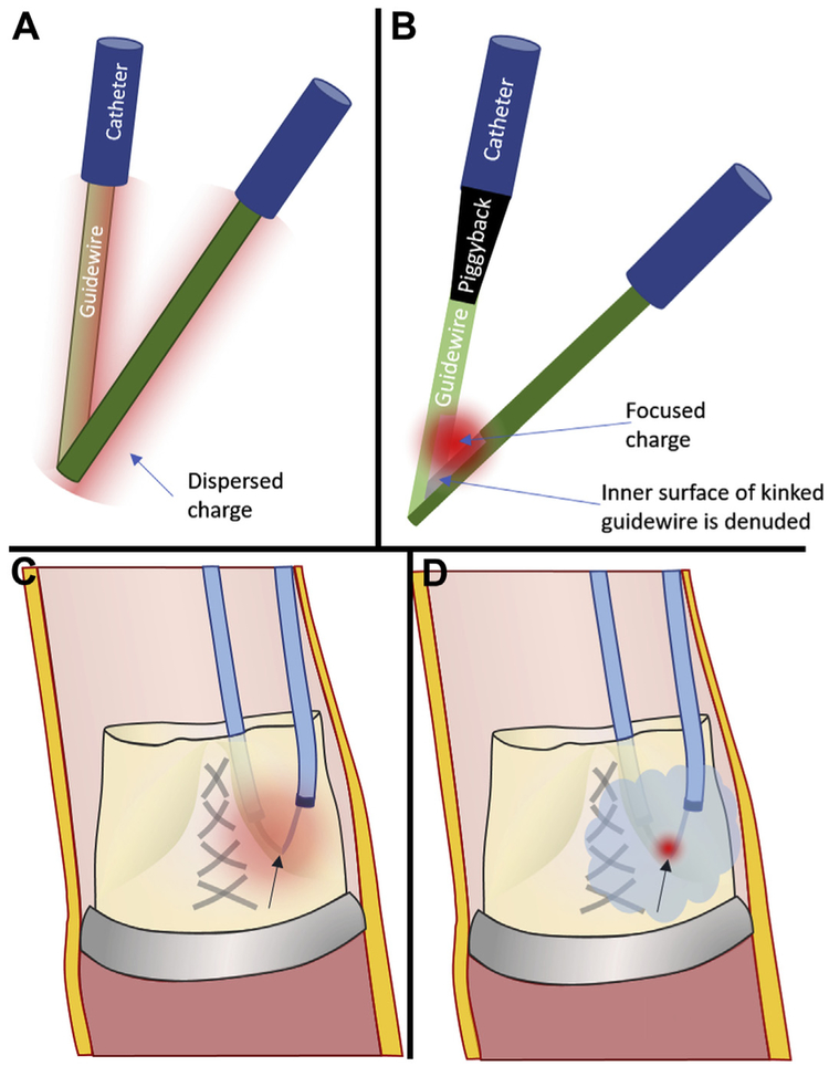
BASILICA relies on concentration of charge on small surfaces to vaporize tissue. Charge is focused onto leaflet targets using polymers to insulate the guidewires and by displacing blood using nonionic fluid. During the leaflet traversal step of BASILICA, charge is concentrated on the tip of a commercial off-the-shelf stiff coronary guidewire (Astato XS20, Asahi-Intecc, Tokyo, Japan) by positioning an insulating polymer microcatheter close to the tip (such as Piggyback Wire Converter, Teleflex, Wayne, Pennsylvania). During the leaflet laceration step of BASILICA, charge must be concentrated “unnaturally” along the inner curvature of a kinked guidewire straddling both sides of the leaflet to be lacerated. To accomplish this, the guidewire is focally denuded of insulating polymer coating along 1 to 2 mm of the kinked inner surface. We avoid charge dispersion (and loss of electrosurgery efficiency) by flooding the field with 5% dextrose in water, which does not conduct current (Figure 7). Dextrose flooding disrupts alternative current paths and focuses current along the point of contact between lacerating wire and leaflet tissue. Dextrose flooding simultaneously prevents char formation, thrombosis, and thromboembolism. Substituting dextrose with saline vastly diminishes laceration efficiency.
FIGURE 7. Principles of Transcatheter Electrosurgery.
(A) Charge (diffuse red cloud) will disperse around a kinked guidewire without (B) selective denudation of insultation from the inner-curve (“elbow”), which focuses charge (focal red cloud). (C) Even after focal denudation, blood ions will disperse charge. (D) Flooding the field with nonionic dextrose confines radiofrequency energy to the lacerating surface contacting the leaflet.
HOW BASILICA PREVENTS CORONARY OBSTRUCTION
BASILICA aims to prevent coronary obstruction caused by leaflet displacement from TAVR. This is easy to achieve when the sinus of Valsalva is preserved (“sinus sequestration”) because any reasonable blood inflow across a split leaflet can meander through the sinus of Valsalva into the coronary arteries. In other words, a BASILICA laceration almost anywhere along the leaflet will protect coronary flow as long as there is unencumbered space in the sinus of Valsalva. Conversely, it is difficult to preserve coronary flow when the sinus of Valsalva is effaced (“deficient sinus”); in this case, BASILICA leaflet laceration must be exactly aligned with the coronary artery ostium, and the TAVR must splay the split aortic leaflets to lay astride the coronary ostium, or there will be coronary obstruction.
Alignment and position of the TAVR device skirt and commissure also become more important when the sinus of Valsalva is deficient. Coronary obstruction is also more likely despite successful BASILICA when the TAVR device skirt lands higher than the coronary ostium or when, despite attempts to control the rotational orientation of the device, the leaflet commissural posts overlie the coronary ostium.
Leaflet cusps should be lacerated from base to tip and along their midline. Splits too close to the tip or too far from midline Central Illustration) may fail to allow coronary flow. Moreover, the split leaflets must “splay” outward (Central Illustration, Figures 6D and 6F) beyond their orthotopic position after TAVR. If the leaflets are trapped despite laceration, as for example in TAVR-in-TAVR, blood may not pass into the coronary artery.
Conveniently, lacerated leaflets coapt, albeit imperfectly, during the interval between BASILICA and TAVR. As a result, the iatrogenic aortic regurgitation usually is tolerated.
BASILICA TRAVERSAL AND LACERATION TECHNIQUE
Understanding aortic root anatomy provides insight into the required catheter shapes for BASILICA. The aortic root and the aortic arch lie in 2 different planes. The aortic root projects anterior and leftward. This can be modeled by a “spooked” cat arching its back and turning its head leftward, where the cat’s head is the position of the aortic root, and the cat’s right ear is the origin of the right coronary artery (Online Figure 6). BASILICA catheters aim at the base of the leaflets, away from the coronary arteries. Oversized left coronary catheters approach the left leaflet; straightened right coronary catheters engage the right leaflet base. Newly available catheter shapes ease BASILICA leaflet traversal (21).
EQUIPMENT FOR BASILICA.
Because there are not yet purpose-built devices, BASILICA requires available devices to be used off-label. Table 4 lists the required equipment. Some specific items must not be substituted, especially the 0.014- to 0.035-inch Piggyback Wire Converter, a locking, hubless microcatheter that serves first to insulate the guidewire shaft to concentrate charge to the traversing or lacerating surfaces and second to provide a radiographic marker. A conventional “hubbed” microcatheter can accomplish the same goal but with difficulty for experienced and inexperienced operators alike.
TABLE 4.
Equipment Required to Perform BASILICA
| Stage and Device | Comment |
|---|---|
| Access | |
| Suture femoral closure device (such as Perclose ProGlide, Abbott) |
|
| Sheath: DrySeal Flex 14-22 F × 33 cm (W.L. Gore) |
|
| Sheath: eSheath (Edwards Lifesciences) |
|
| Sheath: large Check-Flo Performa 18-20 F (Cook) |
|
| Targeting and traversal | |
| Single-loop snare: 20-30 mm (Amplatz Goose Neck, Medtronic) |
|
| Guidewire: 0.018-inch stiff (such as V-18, Boston Scientific) or 0.014-inch stiff (such as Spartacore, Abbott) anchor guidewire |
|
| Snare guiding catheter: multipurpose or R Judkins, 6 F × 100 cm (vendor agnostic) |
|
| For left leaflet (in order of preference): AL2, AL3, AL4, EBU3.75, EBU4, EBU5 guiding catheters, 7- to 8-F × 100 cm (vendor agnostic) |
|
| New “pachyderm” curves: PAL1, PAL2, PAL3 (Launcher, Medtronic) | |
| For right leaflet (in order of preference): JR4, MP, IM, AR1 guiding catheters, 7- to 8-F × 100 cm (vendor agnostic) |
|
| New “pachyderm” curve: PJR4 (launcher, Medtronic) | |
| Internal mammary (IM) curve diagnostic catheter, 5-F × 125 cm length (e.g., EXPO or Impulse, Boston Scientific) |
|
| Insulating polymer jacket (hubless locking 0.014-inch microcatheter) (Piggyback wire converter, 145 cm, Teleflex) |
|
| Stiff 0.014 inch × 300 cm guidewire (Astato XS 20, Asahi-Intecc) |
|
| Laceration | |
| Electrosurgery pencil and dispersive electrodes |
|
| Needle driver |
|
| Scalpel blade such as #11 |
|
| Electrosurgery generator (e.g., Valleylab Force/FX, Medtronic) | |
| Torquers 0.014 inch |
|
| Torquers 0.035 inch |
|
| 60-ml luer lock syringes each with 12- to 24-inch extension tubing. |
|
| 6-F angled pigtail |
|
LVOT = left ventricular outflow tract; other abbreviations as in Table 1.
OVERVIEW AND PROCEDURE SEQUENCE.
The procedure can be performed using moderate sedation, but many teams elect general anesthesia to facilitate transesophageal echocardiography. The key laceration step of the procedure currently requires extra hands, but fast-track recovery and discharge remain the default.
After vascular access, accessory catheters are placed, such as temporary pacemaker and cerebral protection devices, if used. Next, the BASILICA snare and traversal catheters are positioned. In doppio BASILICA, the RCC should probably be targeted first because the projection angles are less optimal. BASILICA catheters for the first targeted leaflet are usually introduced through the TAVR access. After electrosurgical traversal of each leaflet, the guidewire is snared. Next, the Piggyback catheter is withdrawn to mark the point on the midshaft of the guidewire that is focally denuded and kinked to create a lacerating surface. Next, the target leaflets are lacerated in sequence, with a pigtail catheter positioned in the left ventricle at the first opportunity. Next, the pigtail is exchanged for the TAVR guidewire (and sheath if not already in place). Finally, TAVR is performed as usual, with bioprosthetic valve fracture as desired, followed by vascular hemostasis.
Single-leaflet (“solo”) BASILICA procedures are less demanding than 2-leaflet (“doppio”) procedures because fewer percutaneous arterial catheters are required, because they take less time, and because the TAVR guidewire or pigtail catheter can more easily be pre-positioned in the left ventricular apex before any laceration procedures. Similarly, LCC BASILICA is less demanding than RCC BASILICA because a side projection is usually attainable in the former but not the latter.
VASCULAR ACCESS.
Each leaflet laceration requires 2 arterial catheters. We recommend 1 or 2 large transfemoral sheaths, for solo or doppio procedures, respectively. One specific introducer sheath (DrySeal Flex, Gore Medical, Flagstaff, Arizona) is hemostatic when using multiple simultaneous catheters in parallel. Transcaval access (22,23) can be helpful.
Solo BASILICA can be performed with no extra arterial access. One BASILICA catheter is positioned through the TAVR-access DrySeal Flex sheath and the second through the contralateral sheath for the pigtail catheter. In doppio BASILICA, 2 catheters are introduced through the TAVR access-side sheath and 2 others through the contralateral large-bore sheath. After the first BASILICA laceration, the DrySeal Flex sheath is replaced if necessary for TAVR.
LEFT VENTRICULAR OUTFLOW TRACT CATHETER AND SNARE.
First, pre-position a snare in the left ventricular outflow tract (LVOT). This may require crossing a stenotic aortic valve and exchanging for the snare catheter (Online Figure 7). The snare is sized to match the average diameter of the LVOT. The snare is inserted using a rotating hemostatic valve through a multipurpose or right Judkins-shaped 6-F coronary guiding catheter, positioned just below the annulus. Positioning too low risks entrapment and damage to the mitral subvalvular structures. Guiding catheter position is stabilized using a rigid guidewire anchor (such as a 0.014-inch Spartacore [Abbott, Santa Clara, California] or a V-18 [Boston Scientific]) in the left ventricular apex alongside the snare.
LCC TRAVERSAL CATHETER.
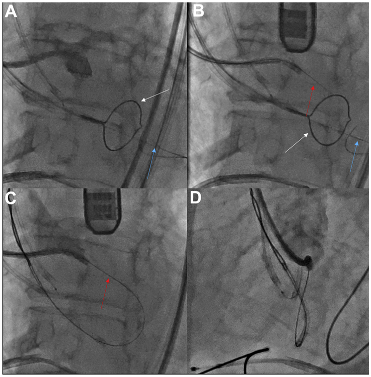
A guide catheter is selected that is “too long” to engage the left coronary artery and therefore aims at the leaflet base. In a side projection, the catheter should contact the leaflet base and point toward the LVOT, or else a nontarget structure (the left atrium) will be entered. If the selected LCC catheter does not point to the LVOT, a longer tip catheter can be substituted (such as an AL4 instead of an AL3). A representative LCC traversal and ensnarement is shown in Figure 8. A representative solo left BASILICA is demonstrated in Online Video 3.
FIGURE 8. Left Coronary Cusp Traversal and Snare.
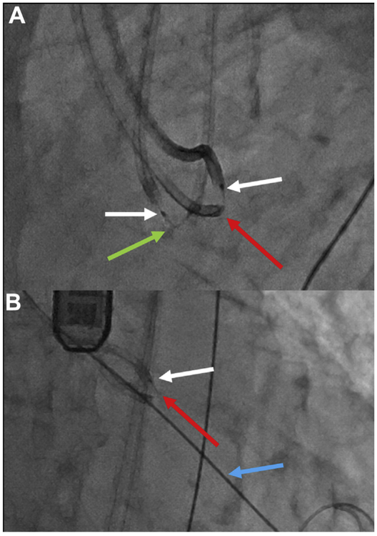
Traversing the Left coronary cusp (LCC). (A) Side projection showing the LCC hinge point. (B) A sigmoid-shape coaxial crossing system combines a Long 5-F IM catheter inside a 7-F EBU guide catheter. The electrified Astato wire (red arrow) is traversing the leaflet, aimed at the left ventricular outflow tract (LVOT) snare (white arrow) stabilized by an anchor wire (blue arrow) in the left ventricular apex. (C,D) Angiography in side and en face projections, respectively, demonstrates that the traversal point is at the hinge point and midline (Online Video 3).
Otherwise, we recommend that a coaxial catheter pair be selected as in our original BASILICA series. This creates a sigmoid shape (Online Figures 8A and 8B). The larger outer guiding catheter reaches the LCC and points outward, while the inner mammary curve catheter is pointed downward, away from the coronary ostium toward the LVOT. Maintaining the catheters in “trans” configuration (pointed in opposite directions) can be difficult and benefits from an interposed Tuohy-Borst rotating hemostatic adapter to lock the relationship between the two (Online Figure 8C). Extending or retracting the inner catheter can deflect or straighten the catheter shape, respectively. A good example is a long (125 cm × 5 F) diagnostic internal mammary curve catheter inside a 6- to 8-F AL or EBU guiding catheter. Newly available catheter shapes (PAL1, PAL2, or PAL3 or PJR4, Medtronic) (Online Figures 8D and 8E) are easier to use than coaxial catheter pairs (21).
We use 2 approaches to enhance the torque responsiveness of the traversal system. One approach is to use large (7- or 8-F) guiding catheters. Another is to insert the back end of a standard or rigid 0.035-inch guidewire into the guiding catheter alongside the traversal system. Another benefit of the rigid wire is that interactively, it can straighten the guiding catheter secondary curve, which has the effect of pointing the traversal catheter inward toward the LVOT centerline. Both approaches are equally applicable to left and right coronary traversal.
RCC TRAVERSAL CATHETER.
Traversing the RCC is more difficult than traversing the LCC, because an optimal angiographic side projection is usually not attainable but also because optimal catheter shapes have not been commercially available. We recommend using a R Judkins guiding catheter with its secondary bend straightened using the back end of a rigid 0.035-inch guidewire, or alternatively using a multipurpose curve. The newly available PAR1 curve (Medtronic) (Online Figure 8E) is designed around the typical anatomy of the aortic root described earlier (Online Figure 6) and may be easier to use (21).
COAXIAL CROSSING DEVICES.
With the traversal catheter in place, the coaxial crossing system is positioned. A stiff conductive guidewire (Astato XS-20, 0.014 inches × 300 cm, Asahi-Intecc) is positioned with its tip just beyond an insulating jacket (Piggyback Wire Converter). The insulating 1 cm of coating should be scraped off the back end of the guidewire using a scalpel blade outside of the body, to allow it to conduct electricity when clamped to the electrosurgery pencil using forceps (Online Figure 9). Electrosurgery pencils must not have polymer surface coating (such as Edge, Medtronic); any insulating coating must be scraped off with the scalpel.
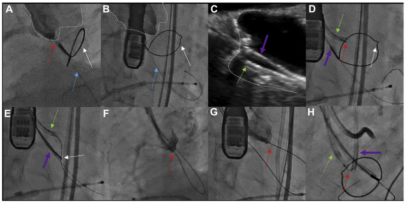
The crossing catheter is positioned and aimed in the fluoroscopic side projection, and the aim is confirmed midline in the fluoroscopic en face projection (Figures 8A and 8B). The snare outlines the LVOT target (Figures 9A and 9B). Unfortunately, a side projection is usually not attainable for the RCC. If fluoroscopy is insufficient, appropriate aim toward the RCC hinge point can usually be confirmed by optional transesophageal echocardiography (Figures 9C and 9D).
FIGURE 9. Right Coronary Cusp Traversal and Snare.
Traversing the right coronary cusp (RCC) in native aortic valve disease. (A,B) Side and en face projections, respectively, with angiography through a RCC Judkins right guide directed at the traversal point. The aortic root is outlined. Red arrow indicates Astato wire; blue arrow indicates anchor wire to stabilize the snare; white arrow indicates left ventricular outflow tract (LVOT) snare. (C) Transesophageal echocardiography confirming orientation of the RCC guide (green arrow), which must be distinguished from the LVOT guide catheter (purple arrow). (D) Electrosurgical traversal. The Astato wire (red arrow) is crossing the target leaflet. (E) The Astato wire is snared via the LVOT catheter. (F,G) Angiography shows the Astato across the traversal point in the side and en face projections, respectively (H). The “flying V” configuration with the kinked and denuded Astato shaft (red arrow) straddling the leaflet. The piggyback tip is in position via the RCC guide. A left coronary cusp (LCC) guide and LVOT snare are in place for LCC traversal.
TRAVERSAL AND SNARING.
With the snare positioned in the LVOT, the traversal catheter is positioned at the hinge point target, the coaxial crossing system abutting the target tissue with only the guidewire tip exposed, and the back of the wire connected to the electrosurgery generator.
Electrosurgical radiofrequency energy is applied in pure cut mode typically at 50 W while gently advancing the guidewire at a rate of approximately 2 to 5 mm/s, for a distance of only about 2 to 5 mm. Cut mode vaporizes tissue. Apply energy only for <1 s. Prolonged electrification induces char formation that reduces additional traversal efficacy.
If the guidewire fails to advance, ensure that the electric connections are intact and not “short circuited” by, for example, wet towels or wire loops. More often, the guidewire fails to advance because of calcification at the leaflet contact point. In this case, the crossing system needs subtle repositioning and additional traversal attempts.
Once the wire advances just below the annular plane, electrosurgical energy application should stop, and the wire should be further advanced without electrification approximately 20 mm (Figure 8B). Ideally, the wire advances into the snare. Otherwise, the snare catheter is manipulated until the wire is grasped.
The snare grasp should be 10 to 15 mm from the tip. With a confirmed grasp, the anchor wire is withdrawn and removed. Next, the ensnared wire is invaginated into the LVOT catheter. Take care not to withdraw the snare more than a few centimeters, to allow creation of the “flying V” laceration surface.
Confirm that the leaflet is grasped, and confirm the leaflet traversal position by angiography, at least in a side projection, via the traversal guiding catheter (Figures 8C, 8D, 9F, and 9G).
SNARING AND THE “FLYING V.”
The LVOT catheter and ensnared wire are kept in the aortic root to prepare the “flying V” laceration surface.
First, the Piggyback polymer jacket is withdrawn outside the body until only 5 to 7 cm of the most proximal Astato guidewire remains exposed. Lock the Piggyback, load one 0.035-inch Torque device over it, and lock one 0.014-inch Torque device against the Piggyback to secure it in place.
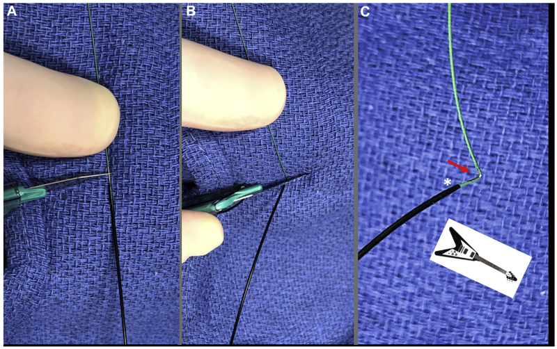
Place a towel behind the Piggyback tip along the Astato guidewire midshaft (Figure 10). Focally denude a 1-mm length of guidewire approximately 120° around its circumference by scraping with a #11 scalpel blade. Then, carefully, without rotating the wire, elevate the wire from behind the towel and apply the blunt back of the scalpel blade to kink the wire at center of the denuded surface. Finally, pinch the guidewire from behind the towel to impart at least a 90° sharp kink to the guidewire. This maneuver creates the “flying V” lacerating surface, characterized by inner-surface denudation and outer-surface insulation alongside the Piggyback radiographic marker.
FIGURE 10. Flying V.
Preparation of the “flying V” inner-surface denuded guidewire. (A) Two to three millimeters of guidewire is scraped noncircumferentially immediately distal to the locked Piggyback. (B) Using the back end of the scalpel, the guidewire is kinked against fingers behind a raised towel. (C) Noncircumferential inner-surface denudation (arrow) near the Piggyback in a “flying V” configuration.
Next, load the “flying V” by widely opening and detaching the entire Tuohy-Borst rotating hemostatic valve from the traversal guide and pulling from the LVOT side. Once the kink enters the traversal guiding catheter, the Tuohy-Borst valve can be reattached. Take care not to forget at this point to insert the snare loader tube into the Tuohy-Borst valve to narrow the Tuohy-Borst lumen; otherwise the ensnared guidewire may slip out from the snare (Online Figure 10). It may be necessary to cut the snare-kinked guidewire kink to grasp and load it into a torque device. Continue pulling the guidewire until the “flying V” lacerating surface straddles the leaflet for laceration. Finally, release the catheter tension from the aortic valve leaflet to reverse any iatrogenic aortic regurgitation.
In doppio BASILICA procedures, repeat the aforementioned steps to position the second laceration catheter pair.
LACERATION INCLUDING DEXTROSE FLUSH.
Pre-position a pigtail catheter in the left ventricular apex, to be used later for TAVR, before laceration in a solo BASILICA procedure and before the second laceration in a doppio BASILICA. Pre-positioned TAVR guidewires are less desirable because they can couple electrically with the lacerating guidewire.
The technique of laceration is nearly identical to LAMPOON (7). Two large (60-ml) syringes are connected via extension tubing to the sidearms of the 2 BASILICA catheters, filled with 5% dextrose in water (Online Figure 11). Take care to remove gas and not to allow blood reflux. Isotonic dextrose in water is nonionic. When dextrose flush displaces blood, the only available electric current path for an electrified “flying V” is through the tissue it is contacting. Absent dextrose flush, electric current disperses through the blood pool, significantly reducing laceration energy. Moreover, blood in contact with the high-energy electrification forms char that reduces laceration efficiency and forms blood clots that can embolize.
Three staff members are helpful to perform the laceration: one to pull on the laceration catheters, one to inject dextrose, and one to activate the electrosurgery pencil. Secure the vascular introducer sheaths using sutures. Confirm that: 1) the “flying V” is apposed to the leaflet target; 2) the Piggyback tip is close to the flying V (the radiographic marker is 2 mm from the tip); and 3) the 2 guiding catheters are within 5 mm of the tip (Figure 11). Initiate dextrose infusion at about 2 to 5 ml/s through each syringe simultaneously to clear catheters of blood. Then under fluoroscopic guidance, electrify the guidewire at 70 W while applying traction force up to 400g (roughly the weight of a pint of milk, 1 lb). Electrification times of 5 to 20 s are common, with shorter times for porcine and native valve leaflets and longer times for pericardial leaflets. Heavier traction force should not be required and risks mechanical leaflet avulsion rather than laceration.
FIGURE 11. Laceration.
Laceration of 2 leaflets in sequence. (A) The kinked and denuded Astato (green arrow) across the right coronary cusp (RCC) is in a “flying V” configuration, with the adjoining Piggyback (white arrow). The Left coronary cusp (LCC) laceration system also is evident with a separate “flying V” (red arrow) and Piggyback (white arrow). (B) After RCC laceration, the transcatheter aortic vaLve repLacement guidewire (blue arrow) is positioned in the Left ventricLe, and then the LCC guidewire is electrified for laceration.
Take care not to withdraw the conjoined BASILICA catheters past the aortic arch to minimize the risk for vascular injury. Withdraw the Astato guidewire from the traversal guiding catheter; this requires considerable force to overcome the kink. One BASILICA catheter is often used for TAVR angiography. Optional transesophageal echocardiography confirms an adequate laceration.
Finally, TAVR is performed as usual.
UNRESOLVED QUESTIONS AND FUTURE DIRECTIONS
We often lack certainty as to whether individual patients, identified as at high risk for coronary obstruction, could undergo TAVR successfully without BASILICA or other coronary protection strategies. In other words, we consider our approach to identifying obstruction risk to be sensitive but nonspecific. Improved prediction tools are desirable, but solutions are not obvious to us.
The risk for stroke associated with BASILICA in our early experience may be higher than in recent pivotal TAVR and cerebral embolic protection trials (24-26). BASILICA entails catheter-leaflet interaction and mechanical leaflet disruption beyond ordinary TAVR. The benefit of routine catheter cerebral protection during BASILICA TAVR is not known, but we suggest that at least it be considered before every case. We believe that BASILICA is sufficiently encouraging on the basis of early experience that we lack clinical equipoise to perform a randomized comparison of BASILICA with alternative approaches. We believe that patients should participate in the decision to undergo BASILICA on the basis of the risks and alternatives, such as surgical aortic valve implantation, the possibly of significantly increased stroke risk, and the availability of local expertise. Table 5 summarizes advantages and disadvantages of BASILICA.
TABLE 5.
Advantages and Disadvantages of BASILICA
| Advantages of BASILICA | Disadvantages of BASILICA |
|---|---|
| Conceptually simple | Has many unfamiliar steps; can be difficult in practice Not suitable for coronary obstruction caused by TAVR fabric skirt or by TAVR commissure Not suitable for most TAVR-in-TAVR |
| Does not leave behind a deformable or prothrombotic stent implant, such as “snorkel” stent | Laceration may not be completely aligned with coronary ostium, as in “sinus deficiency” mechanism of coronary obstruction |
| Relatively straightforward for “sinus sequestration” mechanism of coronary obstruction | More demanding for “sinus deficiency” mechanism of coronary obstruction |
| Relatively straightforward for LCC | Relatively challenging for RCC because of difficult projection angles |
| If a leaflet can be traversed, it almost always can be lacerated | Not suitable for bulky calcific leaflet nodules, which can cause coronary obstruction by mass effect |
| Confidence in need for BASILICA is high when VTC distance is low (<3 mm) | Poor specificity in predicting risk (need for BASILICA) when VTC distance is low but ≥3 mm |
| Applicable to native as well as bioprosthetic aortic valve failure | Technically demanding in stentless aortic bioprostheses |
| Can be achieved using off-the-shelf catheter tools | Would benefit from purpose-built commercial catheter tools |
| Speculation that it improves flow patterns and reduces stasis both in sinuses and neosinuses of Valsalva | Strokes observed in prospective BASILICA IDE protocol |
| Attractive for patients who are at high risk for surgical aortic valve replacement | Less desirable choice for patients who are low or intermediate risk for surgical aortic valve replacement |
| Can be planned on CT | Should not be planned on angiography or echocardiography alone |
| Can be performed using moderate sedation and fast-track discharge | Requires extra “hands” for the actual laceration and may benefit from adjunctive transesophageal echocardiographic guidance |
| Avoids indefinite dual-antiplatelet therapy required after “snorkel” stenting | |
| Improved future coronary access |
Linear BASILICA lacerations may not adequately protect against coronary obstruction in certain TAVR-in-TAVR procedures because split leaflets may remain constrained by the prior TAVR frame. This appears especially applicable to contemporary TAVR devices with more bulbous leaflets.
We speculate that BASILICA changes blood flow patterns in the sinuses of Valsalva sequestered by the TAVR implant and in this way may reduce sinus thrombosis (27,28). It is interesting that hypo-attenuated leaflet thickening and hypoattenuation affecting motion were both observed (11% and 3%, respectively, in the first 30 days), in the prospective BASILICA trial (8) but never alongside lacerated leaflets.
We have little experience with BASILICA in conjunction with TAVR devices other than the SAPIEN 3 and CoreValve Evolut R.
The BASILICA technique has been applied to a small number of patients with bicuspid aortic valve failure (“Bi-SILICA”) (29). It may have value in enhancing circularity, facilitating expansion, and reducing paravalvular leak, but this remains to be established.
Dedicated BASILICA guiding catheters and combined traversal and laceration devices are under development. We predict that these catheters will substantially reduce the time and effort required to perform BASILICA. We speculate that dedicated devices might alter the risk-benefit profile of the procedure such that it might be performed more liberally.
CONCLUSIONS
Patients are frequently excluded from TAVR out of concern for coronary obstruction risk. CT appears to identify patients at risk for coronary obstruction but with poor specificity. Traditional transcatheter approaches to prevent or treat coronary obstruction, including prophylactic and bailout stent therapy, appear unattractive because of serious early and late ischemic complications.
BASILICA appears to be effective at preventing TAVR-induced coronary obstruction. It can be accomplished using off-the-shelf devices and after careful CT-based planning. It remains a complex procedure that some argue should be confined to specialty centers. We speculate that purpose-built devices might reduce the required operator expertise and might alter the risk-benefit balance so that it might be applied more liberally as a prophylactic procedure.
BASILICA has numerous steps, but it can be taught. This tutorial should provide a solid foundation for new operators, before they observe cases and undertake the procedure independently.
Supplementary Material
FIGURE 3. Virtual Valve Orientation.
Virtual valve orientation. With the annular plane identified (A), a virtual valve cylinder is implanted and rotated (B,C) to align with the surgical valve posts and annular plane. Simultaneous short-axis reconstructions confirm alignment with the center of the annulus (D) and valve posts (E). It is important to factor the geometry and expected constraint on the surgical valve (F,G) in measurements of virtual valve-to-coronary distance.
HIGHLIGHTS.
CT is sensitive but nonspecific to identify risk for TAVR-induced coronary obstruction.
BASILICA may prevent coronary obstruction in cases of native and valve-in-valve TAVR.
BASILICA is applicable to sinus sequestration and deficient-sinus mechanisms.
BASILICA is complex with available equipment, but dedicated equipment may simplify it.
Acknowledgments
This work was supported by grant Z01-HL006040 from the National Heart, Lung, and Blood Institute Division of Intramural Research (to Dr. Lederman). Drs. Lederman, Rogers, and Khan are co-inventors on patents assigned to the National Institutes of Health for purpose-built devices intended to lacerate valve leaflets. Dr. Rogers is a proctor for Edwards Lifesciences and Medtronic. Dr. Greenbaum is a proctor for Edwards Lifesciences, Medtronic, and Abbott Vascular; holds equity in Transmural Systems; and receives research support to his employer from Edwards Lifesciences, Abbott Vascular, Medtronic, and Boston Scientific. Dr. Babaliaros is a consultant for Edwards Lifesciences and Abbott Vascular; and receives research support to his employer from Edwards Lifesciences, Abbott Vascular, Medtronic, and Boston Scientific. Dr. Dvir is a consultant for Edwards Lifesciences, Medtronic, and Abbott Vascular. All other authors have reported that they have no relationships relevant to the contents of this paper to disclose.
ABBREVIATIONS AND ACRONYMS
- BASILICA
bioprosthetic or native aortic scallop intentional laceration to prevent iatrogenic coronary artery obstruction during TAVR
- CT
computed tomography
- LAMPOON
intentional laceration of the anterior mitral leaflet to prevent left ventricular outflow obstruction
- LCC
left coronary cusp
- LVOT
left ventricular outflow tract
- RCC
right coronary cusp
- TAVR
transcatheter aortic valve replacement
- VTC
virtual valve-to-coronary
- VTSTJ
virtual valve-to-sinotubular junction
REFERENCES
- 1.Ribeiro HB, Nombela-Franco L, Urena M, et al. Coronary obstruction following transcatheter aortic valve implantation: a systematic review. J Am Coll Cardiol Intv 2013;6:452–61. [DOI] [PubMed] [Google Scholar]
- 2.Ribeiro HB, Webb JG, Makkar RR, et al. Predictive factors, management, and clinical outcomes of coronary obstruction following transcatheter aortic valve implantation: insights from a large multicenter registry. J Am Coll Cardiol 2013;62:1552–62. [DOI] [PubMed] [Google Scholar]
- 3.Dvir D, Leipsic J, Blanke P, et al. Coronary obstruction in transcatheter aortic valve-in-valve implantation: preprocedural evaluation, device selection, protection, and treatment. Circ Cardiovasc Interv 2015;8:e002079. [DOI] [PubMed] [Google Scholar]
- 4.Ribeiro HB, Rodes-Cabau J, Blanke P, et al. Incidence, predictors, and clinical outcomes of coronary obstruction following transcatheter aortic valve replacement for degenerative bioprosthetic surgical valves: insights from the VIVID registry. Eur Heart J 2018;39:687–95. [DOI] [PubMed] [Google Scholar]
- 5.Jabbour RJ, Tanaka A, Finkelstein A, et al. Delayed coronary obstruction after transcatheter aortic valve replacement. J Am Coll Cardiol 2018;71:1513–24. [DOI] [PubMed] [Google Scholar]
- 6.Khan JM, Dvir D, Greenbaum AB, et al. Transcatheter laceration of aortic leaflets to prevent coronary obstruction during transcatheter aortic valve replacement: concept to first-in-human. J Am Coll Cardiol Intv 2018;11:677–89. [DOI] [PMC free article] [PubMed] [Google Scholar]
- 7.Babaliaros VC, Greenbaum AB, Khan JM, et al. Intentional percutaneous laceration of the anterior mitral leaflet to prevent outflow obstruction during transcatheter mitral valve replacement: first-in-human experience. J Am Coll Cardiol Intv 2017;10:798–809. [DOI] [PMC free article] [PubMed] [Google Scholar]
- 8.Khan JM, Greenbaum AB, Babaliaros VC, et al. The BASILICA trial: prospective multicenter investigation of intentional leaflet laceration to prevent TAVR coronary obstruction. J Am Coll Cardiol Intv 2019;12:1240–52. [DOI] [PMC free article] [PubMed] [Google Scholar]
- 9.Abramowitz Y, Chakravarty T, Jilaihawi H, et al. Clinical impact of coronary protection during transcatheter aortic valve implantation: first reported series of patients. EuroIntervention 2015;11:572–81. [DOI] [PubMed] [Google Scholar]
- 10.Blanke P, Soon J, Dvir D, et al. Computed tomography assessment for transcatheter aortic valve in valve implantation: the Vancouver approach to predict anatomical risk for coronary obstruction and other considerations. J Cardiovasc Comput Tomogr 2016;10:491–9. [DOI] [PubMed] [Google Scholar]
- 11.KaseL AM, Cassese S, BLeiziffer S, et al. Standardized imaging for aortic annular sizing: implications for transcatheter valve selection. J Am Coll Cardiol Img 2013;6:249–62. [DOI] [PubMed] [Google Scholar]
- 12.Chhatriwalla AK, Allen KB, Saxon JT, et al. Bioprosthetic valve fracture improves the hemodynamic results of valve-in-valve transcatheter aortic valve replacement. Circ Cardiovasc Interv 2017;10:e005216. [DOI] [PubMed] [Google Scholar]
- 13.Murphy DT, BLanke P, Alaamri S, et al. Dynamism of the aortic annulus: effect of diastolic versus systolic CT annular measurements on device selection in transcatheter aortic valve replacement (TAVR). J Cardiovasc Comput Tomogr 2016;10:37–43. [DOI] [PubMed] [Google Scholar]
- 14.Jurencak T, Turek J, Kietselaer BL, et al. MDCT evaluation of aortic root and aortic valve prior to TAVI. What is the optimal imaging time point in the cardiac cycle? Eur Radiol 2015;25:1975–83. [DOI] [PMC free article] [PubMed] [Google Scholar]
- 15.Kalisz K, Buethe J, Saboo SS, Abbara S, Halliburton S, Rajiah P. Artifacts at cardiac CT: physics and solutions. Radiographics 2016;36:2064–83. [DOI] [PubMed] [Google Scholar]
- 16.Patsalis PC, Al-Rashid F, Neumann T, et al. Preparatory balloon aortic valvuloplasty during transcatheter aortic valve implantation for improved valve sizing. J Am Coll Cardiol Intv 2013;6:965–71. [DOI] [PubMed] [Google Scholar]
- 17.Halabi M, Ratnayaka K, Faranesh AZ, Chen MY, Schenke WH, Lederman RJ. Aortic access from the vena cava for large caliber transcatheter cardiovascular interventions: pre-clinical validation. J Am Coll Cardiol 2013;61:1745–6. [DOI] [PMC free article] [PubMed] [Google Scholar]
- 18.Khan JM, Lederman RJ, Sanon S, et al. transcatheter mitral valve replacement after transcatheter electrosurgical Laceration of Alfieri stitch (ELASTIC): first-in-human report. J Am Coll Cardiol Intv 2018;11:808–11. [DOI] [PMC free article] [PubMed] [Google Scholar]
- 19.Justino H, Benson LN, Nykanen DG. Transcatheter creation of an atrial septal defect using radiofrequency perforation. Catheter Cardiovasc Interv 2001;54:83–7. [DOI] [PubMed] [Google Scholar]
- 20.Hausdorf G, Schulze-Neick I, Lange PE. Radiofrequency-assisted “reconstruction” of the right ventricular outflow tract in muscular pulmonary atresia with ventricular septal defect. Br Heart J 1993;69:343–6. [DOI] [PMC free article] [PubMed] [Google Scholar]
- 21.Lisko JC, Babaliaros VC, Lederman RJ, Khan JM, Rogers T, Greenbaum AB. Pachyderm-shape guiding catheters to simplify BASILICA Leaflet traversal. Cardiovasc Revasc Med 2019. In press. [DOI] [PMC free article] [PubMed] [Google Scholar]
- 22.Lederman RJ, Babaliaros VC, Greenbaum AB. How to perform transcaval access and closure for transcatheter aortic valve implantation. Catheter Cardiovasc Interv 2015;86:1242–54. [DOI] [PMC free article] [PubMed] [Google Scholar]
- 23.Greenbaum AB, Babaliaros VC, Chen MY, et al. Transcaval access and closure for transcatheter aortic valve replacement: a prospective investigation. J Am Coll Cardiol 2017;69:511–21. [DOI] [PMC free article] [PubMed] [Google Scholar]
- 24.Leon MB, Smith CR, Mack MJ, et al. Transcatheter or surgical aortic-valve replacement in intermediate-risk patients. N Engl J Med 2016;374:1609–20. [DOI] [PubMed] [Google Scholar]
- 25.Reardon MJ, Van Mieghem NM, Popma JJ, et al. Surgical or transcatheter aortic-valve replacement in intermediate-risk patients. N Engl J Med 2017;376:1321–31. [DOI] [PubMed] [Google Scholar]
- 26.Kapadia SR, Kodali S, Makkar R, et al. Protection against cerebral embolism during transcatheter aortic valve replacement. J Am Coll Cardiol 2017;69:367–77. [DOI] [PubMed] [Google Scholar]
- 27.Hatoum H, Maureira P, Lilly S, Dasi LP. Leaflet laceration to improve neosinus and sinus flow after valve-in-valve. Circ Cardiovasc Interv 2019;12:e007739. [DOI] [PMC free article] [PubMed] [Google Scholar]
- 28.Khodaee F, Qiu D, Dvir D, Azadani AN. Reducing the risk of leaflet thrombosis in transcatheter aortic valve-in-valve implantation by BASILICA: a computational simulation study. EuroIntervention 2019;15:67–70. [DOI] [PubMed] [Google Scholar]
- 29.Kamioka N, Lederman RJ, Khan JM, et al. BISILICA during transcatheter aortic valve replacement for noncalcific aortic insufficiency. J Am Coll Cardiol Intv 2018;11:2237–9. [DOI] [PMC free article] [PubMed] [Google Scholar]
Associated Data
This section collects any data citations, data availability statements, or supplementary materials included in this article.


