Abstract
Perforator flap-based breast reconstruction in a post mastectomy patient requires dissection of the artery-vein bundle (perforators) responsible for perfusion of the subcutaneous fat and skin of the flap. Traditionally, these reconstructions were performed with the transverse rectus abdominis myocutaneous (TRAM) flap, but autologous breast reconstruction using muscle sparing free flaps has become steadily more popular in recent years. Preoperative imaging to locate and evaluate candidate perforators has become an essential step before patients undergo the microsurgical procedure. Preoperative mapping assists with operative planning, reduces operating times, and brings anatomical variations to their attention. Pre-operative imaging also assists in choosing the appropriate donor site for harvesting flaps. Computed tomography angiography (CTA) and magnetic resonance angiography (MRA) have been widely used for this type of preoperative imaging. Both MRA and CTA have their inherent advantages and disadvantages, and the preferred modality for this purpose varies by institution based on factors such as scanner availability, radiologist and surgeon experience, and comfort in interpreting the images. Concerns over excessive exposure to ionizing radiation and poor iodinated contrast agent enhancement of the intramuscular perforator course has made MRA the first-choice imaging modality in many centers. The purpose of the article is to review technique and protocols for the pre-operative CTA/MRA in patients who are being considered for a deep inferior epigastric artery perforator (DIEP) or profunda artery perforator (PAP) flap and to familiarize the reader with the normal and variant anatomic features of the deep inferior epigastric and PAP vessels along with the anatomic and surgical considerations used in the selection of perforator flap donor site for breast reconstruction post mastectomy.
Keywords: Perforator flap reconstruction, autologous breast reconstruction, deep inferior epigastric artery perforator flap (DIEP flap), profunda artery perforator flap (PAP flap), perforator flap angiography
Introduction
The proportion of women who elect to have breast reconstruction surgery after a mastectomy increased 65% between 2009 and 2014, according to a new analysis by the Agency for Healthcare Research and Quality (AHRQ) (1). The current American Society of Plastic Surgeons (ASPS) procedural statistics reveal that approximately 20% of reconstructions are performed using autologous tissue and 80% are performed using prosthetic devices (2). Because the prosthetic reconstruction is relatively easy to perform, involves shorter hospital stay, and has a faster recovery time, it is more commonly performed than reconstruction with autologous tissue. However, prosthetic reconstruction also carries a lifelong risk of infection, allergic reaction, rupture, capsular contracture, implant rippling, implant migration, implant leakage and even anaplastic large cell lymphoma (ALCL), a rare type of lymphoma that occurs around breast implants (3,4). In comparison, autologous reconstruction is considered more complicated, technically challenging, and time consuming. However, it is superior to prosthetic-based reconstruction in terms of overall aesthetics; nerves and blood vessels grow into the reconstructed breast, resulting in a warm breast that may develop sensation over time. The reconstructed breasts over time, aided by gravity and physical activity of the patient develop the shape of natural breasts (as opposed to the fixed shape of an implant).
Autologous reconstruction has been performed traditionally with a myocutaneous flap from the abdomen or back tissues. The transverse rectus abdominis myocutaneous (TRAM) flap involves excision of a segment of rectus abdominis muscle along with the skin and fat of the anterior abdominal wall supplied by the deep inferior epigastric artery (DIEA). Similarly, the latissimus dorsi flap involves dissection of latissimus muscle along with thoracodorsal neurovascular bundle. The myocutaneous flaps are associated with donor site morbidities such as abdominal wall weakness, bulge, and hernia. Perforator flap surgery was developed as a solution to this issue. Harvesting perforator flaps such as the deep inferior epigastric artery perforator (DIEP) flap or the profunda artery perforator (PAP) flap involves careful dissection of a “perforator,” an artery-vein bundle that perforates the muscle fascia along with the overlying subcutaneous fat and skin. The underlying muscles are preserved, thus avoiding abdominal wall laxity and chronic pain. A testament to the increasing popularity of free flap surgery is again demonstrated by ASPS statistics in that DIEP free flap surgery has now surpassed the numbers of TRAM flap surgeries performed, with a ratio of TRAM flap to DIEP flap surgeries in 2008 of 1.5 to 1 and rising to 1 to 1.5 in 2016 (5). However, the risk of fat necrosis with perforator flap surgery is higher due to the fewer number of branches available to perfuse a fat island and the fact that intramuscular branches are not utilized. Thus, perforator flap microsurgery requires meticulous identification and selection of suitable perforator vessels, assessment of flap perfusion and dissection of intramuscular perforators. Preoperative planning involves assessing the number, location, caliber and course of the perforators through the muscle for selection of optimum donor sites for the surgery. Given the variability of the perforator vessels from patient to patient, the challenge is to make autologous reconstruction more efficient, predictable, and reproducible. Imaging advancements have empowered the radiologist and surgeons to identify suitable perforators preoperatively and to determine the status of main arteries giving rise to perforators such as the inferior epigastric and profunda femoris vessels. Imaging also identifies, scar tissue, tumors and donor site fat volumes which also factor into the surgical planning.
This article focuses on preoperative mapping of the perforator flaps with computed tomography angiography (CTA) and magnetic resonance angiography (MRA) that have enabled the achievement of more reliable and predictable outcomes, especially in the setting of microvascular breast reconstruction.
Preoperative assessment for flap surgery
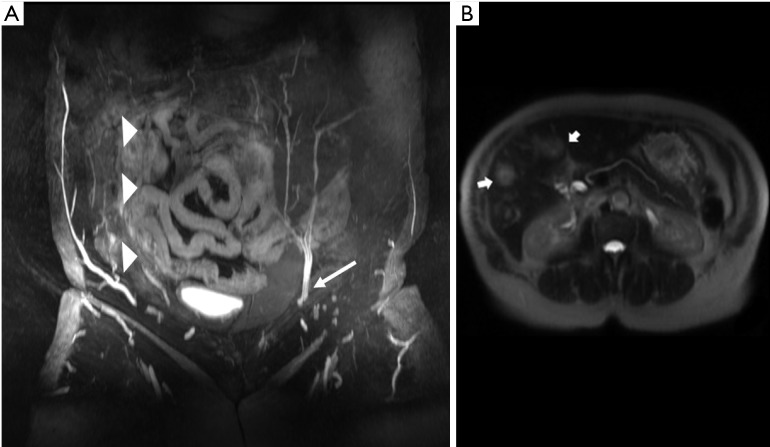
It is well established that free flap surgeries benefit from preoperative mapping of the vascular anatomy to plan the details of the surgery (6,7). Accurate identification of perforators facilitates preoperative decision making, as harvesting perforator flaps is a complex operation with little room for error. Preoperative knowledge of the location of dominant perforators lessens the anxiety associated with surgery and increases surgeon’s confidence, as well as assists in mastering the complicated microsurgery in a very short time. Apart from assessing the patency of source vessels (Figure 1A), an additional advantage of preoperative imaging is screening for metastasis (Figure 1B) and other unexpected pathologies such as abdominopelvic masses or inflammation. It is not unusual that surgery is delayed or cancelled upon discovering incidental findings that change the course of clinical management of the patient; we have identified occult metastases in 4% of patients (8).
Figure 1.
Right deep inferior epigastric artery was injured during prior surgery and is occluded. Preoperative MRI was able to screen this and avoid an unnecessary surgery which would have led to flap failure. Preoperative images also screen for metastasis. In this case surgery is deferred and instead treatment for metastasis (chemotherapy) is started. (A) Right DIEA is completely obliterated (arrowheads) in a patient with prior surgery. Compare with patent DIEA on the left (arrow); (B) T2 intermediate intensity lesions in liver (arrows) concerning for metastasis in a patient with breast cancer. DIEA, deep inferior epigastric artery.
Several modalities are available for assessment of perforators. Preoperative modalities include hand held Doppler (HHD) assessment, color Doppler ultrasonography, CTA, MRA and dynamic infrared thermography (DIRT). The commonly used US, CTA and MRA techniques are described in detail below. DIRT technique uses the principle of surface cooling followed by a period of rewarming. As the tissues rewarm, an infrared camera analyzes the changes in cutaneous perfusion and localizes hot spots that correlate with the location of the perforating vessels. First appearing hot spots are confirmed to be arterial on Doppler and CTA. Perforators associated with rapid rewarming were more reliable than those associated with slow rewarming. DIRT has the benefit of no radiation or contrast agent exposure, and gives information on flow. However, hot spots on DIRT images were always slightly laterally located in relation to the exit points of the associated perforators through the rectus abdominis fascia on CTA. Another limitation is no information on perforator course is obtained. Hence the accuracy of perforator detection is considered moderate (9,10).
Laser-assisted indocyanine green fluorescence angiography (LA-ICGFA) utilizing IV injection of indocyanine green allows for direct visualization of perforator perfusion pre and intraoperatively. An image capturing device transmits the images of cutaneous territory to a computer that analyzes the data and generates the real-time images. ICGFA has the ability to assess perfusion at the distal most aspects of muscle and musculo-cutaneous flaps and can accurately predict the viability of skin flaps (11,12). This technique can be used as an adjunct to cross-sectional studies.
Near infrared (NIR) spectroscopy is used in a few centers for monitoring free flaps. In this technique, a flat surface probe is placed on the skin, which emits near-infrared light. This probe is able to detect the oxygen tension measurements and hemoglobin content in the surface vessels allowing for early diagnosis of altered perfusion (13).
Doppler ultrasonography
Ultrasound was the first tool that surgeons used for preoperative perforator mapping (10). Apart from providing information related to the location, size, and flow patterns of the perforators, information such as flow, direction, and velocity is also available, but operator dependent. HHD is easy to perform, does not need specialized expertise, easily available and is low cost. However, HHD can only detect vessels to a depth of 20 mm, which is a challenge in large patients and can underestimate the available perforator options (14).
Color Doppler ultrasound differentiates between venous and arterial signals. Heitland et al. reported perforator detection to be 96% effective with ultrasound (15). A limitation of color Doppler ultrasonography is that highly trained technologists with knowledge of perforator anatomy are required. In addition, the exam is time consuming, and anatomic images cannot be produced in a format that a non-radiologist can easily view and interpret. Other shortcomings include difficulty distinguishing large from small perforators, determining whether perforators arise from the superficial or deep system, and locating perforators that do not exit fascia perpendicularly, leading to relatively high number of false-positive and negative results (46%) (16).
CTA
Thin slice CTA has been a gold standard for preoperative imaging albeit with high radiation exposures. Additional benefits include wide availability, fast scanning, familiarity of most radiologists and surgeons with the modality, and overall accurate anatomic localization of the perforators. Limitations are the increased complexity of bolus timing and poor opacification of veins as well as a trend toward lower quality, grainier images when constraints are placed on how much radiation is allowed for performing CTA.
CTA technique
Detection of the smallest branches of the perforator arteries depends on proper acquisition of CT images. Due to the concern for ionizing radiation exposure, CTA uses low dose protocols which reduce radiation dose to the patient but have the potential to decrease image quality if image parameters are not optimized.
Patient preparation: 3D surface rendering is a huge benefit of cross-sectional imaging, every crease/impression on the skin is reflected on the final surface rendered image. Hence, the patient is asked to remove undergarments that may cause skin impressions, especially underwear. Patient should wear only the gown provided by the imaging center, and not tie knots that may compress an area of interest. For CTA, since the imaging can be accomplished in one breath hold, and the effect of breathing motion on abdomen and pelvis is minimal, patients are positioned supine with arms at their sides. This position also replicates the position on the operating room table during surgery.
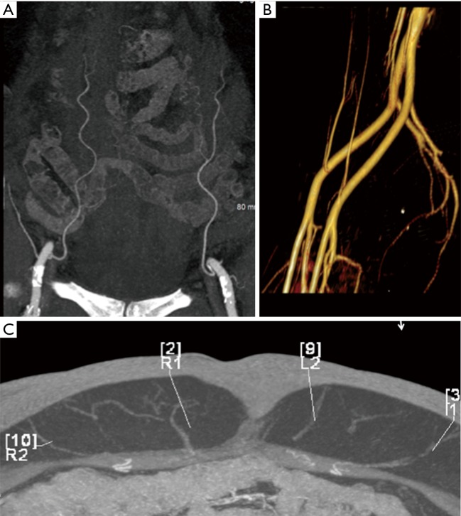
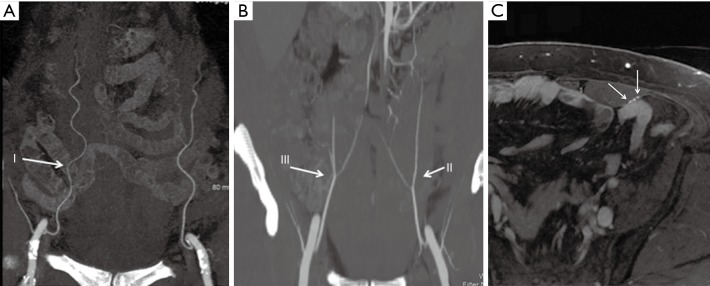
A large-gauge peripheral intravenous line is preferred in the antecubital region to allow rapid infusion of contrast for adequate opacification of small vessels. Approximately 1 to 2 g of iodine is injected per second with a flow rate of 4–6 mL/s to allow the best visualization of vessels with diameter between 1–4 mm. Using high iodine concentration contrast media (HCCM) to achieve high iodine flux contributes to improved diagnostic performance (17). Bolus triggering is performed in the thoracic aorta for craniocaudal scanning or the common femoral artery for caudal to cranial direction of scanning (Figure 2).
Figure 2.
CTA demonstrating patency of the deep inferior epigastric vessels on coronal MIP (A) volume rendered (B) and axial MIP (C) images. CTA, computed tomography angiography; MIP, maximum intensity projection.
To minimize radiation exposure, only the area of interest (from the origin of the inferior epigastric artery at the level of groin to a level approximately 4 cm above the umbilicus for DIEP flaps) is scanned. Most scanners today modulate the X-ray beam energy (defined as milliampere-second or mAs) based on the topogram obtained at the beginning of the examination or a similar algorithm. However, disabling this option has been reported by several investigators to improve delineation of the vessels of interest for DIEP flap CTA (18). Quality of imaging with visualization of vessels as small as 1 mm should be balanced with acceptable quantum noise levels. Reducing both tube current (mA) and tube voltage (kV) within clinical range will result in reductions in radiation dose; particularly, small reductions in kV have a more substantial effect on radiation dose reduction. Lower kVp values also lead to higher conspicuity of contrast media, especially when used with HCCM (19-21). Noise can be reduced by utilizing iterative reconstruction (IR) post processing techniques (22).
At our institution, all CTA exams are performed on a 64-slice scanner (Lightspeed VCT, GE, Waukesha, WI, USA). Scanning begins 3–4 cm above the umbilicus and extends down to the pubic symphysis with 0.625 mm slice thickness using a pitch of 0.9. Precontrast images are no longer acquired to limit radiation exposure; 100 mL of Omnipaque 350 is injected at 4 mL/sec. Postcontrast imaging is initiated 7–10 seconds after contrast arrival is detected in the distal thoracic aorta with blood attenuation of 240 Hounsfield units (HU).
MRA
MRA has lower spatial resolution but greater contrast resolution, which allows detection of the smallest perforators that stand out in a background of muscle or fat. Zou et al. reported that the qualitative image quality score based on vessel sharpness, vessel delineation and vessel visibility in relation to the background was higher for a blood pool MR contrast agent (gadofosveset) than an extracellular agent (gadobenate), and CTA (23). Therefore, MRA may be more accurate for tracing the intramuscular course of perforators compared to CTA (23-25) (Figure 3).
Figure 3.
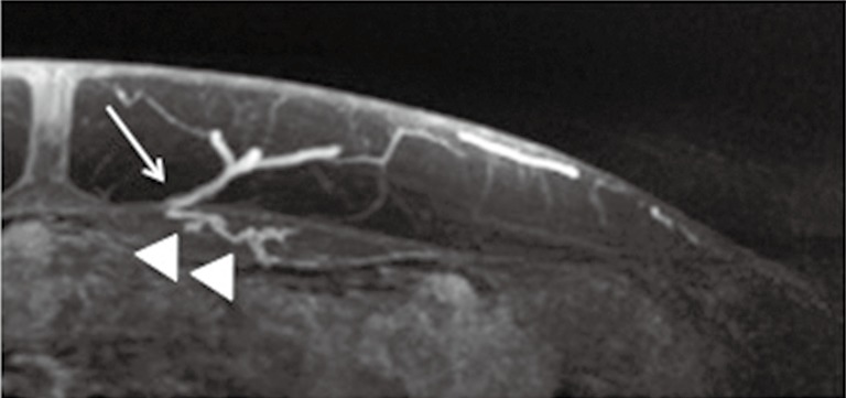
MRA due to its superior contrast resolution is excellent for evaluating the intramuscular course (arrow heads) and patency of perforators (arrow). MAR, magnetic resonance angiography.
The huge benefit of MRA is absence of ionizing radiation, which is especially relevant in younger patients who are more sensitive to carcinogenesis. The main limitation of MRA is that motion can affect visualization, especially if the sequences take longer than a normal breath hold. To minimize motion artifacts, patients are positioned prone and the phase encoding is set right-to-left to prevent motion artifacts dispersed in the phase direction from superimposing on the anterior abdominal wall soft tissues. MRA is also expensive, time consuming and more complicated to perform well and may not be offered at all MR imaging facilities. Patients with tissue expanders may not have access to MRA at facilities that are familiar with how to perform MR safely in such patients (8).
Gadolinium-based contrast agents used in MRI were recently shown to be deposited in the brain and were reported to induce persistent T1 shortening in deep gray matter structures even in subjects with normal renal function. However, there is no known disease associated with Gd deposition in the brain, and millions of patients with normal renal function have received GBCA without manifesting any related health problems. Based on literature and case reports published regarding Gadolinium deposition in brain, the U.S. Food and Drug Administration (FDA) is requiring a new class warning which includes explaining to patients that gadolinium can linger in the body and brain for months to years after receiving these drugs and adapting other safety measures. As gadolinium retention has not been directly linked to adverse health effects in patients with normal kidney function, and the FDA has concluded that the benefit of all approved GBCAs continues to outweigh any potential risks (26,27).
MRA technique
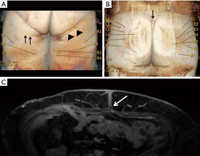
Similar to CTA patient preparation, the patients are asked to remove all clothing and especially undergarments that makes an impression on the skin (Figure 4A). Vitamin E capsules that are visible on MRA images are placed on surface landmarks that serve as reference points for calculating perforator location on images (e.g., umbilicus for DIEP flap, superior gluteal cleft for gluteal artery free flap, and inferior gluteal crease for PAP flap) (Figure 4B). As explained above, patients are positioned in the prone position to limit respiratory motion in the anterior abdominal soft tissues during preoperative imaging for the DIEP flap. The umbilical insertion to rectus sheath is stable in position in both prone and supine position, and this is used as reference point (Figure 4C). Axial images of the pelvis for PAP flap are also obtained in the same prone position, and in our experience, this does not distort the location of perforator arteries in relation to reference points (25).
Figure 4.
3D reconstructions of MRA images. (A) Undergarment impression (arrowheads) can distort the skin and cause displacement and errors in the position of skin coordinates for both the inferior gluteal crease reference point (arrows) and perforators; (B) to identify the skin landmarks on MRA images, a vitamin E capsule (arrow) is taped to the location on the patient’s skin; (C) umbilical fascial insertion to the rectus sheath is fixed, and the location does not change despite changes in patient position (arrow). MAR, magnetic resonance angiography.
Once the patient is positioned comfortably, the following sequences are obtained in order:
Three-plane localizer;
Axial and coronal fast T2 weighted sequences (SSFSE/HASTE) images are acquired next. These help to characterize any enhancing lesions incidentally seen on post contrast images. Incidental arterially enhancing and T2 intermediate lesions within the abdomen carry a high suspicion for metastasis in patients with history of breast cancer (Figure 1B);
Contrast enhanced high-resolution axial 3D LAVA/VIBE/THRIVE with fat saturation but without parallel imaging using the following approximate parameters: 4 ms TR/1.9 ms TE/15 flip angle, 512×512 matrix, 125 kHz or lower bandwidth, 3 mm section thickness reconstructed at 1.5 mm intervals using 2 fold zero interpolation (ZIP2). Phase encoding is set to the right to left (RL) direction to avoid phase artifacts overlapping on the anterior abdomen wall soft tissues. This is the primary sequence for reporting and generating reconstructions of the perforator vessels and also serves as a reference for the plastic surgeons. It is acquired with free breathing and typically requires 3–5 minutes. This scan is initiated simultaneously with beginning injection of 20 mL gadobenate dimeglumine at 1 mL/s followed by 30 mL saline flush at the same 1 mL/s injection rate;
Post Gd LAVA-flex, Dixon VIBE with similar imaging parameters as 3 above including 512×512 resolution. Echo times should ideally be in and out of phase which works well at 1.5T (2.1 and 4.2 ms) but can be more challenging at 3T (1.1 and 2.1 ms). This sequence is run with phase encoding set anterior to posterior for better visualization of the deep circumflex iliac perforators. This is particularly useful in the presence of tissue expanders which makes fat suppression less reliable;
Sagittal and coronal post contrast 3D SPGR with fat suppression at lower resolution are obtained with breath holding;
Additional axial high-resolution sequences of the second region of interest, for example MRI pelvis for a posterior thigh flap or chest for evaluating internal mammary vessels or thoracodorsal artery perforator (TDAP).
Post processing
Arterial phase images may also be obtained and can be reviewed to confirm patency of the DIEA and to evaluate the presence or absence of superficial inferior epigastric artery (SIEA). Equilibrium phase images (may not be available on CTA) are used for evaluating the deep inferior epigastric vein (DIEV) and superficial inferior epigastric veins. Since veins are more important that arteries with microvascular anastomoses, the MRA focuses on venous phases for evaluation of the artery/vein bundle.
Axial high spatial resolution images are loaded on a dedicated 3D post processing computer workstation (GE Advantage Windows 4.4, Milwaukee, WI, USA; Syngo.via Siemens Healthineers, Erlangen, Germany), which generates coronal, sagittal, and surface rendered 3D reformatted images. The area of interest extends from 4 cm above the level of umbilicus to about 10–15 cm below it. The coordinates for the reference point are noted first. Diameters and coordinates of 3–4 largest caliber perforator artery/vein bundles at the site of exit from rectus fascia to subcutaneous fat are noted. The location of the co-ordinates right/left or superior/inferior to reference point is then calculated manually. Alternately, Osirix/plugins developed specifically for perforator report creation can provide the same values (https://github.com/cjlange/pfara/releases) (28). In addition, automated methods can reduce transcription and measurement errors (28).
What makes a good perforator?
A desirable perforator has a feeding artery and vein that are patent along its entirety, do not demonstrate stenosis or discontinuity for at least 6 cm (and preferably 10 cm), has a diameter of at least 1 mm for the artery alone, has at least 2 mm total diameter for the artery-vein bundle, and has a short straight course through the underlying muscle for easy dissection (25).
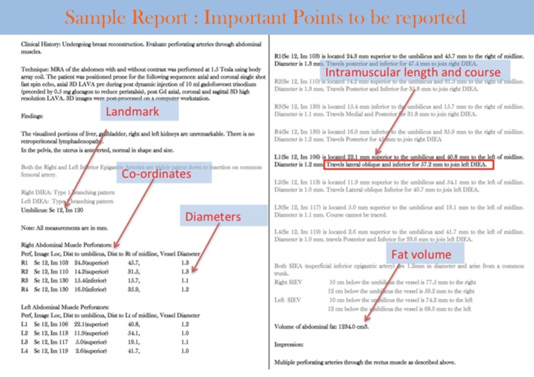
The goal of the perforator flap report is to assist surgeons to locate desirable perforators so they can pick optimum perforators (Figure 5) for sculpting the donor and recipient sites.
Figure 5.
Sample perforator flap report.
The components of the perforator flap report are:
Co-ordinates of the perforator in reference to the reference point which is clearly identifiable on the patient: the umbilicus for the DIEP flap, midpoint of the inferior gluteal crease for the PAP flap, or top of buttock crease for superior/inferior gluteal artery perforator flaps;
Perforator course described in a retrograde manner, to mimic the surgical dissection. For example, perforator course is described as “coursing posterior, lateral and inferior from the level of the anterior rectus sheath to insert into the DIEA”. Perforator course is also described as paramacular if the perforator courses around the muscle belly to join the main artery, intramuscular if the perforator courses through the muscle with a smooth or tortuous path. If there are alternate options, tortuous intramuscular perforators are usually avoided. The course and approximate length of the intramuscular course is described (Figure 5);
An estimate of a 13 cm × (36–42 cm) flap volume. This can be calculated manually on the computer workstation using 3D volume analysis software or using the plugin designed for this purpose (28);
For the benefit of the surgeons, 3D volume rendered images and a coronal 3D maximum intensity projection (MIP) image with superimposed locations of perforators are saved and referenced in the report. MIP images also demonstrate the branching pattern of the DIEA and profunda artery (Figure 5).
Deep inferior epigastric perforator flaps
This flap is usually the surgeon’s and the patient’s first choice because of the abundance of fat in the lower abdomen and large caliber DIEA perforators. Operational familiarity of the DIEP flap harvesting procedure, which is a modification of the original TRAM flap procedure familiar to many surgeons is another factor. Contraindications to DIEP flap are paucity of fat in this region, prior abdominal surgery which transects DIEP vessels as seen on CTA or MRA (Figure 1) or disruption of perforators by prior liposuction.
The inferior epigastric arteries are composed of a deep and superficial system. The deep system consists of the DIEA arising medially from the distal external iliac artery, immediately above the inguinal ligament, and ascending upward in the subperitoneal tissue. After piercing the transversalis fascia, it passes between the rectus abdominis muscle and the posterior rectus sheath. Three different DIEA branching patterns have been described: type I—a single trunk; type II—bifurcation into medial and lateral branches (most common); and type III—three or more branches (Figure 6A,B). The branching pattern leads to the arborization pattern of the flap (10). Depending on the branching pattern, multiple flaps can be harvested on the same side or alternate sides and stacked to form a larger stacked flap (29). Type II and III branching patterns give rise to medial and lateral row perforators. However, it should be noted that the medial row perforators may supply the subcutaneous fat across the midline, and caution should be exercised while planning a vertical oval flap. Each DIEA is accompanied by a pair of venae comitantes, usually with one vein on either side of the artery (Figure 6C).
Figure 6.
Branching pattern of DIEA and profunda femoris arteries. DIEA can arise as type I: common trunk (A), type II: bifurcate, or type III: trifurcate (B). Axial MRA images in equilibrium phase showing 2 vena comitantes (arrows) running on either side of deep inferior epigastric artery (C). DIEA, deep inferior epigastric artery; MAR, magnetic resonance angiography.
The SIEA arises from the common femoral artery 1–2 cm below the inguinal ligament and serves as an alternative to the DIEA. It passes superiorly and laterally through the femoral sheath to cross the inguinal ligament. Above the inguinal ligament, the SIEA passes between the layers of superficial fascia of abdominal wall, penetrates superficial fascia, and branches in the subcutaneous fat, anterior to the rectus sheath. The SIEA is absent in about one-third of patients and arises as a common trunk with the superior circumflex iliac artery in one third of patients. The common trunk variation is preferred as it provides a larger caliber vascular pedicle for microsurgical anastomosis (30). One benefit of using the SIEA is an easier dissection as it does not have an intramuscular course. However, the smaller caliber makes the vessel predisposed to perioperative thrombosis, and anastomosis with the internal mammary artery can be difficult. As a result, these flaps can be prone to necrosis from inadequate perfusion (31).
Another alternate flap in the lower abdominal region is the deep circumflex iliac artery perforator flap. The deep circumflex iliac artery perforator has a caliber similar to DIEA perforators and comes off the external iliac artery to supply the lateral abdominal skin and fat. The dominant perforator can be found 12 cm superior and 14 cm lateral to the anterior superior iliac spine (32). The scanning imaging coverage, position, and landmarks are the same as a DIEP flap; however, to minimize the lateral extent of bowel peristalsis motion artifacts, axial images are obtained with phase encoding set to anteroposterior direction. This technique is less commonly performed and less extensively studied but is slowly becoming popular. In patients with limited abdominal fat, a larger flap can be harvested if it is supplied by a DIEP in combination with a DCIP.
Venous anatomy
There is usually dominant drainage from the DIEV to the external iliac veins. In patients with small DIEV, there is dominance of superficial system, which in turn drains to the DIEV via perforator venae comitantes. DIEP flap reconstruction has a venous congestion rate of 6.3%. It is important to confirm that the superficial system is connected to the deep system before dissecting to prevent venous congestion (33). Atypical connections between veins increase risk of venous congestion fivefold (34). Preoperative imaging can detect non-communication or atypical connections between superficial and deep veins. Also, coordinate location of a large SIEV at 10 and 12 cm caudal to the umbilicus is mentioned in the report so that these are not inadvertently injured during incision.
PAP flap
A posterior thigh flap based on the PAP is the second most popular flap harvested and has almost replaced gluteal flaps as the alternative to abdominal flaps (5).
The reason for increasing popularity is that posterior thigh flaps are harvested with a patient in a supine position, with the legs in a frog leg position. Hence, there is no need to place the patient prone for flap dissection, and both flap harvesting and breast reconstruction in the chest can be performed in the same supine position, which saves intraoperative time, allows simultaneous procedures in the chest and posterior thigh, and reduces complications associated with prolonged operative time.
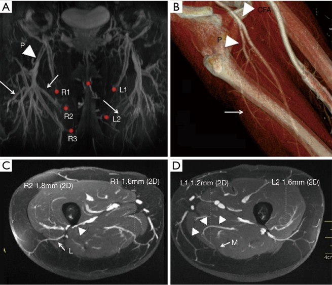
The profunda femoris artery comes off the common femoral artery and travels along the posterior compartment of the thigh. There are usually three main perforating branches which can be medial and/or lateral (Figure 7A,B) (35). Perforators that branch posterior-medially are preferred because these are easier to dissect in the supine frog leg position. Lateral perforators can course dangerously close to femoral shaft periosteum which is at high risk of injury during dissection (Figure 7C,D).
Figure 7.
Profunda femoral artery perforator anatomy. (A,B) Profunda femoris artery (P) after coming off the common femoral artery giving rise to perforating branches (arrows); (C) lateral branches of profunda femoral arteries (L) course immediately adjacent to periosteum and branch dissection may cause stripping of periosteum (arrowhead); (D) medial posterior thigh perforators (M) can have paramacular course (arrow heads) and are easier to dissect.
The inferior gluteal crease is the landmark for calculating coordinates for the PAP flap. The patient is ideally placed prone as this causes less distortion of the posterior thigh fat. This may not be possible in CTA where the abdomen and posterior thigh are often scanned simultaneously. Coverage extends from mid buttock to approximately 12 cm below the inferior gluteal crease.
The coordinates are calculated in reference to the inferior most point of the gluteal crease and lateral to an imaginary line drawn across the medial border of the thigh. The perforator branches of the inferior gluteal arteries are sometimes present inferior to the gluteal crease, and one of the biggest advantages of preoperative imaging is to identify these and report the coordinates so that the surgeons will carefully avoid them during surgery. The dissection of these perforators involves dissection deep into the gluteal region which can cause of complications.
A predicted flap volume is calculated by manual tracing an elliptical shaped pattern from the inferior gluteal crease to 6 cm caudally, and about 20–22 cm in the transverse dimension, again by utilizing manual or automated methods.
A lateral portion of the upper thigh flap can be supplied by lateral circumflex femoral artery perforators where the perforators course around the tensor fascia lata muscle (36). The location of these perforators is calculated in reference to umbilicus and pubic tubercles as reference points.
Conclusions
CTA and MRA preoperatively map perforators allowing surgeons to counsel patients accurately for realistic options regarding free flap breast reconstruction donor site selection and outcomes. Both CTA and MRA help greatly in the overall safety of intraoperative surgical dissection reducing operating room time and post operative complications. MRA is generally preferred over CTA in many places due to radiation concerns, better visualization of the perforator intramuscular course, and lack of iodinated contrast use. When MRA is not available or contraindicated, CTA, which is more widely available, can provide similar information, and has the advantage of greater familiarity with surgeons and radiologists worldwide.
Acknowledgments
None.
Footnotes
Conflicts of Interest: The authors have no conflicts of interest to declare.
References
- 1.Breast Reconstruction Surgeries After Mastectomies Increased More Than 60 Percent from 2009 to 2014. Available online: https://www.ahrq.gov/news/newsroom/press-releases/breastreconstruct1010.html
- 2.2016 Reconstructive Breast Procedures. Available online: https://www.plasticsurgery.org/documents/News/Statistics/2016/reconstructive-breast-procedures-age-2016.pdf
- 3.Available online: https://www.fda.gov:80/FDAgov/MedicalDevices/ProductsandMedicalProcedures/ImplantsandProsthetics/BreastImplants/ucm239996.htm
- 4.Leberfinger AN, Behar BJ, Williams NC, et al. Breast Implant-Associated Anaplastic Large Cell Lymphoma: A Systematic Review. JAMA Surg 2017;152:1161-8. 10.1001/jamasurg.2017.4026 [DOI] [PubMed] [Google Scholar]
- 5.2008 Reconstructive Breast Patients. Available online: https://www.plasticsurgery.org/documents/News/Statistics/2008/reconstructive-breast-procedures-age-2008.pdf
- 6.Wade RG, Watford J, Wormald JCR, et al. Perforator mapping reduces the operative time of DIEP flap breast reconstruction: A systematic review and meta-analysis of preoperative ultrasound, computed tomography and magnetic resonance angiography. J Plast Reconstr Aesthet Surg 2018;71:468-77. 10.1016/j.bjps.2017.12.012 [DOI] [PubMed] [Google Scholar]
- 7.Fitzgerald O’Connor E, Rozen WM, Chowdhry M, et al. Preoperative computed tomography angiography for planning DIEP flap breast reconstruction reduces operative time and overall complications. Gland Surgery 2016;5:93-8. [DOI] [PMC free article] [PubMed] [Google Scholar]
- 8.Thimmappa ND, Prince MR, Colen KL, et al. Breast Tissue Expanders with Magnetic Ports: Clinical Experience at 1.5 T. Plast Reconstr Surg 2016;138:1171-8. 10.1097/PRS.0000000000002782 [DOI] [PubMed] [Google Scholar]
- 9.Weum S, Mercer JB, de Weerd L. Evaluation of dynamic infrared thermography as an alternative to CT angiography for perforator mapping in breast reconstruction: a clinical study. BMC Med Imaging 2016;16:43. 10.1186/s12880-016-0144-x [DOI] [PMC free article] [PubMed] [Google Scholar]
- 10.Nahabedian MY. Overview of perforator imaging and flap perfusion technologies. Clin Plast Surg 2011;38:165-74. 10.1016/j.cps.2011.03.005 [DOI] [PubMed] [Google Scholar]
- 11.Pestana IA, Coan B, Erdmann D, et al. Early experience with fluorescent angiography in free-tissue transfer reconstruction. Plast Reconstr Surg 2009;123:1239. 10.1097/PRS.0b013e31819e67c1 [DOI] [PubMed] [Google Scholar]
- 12.Komorowska-Timek E, Gurtner GC. Intraoperative perfusion mapping with laser-assisted indocyanine green imaging can predict and prevent complications in immediate breast reconstruction. Plast Reconstr Surg 2010;125:1065. 10.1097/PRS.0b013e3181d17f80 [DOI] [PubMed] [Google Scholar]
- 13.Keller A. A new diagnostic algorithm for early prediction of vascular compromise in 208 microsurgical flaps using tissue oxygen saturation measurements. Ann Plast Surg 2009;62:538-43. 10.1097/SAP.0b013e3181a47ce8 [DOI] [PubMed] [Google Scholar]
- 14.Shaw RJ, Batstone MD, Blackburn TK, et al. Preoperative Doppler assessment of perforator anatomy in the anterolateral thigh flap. Br J Oral Maxillofac Surg 2010;48:419-22. 10.1016/j.bjoms.2009.08.016 [DOI] [PubMed] [Google Scholar]
- 15.Heitland AS, Markowicz M, Koellensperger E, et al. Duplex ultrasound imaging in free transverse rectus abdominis muscle, deep inferior epigastric artery perforator, and superior gluteal artery perforator flaps: early and long-term comparison of perfusion changes in free flaps following breast reconstruction. Ann Plast Surg 2005;55:117-21. 10.1097/01.sap.0000168690.00981.27 [DOI] [PubMed] [Google Scholar]
- 16.Giunta RE, Geisweid A, Feller AM. The value of preoperative Doppler sonography for planning free perforator flaps. Plast Reconstr Surg 2000;105:2381-6. 10.1097/00006534-200006000-00011 [DOI] [PubMed] [Google Scholar]
- 17.Contrast Optimization in Low Radiation Dose Imaging Available online: https://www.appliedradiology.org/courses/3068%2FPDF%2FAR_HCCM_0716_Supplement.pdf
- 18.Alonso-Burgos A, García-Tutor E, Bastarrika G, et al. Preoperative planning of deep inferior epigastric artery perforator flap reconstruction with multislice-CT angiography: imaging findings and initial experience. J Plast Reconstr Aesthet Surg 2006;59:585-93. 10.1016/j.bjps.2005.12.011 [DOI] [PubMed] [Google Scholar]
- 19.Furuta A, Ito K, Fujita T, Koike S, et al. Hepatic enhancement in multiphasic contrast-enhanced MDCT: Comparison of high- and low-iodine concentration contrast medium in same patients with chronic liver disease. AJR Am J Roentgenol 2004;183:157-62. 10.2214/ajr.183.1.1830157 [DOI] [PubMed] [Google Scholar]
- 20.Rau MM, Setty BN, Blake MA, et al. Evaluation of renal transplant donors with 16-section multidetector CT angiography: comparison of contrast media with low and high iodine concentrations. J Vasc Interv Radiol 2007;18:603-9. 10.1016/j.jvir.2007.02.016 [DOI] [PubMed] [Google Scholar]
- 21.Bae KT. Intravenous contrast medium administration and scan timing at CT: Considerations and approaches. Radiology 2010;256:32-61. 10.1148/radiol.10090908 [DOI] [PubMed] [Google Scholar]
- 22.Corcuera-Solano I, Doshi AH, Noor A, et al. Repeated head CT in the neurosurgical intensive care unit: feasibility of sinogram-affirmed iterative reconstruction-based ultra-low-dose CT for surveillance. Am J Neuroradiol 2014;35:1281-7. 10.3174/ajnr.A3861 [DOI] [PMC free article] [PubMed] [Google Scholar]
- 23.Zou Z, Kate Lee H, Levine JL, et al. Gadofosveset trisodium-enhanced abdominal perforator MRA. J Magn Reson Imaging 2012;35:711-6. 10.1002/jmri.22853 [DOI] [PubMed] [Google Scholar]
- 24.Agrawal MD, Thimmappa ND, Vasile JV, et al. Autologous breast reconstruction: preoperative magnetic resonance angiography for perforator flap vessel mapping. J Reconstr Microsurg 2015;31:1-11. [DOI] [PubMed] [Google Scholar]
- 25.Thimmappa ND, Vasile JV, Ahn CY, et al. MRA of the skin: mapping for advanced breast reconstructive surgery. Clin Radiol 2019;74:13-28. 10.1016/j.crad.2017.12.018 [DOI] [PubMed] [Google Scholar]
- 26.Tedeschi E, Caranci F, Giordano F, et al. Gadolinium retention in the body: what we know and what we can do. Radiol Med 2017;122:589-600. 10.1007/s11547-017-0757-3 [DOI] [PubMed] [Google Scholar]
- 27.FDA Drug Safety Communication: FDA warns that gadolinium-based contrast agents (GBCAs) are retained in the body; requires new class warnings. Available online: https://www.fda.gov/Drugs/DrugSafety/ucm589213.htm
- 28.Lange CJ, Thimmappa ND, Boddu SR, et al. Automating perforator flap MRA and CTA reporting. J Digit Imaging 2017;30:350-7. 10.1007/s10278-017-9943-z [DOI] [PMC free article] [PubMed] [Google Scholar]
- 29.DellaCroce FJ, Sullivan SK, Trahan C. Stacked deep inferior epigastric perforator flap breast reconstruction: A review of 110 flaps in 55 cases over 3 years. Plast Reconstr Surg 2011;127:1093-9. 10.1097/PRS.0b013e318205f223 [DOI] [PubMed] [Google Scholar]
- 30.Fukaya E, Kuwatsuru R, Iimura H, et al. Imaging of the superficial inferior epigastric vascular anatomy and preoperative planning for the SIEA flap using MDCTA. J Plast Reconstr Aesthet Surg 2011;64:63-8. 10.1016/j.bjps.2010.03.012 [DOI] [PubMed] [Google Scholar]
- 31.Coroneos CJ, Heller AM, Voineskos SH, et al. SIEA versus DIEP arterial complications: a cohort study. Plast Reconstr Surg 2015;135:802e-7e. 10.1097/PRS.0000000000001150 [DOI] [PubMed] [Google Scholar]
- 32.Buchel E. Deep circumflex iliac artery perforator flap for breast reconstruction. In: Levine JL, Vasile CM, Chen J, et al. (eds). Perforator flaps for breast reconstruction. New York: Thieme, 2016. [Google Scholar]
- 33.Kim DY, Lee TJ, Kim EK, et al. Intraoperative venous congestion in free transverse rectus abdominis musculocutaneous and deep inferior epigastric artery perforator flaps during breast reconstruction: a systematic review. Plast Surg (Oakv) 2015;23:255-9. [PMC free article] [PubMed] [Google Scholar]
- 34.Davis CR, Jones L, Tillett RL, et al. Predicting venous congestion before DIEP breast reconstruction by identifying atypical venous connections on preoperative CTA imaging. Microsurgery 2019;39:24-31. 10.1002/micr.30367 [DOI] [PubMed] [Google Scholar]
- 35.Ahmadzadeh R, Bergeron L, Tang M, et al. The posterior thigh perforator flap or profunda femoris artery perforator flap. Plast Reconstr Surg 2007;119(:194-200. [DOI] [PubMed]
- 36.Tuinder SMH, Beugels J, Lataster A, et al. The Lateral Thigh Perforator Flap for Autologous Breast Reconstruction: A Prospective Analysis of 138 Flaps. Plast Reconstr Surg 2018;141:257-68. [DOI] [PubMed] [Google Scholar]


