Abstract
Imaging is needed for diagnosis, treatment planning, and follow-up of patients with pathologies affecting upper extremity vasculature. With growth and evolution of imaging modalities [especially CT angiography (CTA) and MR angiography (MRA)], there is need to recognize the advantages and disadvantages of various modalities and obtain the best possible imaging diagnostic test. Understanding various limitations and pitfalls as well as the best practices to minimize and manage these pitfalls is very important for the diagnosis. This article reviews the upper extremity arterial vascular anatomy, discusses the CTA and MRA imaging, various pitfalls, and challenges and discuss imaging manifestations of upper extremity arterial pathologies.
Keywords: Imaging, CT angiography (CTA), MR angiography (MRA), trauma, vasculitis, upper extremity, thoracic outlet syndrome (TOS), injury
Introduction
Upper extremity vascular abnormalities are near universally evaluated by multi-modality imaging. It may be affected by various pathologies ranging from acute traumatic injuries to chronic atherosclerotic disease. In the current scenario of non-invasive imaging, modalities like CT and MRI have found their niche with CT angiography (CTA) and MR angiography (MRA). Traditionally, digital subtraction angiography (DSA) of vascular arterial abnormalities of the upper extremity has been the primary imaging modality for vascular assessments because of its higher spatial resolution and still remains the gold-standard. However, with the technical advances of CTA and MRA as well as 3D reconstructions, there has been a significant increase in considering these imaging modalities for assessment of vascular pathologies and are replacing DSA as a pure diagnostic imaging modality (1,2).
The choice between the CT and MR imaging techniques as a cross-sectional imaging modality of choice depends upon the indication and urgency of the study. Traditionally, CTA has been the imaging modality in emergency settings like trauma, dissections or embolism and MRA is the preferred modality for non-urgent conditions like congenital, inflammatory or to characterize soft tissue anatomy (3,4). With relative risks of iodinated contrast and radiation, there has been an increase in trend for MRA as a preference of imaging modality for semi-urgent conditions, long-term follow-up, the ability for better soft tissue characterization without radiation and better evaluation of venous and neurological compression. In this review, we discuss the upper extremity vascular anatomy, various imaging modalities (focusing on CTA and MRA), challenges and pitfalls of the upper extremity imaging and key imaging features of some of the common and uncommon vascular pathologies of upper extremity.
Normal and variant anatomy
Inflow arteries
The inflow vessels to the upper extremity include the aortic arch, brachiocephalic, and subclavian arteries (5). Although in the majority of people the aortic arch has the usual 3-vessel configuration comprising of the brachiocephalic, left carotid, and left subclavian arteries, it demonstrates anatomical variations in some cases. The most common arch variant is the common origin of the brachiocephalic artery and left carotid artery that may be seen in approximately 5–15% of patients (6). The vessels beyond the level of the subclavian artery are the outflow vessels (5).
Outflow arteries
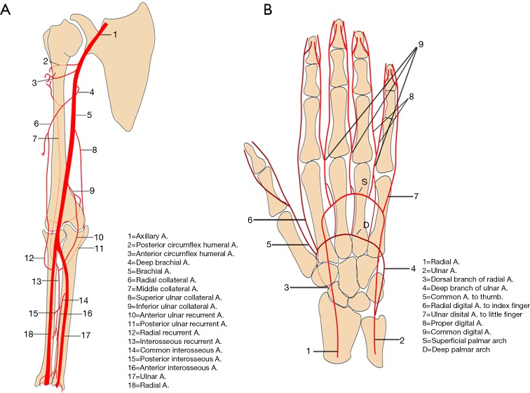
These include the axillary, radial, brachial, and ulnar arteries (Figure 1). Anatomically, the subclavian artery becomes the axillary artery at the lateral margin of the first rib. The branches of axillary artery supply blood to muscles of the shoulder girdle, humerus, scapula, and chest wall. After coursing beyond the inferior lateral margin of the teres major muscle, the axillary artery becomes the brachial artery.
Figure 1.
Graphical images of the arm and forearm (A) and hand (B) showing normal vasculature and their major branches. Reproduced with permission from (5).
The brachial artery divides into the radial and ulnar arteries. The anatomical bifurcation point of the brachial artery is also the most common site for upper extremity emboli to lodge, most of which are cardiac in origin (7). In approximately 15–20% of cases, the bifurcation may be high in the arm (Figure 2) or the axilla, which may contribute to slow maturation of dialysis fistula (8). The radial artery courses along the radial side of the forearm to the wrist, traverses the snuffbox, and turns medially to give rise to the deep palmar arch.
Figure 2.
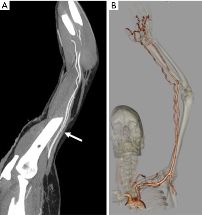
A 36-year-old man with numbness of the ulnar aspect of the hand. CT angiography reconstructed maximum intensity (A) and volume rendered (B) projection showing incidentally noted high bifurcation (white arrow) of the brachial artery into radial and ulnar artery in the mid-arm.
Anatomical variations in the ulnar artery and its branches are rare. At the level of the wrist, the ulnar artery gives off the dorsal branch and then runs in the Guyon canal (a fibro-osseous tunnel formed by the pisiform, hamate, and carpal ligaments). The distal ulnar artery divides into the superficial and deep branch just distal to the level of pisiform bone. The superficial branch continues into the superficial palmar arch and contributes the majority of blood supply to the fingers. The smaller deep branch anastomoses with the deep palmar arch. The persistent median artery is a rare variant in which the embryonic median artery fails to regress. It is important to recognize this variant because of its association with carpal tunnel syndrome, pronator syndrome, operative complications, and other vascular variations in the arches of hand. It typically arises from the ulnar artery or its interosseous branches and follows the course of the median nerve in the forearm to form a medio-ulnar type of superficial palmar arch in the hand.
Vascular arches of the hand
In hand, two palmar arches (superficial and deep palmar arch, Figure 1) can be evaluated by cross-sectional imaging. The superficial palmar arch is the dominant blood supply to the hand and is formed predominantly by the ulnar artery, with a small contribution from the superficial palmar branch of the radial artery. It is the distal-most arch and is located overlying the diaphysis of the metacarpals. The superficial arch has been described as complete in approximately 70% of cases (9). The deep palmar arch is formed by the anastomosis of the terminal part of the radial artery with the deep palmar branch of the ulnar artery and is less prone to anatomical variations. The deep palmar arch is located on the base of the metacarpals. The superficial palmar arch gives off three common palmar digital arteries, and the deep arch gives off three palmar metacarpal arteries. These branches anastomose in the interosseous space then divide into proper palmar digital arteries. The thumb and radial side of the second finger are supplied directly from the deep palmar arch, by the princeps pollicis and the radialis indicis arteries, whereas the ulnar side of the fifth finger is supplied directly by a proper digital artery from the superficial palmar arch. The understanding and imaging of these vascular arches can be helpful for diagnosis of hand pathologies and to guide various interventions like trans-radial or trans-ulnar catheterization, hemodialysis, or coronary artery bypass grafting (9).
Imaging techniques
Appropriate clinical history and physical examination play an important role to decide the best imaging modality and to modify the imaging protocol. Various imaging modalities for evaluation of upper extremity vasculature include Ultrasound and Color Doppler, CTA, MRA, and DSA. The advantages and disadvantages of various imaging modalities used for evaluation of upper extremity vasculature are highlighted in Table 1. DSA has maintained its place as the gold standard for imaging for upper extremity vascular imaging due to its high resolution as well as advantages for treatment at the same time though there is enough evidence for CTA as the diagnostic test of choice for upper extremity arterial evaluation (10).
Table 1. Advantages and disadvantages of various techniques used for upper extremity imaging.
| Modality | Advantages | Disadvantages |
|---|---|---|
| US-Doppler | Real-time | Operator dependence |
| Portable, fast exam | Limited windows, angles, and depth of access | |
| Applicable in nearly all cases | Relatively low spatial resolution—1–2 mm | |
| Flow velocity assessment | Artefacts in spectral and color Doppler | |
| No ionizing radiation | ||
| CT | Non-invasive technique | No real-time flow velocity or volume assessment |
| Easy accessibility | Uses ionizing radiation | |
| Quick examination | Limited use in patients allergic to contrast and in renal failure | |
| High spatial resolution (0.6–0.7 mm) | Technical challenges with motion and beam hardening artefacts especially with severely calcified arteries | |
| Less operator dependent | ||
| Simultaneous evaluation of central vessels, soft tissues and osseous structures | ||
| MRI | High accuracy and reproducibility | Limited availability and costly |
| Simultaneously assessment of central vessels and soft tissues. | Long exam time requiring patient compliance to remain still during examination | |
| No ionizing radiation | Low spatial resolution (through-plane =6–8 mm) | |
| Artifacts | ||
| Limited use in patients with most pacemakers or implantable cardioverter defibrillators | ||
| DSA | High accuracy | Invasive |
| Highest temporal resolution | Uses ionizing radiation | |
| High spatial resolution | Limited possibility in patients allergic to contrast and in renal failure | |
| Potential of simultaneous intervention | Limited availability | |
| Required expertise |
Color Doppler and vascular ultrasound are used as an initial screening modality and have many advantages, like wide availability, portability and ability to do a bed-side cost-effective exam. Vessel wall, lumen pathologies, and flow dynamics can be assessed with vascular ultrasound and Color Doppler. Few disadvantages include its operator dependence, inability to assess central vessels especially in obese patients or with extensive superficial injuries. Also, it can be time-consuming if there is any variant anatomy.
CTA is the most common imaging modality utilized in the evaluation of upper extremity acute trauma or acute occlusion (5). Its status as a first-line imaging modality for upper extremity is due to faster scan times, easy and round the clock availability, evaluation of concurrent osseous and soft tissue injuries, familiarity by surgeons as well as radiologists. A focused history to identify any possible contraindication to intravenous (IV) iodinated contrast administration from every patient should be obtained. CTA may not be possible in the presence of absolute contraindication (like severe iodinated contrast allergy or acute kidney injury) and other imaging modalities should be sought after. In case of relative contraindications, patient preparation should be performed as per the ACR contrast manual (11). Patients should be well hydrated prior to CTA. A 20 gauge or larger IV cannula should be placed on the non-affected side in the antecubital fossa or forearm. If both arms are affected a central venous access should be used. Power injector with a saline chase is required. CTA protocol positioning for upper extremity vascular imaging for non-traumatic etiology ideally include supine positioning, with the affected arm positioned raised over the head (Figure 3), with hand placed in anatomical position with palm facing ventrally, and fingers straight and extended. Prone positioning can also be performed with arms up and palm facing the table if that is more comfortable for a particular patient. In trauma patients, scanning is performed with patients arms by the side (Figure 3). The extremity to be scanned should be supported using wedges, pillows for immobilization. The CTA protocol is detailed in Table 2. Special scanning is performed in patients with thoracic outlet syndrome (TOS), where functional analysis is needed. First a set of scanning is performed while replicating Adson maneuver (arm abducted in external rotation and head turned to the same side) and then second set of scanning is performed in neutral position only if the first set is positive for vascular compression at the thoracic outlet (2). Novel techniques like dual energy CTA have revolutionized CT technique by lowering contrast media volume to up to 0.75 mL/kg (12).
Figure 3.
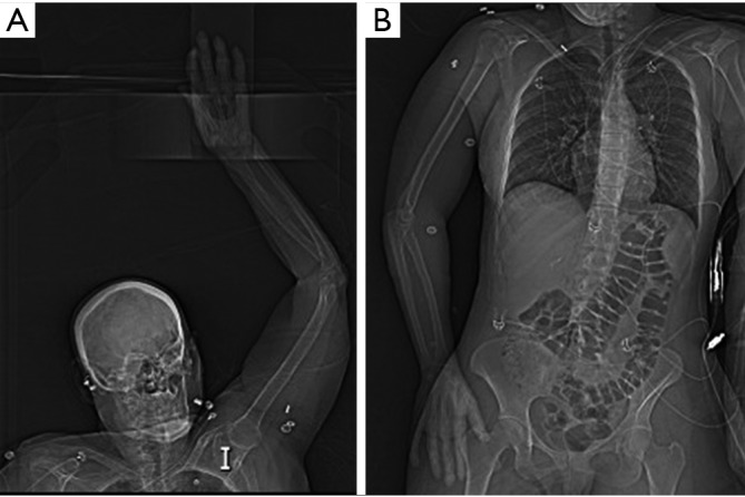
Topogram images showing preferred supine positioning with affected arm raised overhead (A). In trauma patients (or other patients) unable to position arm overhead, imaging can be performed with affected arm by patient’s side (B).
Table 2. CT angiography protocol for upper extremity pathologies.
| Parameter | Details |
|---|---|
| Position | Extremity of interest over the head with the palm ventral and fingers extended and straightened (whenever possible) |
| Scan range | Carina to fingertips |
| Delayed scan | Just above elbow to fingertips |
| Trigger | Bolus tracking, trigger at aortic arch (180 HU) or manual trigger immediately at opacification of brachial artery in mid arm |
| Contrast agent | Iopamidol 370 mg/mL (Bracco Diagnostic, Princeton, NJ), preferably inject in the non-affected extremity |
| Amount and rate | 100–125 mL at 5 cc/s |
| Saline flush | 40 mL at 4 cc/s |
| Slice thickness | 1 mm with 0.7 mm reconstruction interval |
| Window width/window level | 600/80 |
| Pitch | Variable |
Reprinted with permission from (5).
MRA has evolved over a few past decades and is extremely useful due to lack of ionizing radiation and iodinated contrast medium. Due to its high contrast resolution, MRA provides excellent image quality (3). MRA is extremely useful in disorders such as hypothenar hammer syndrome, Raynaud’s syndrome, thromboangiitis obliterans, as well as disorders requiring multiple follow up imaging evaluations. Functional evaluation of certain disorders like Raynaud’s syndrome or TOS is possible with MRA. MRA can be performed without or with the use of IV gadolinium-based contrast agents (GBCA). Non-contrast MRA is mainly performed using time of flight (TOF) and phase contrast (PC) that use dynamic flow characteristics of flowing blood (13). Other newer techniques include quiescent-interval single-shot (QISS), arterial spin labeling, flow-sensitive dephasing (FSD) and EKG-gated balanced steady-state free precession (14). Disadvantages of non-contrast MRA include overestimation of the degree of stenosis in cases of abnormal blood flow or complex anatomy and limited ability to visualize peripheral vasculature. QISS MRA can visualize peripheral vasculature with sensitivity similar to contrast-enhanced MRA but has significantly less specificity (15). FSD MRA involves inducing arterial flow voids at systolic cardiac phase while having little effect on venous blood and static tissues. High-spatial-resolution MRA is obtained by means of magnitude subtraction between a dark-artery scan with FSD preparation at systole and a bright-artery scan without FSD preparation at mid-diastole. FSD MR angiographic technique does not rely on the inflow effect and enables arterial visualization with high isotropic spatial resolution and excellent contrast between arteries and surrounding veins and tissues without the use of contrast material. Therefore, it may be suited for imaging tortuous and small hand arteries with substantially slow flow (16).
Contrast-enhanced MRA utilizes IV GBCA, is less time consuming, has a high spatial resolution, and is a more reliable method. Time-resolved MRA has a high temporal resolution and can help to evaluate arterial to venous shunting as well as evaluation of collateral pathways in cases of stenosis. Patient positioning and comfort is the key to excellent imaging in MRA. Patients are imaged in the supine position with arm by the side for arm imaging. For forearm and hand imaging patient is placed in superman position (prone with arm extended over the head). The MRA protocol is detailed in Table 3.
Table 3. MR angiography protocol for upper extremity pathologies.
| Parameter | Details |
|---|---|
| Position | Hand and forearm: “superman” position (prone with arms extended) |
| Arm and inflow vessels: supine with arm to the side in anatomical position | |
| Suspected thoracic outlet syndrome: 2-phase examination (overhead and externally rotated arm positioning followed by neutral arm positioning) | |
| Coil | Multichannel phased-array coil/extremity coil |
| Contrast agent | Gadobenate dimeglumine (Multihance, Bracco Diagnostic, Princeton, NJ) |
| Dose | 0.1 mmol/kg |
| Technique | Coronal ultrafast spin echo (Siemens—HASTE) of upper chest and the extremity. |
| Split bolus contrast injection: 5 cc—TWIST sequence for hand; 5 cc MRA of distal arm and forearm; rest of contrast bolus split between MRA of aortic arch with proximal arm and the anatomical area of interest | |
| 3D MRA using a 3D gradient-echo pulse sequence with fat suppression—anatomical area of interest. | |
| Ultrafast gradient-echo post-contrast T1 sequence (Siemens—VIBE) of chest and arm in axial and coronal plane | |
| Contrast injection rate | 1.5–2 mL/s |
| Saline flush | 20 mL at 2 mL/s |
Reprinted with permission from (5). HASTE, half-Fourier acquisition single-shot turbo spin echo; VIBE, volumetric interpolated breath-hold examination.
Challenges in upper extremity imaging
For a successful interpretation of an imaging test, the study quality is paramount. The quality is directly influenced by the presence or absence of artifacts or pitfalls, which form the most important challenges encountered during the study. These challenges, particularly in the upper extremity imaging need to be managed meticulously to obtain best-optimized imaging. Overall these challenges can be broadly classified as the patient related and technical related factors and are interdependent of each other (2).
Technical factors
There are various technical related factors affecting the enhancement of the image like the rate of contrast injection, the concentration of the contrast medium used, the timing of the scan, the table speed, the radiation dose, and the pitch of the scan. There are also some other independent factors in particularly affecting the upper extremity imaging like artifacts from the presence of a pacemaker, stents, lines, previous valve replacements and metallic artifacts from previous surgeries.
Vascular contrast factors affecting image quality
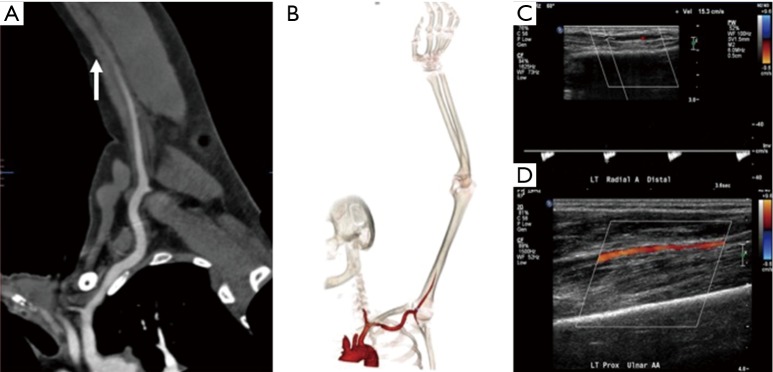
Contrast is the cornerstone of any angiographic study and is one of the most important factors to achieve good quality images. To achieve appropriate contrast enhancement, bolus tracking is typically used. In patients with suspected inflow disease, it is useful to perform manual trigger when contrast enhancement of brachial artery in mid-arm is seen (Figure 4). However, this requires precision and trained technologist or physician at the scanner. Also, this technique is not possible in patients with suspected embolic disease and brachial occlusion. An early scan trigger can lead to poor enhancement of the arteries and a delayed trigger can lead to venous contamination (Figure 5) and decreased arterial enhancement. A pre-planned second run may be useful in patients with proximal severe stenosis or near-total occlusion to evaluate slow or collateral flow to the distal vessels (Figure 6). But this comes at an expense of increased radiation dose. With dual-source scanners, reconstruction of low kV (like 40 kV) images can also help overcome limitations of poor contrast enhancement and enable low contrast dose imaging (12). Injection rate and timing of the contrast depends upon the size of the cannula. In practice a minimum size of a 20-gauge cannula in antecubital fossa, preferable in the non-imaged limb is ideal for good opacification of the vessels, to avoid any masking of pathology by streak artifacts with an aim to achieve a contrast flow rate of 4 to 6 mL per second. If however both the upper extremity imaging is required, then contrast injection through a central venous access, if available would be preferred (1). The contrast injection from the extremity of the interest can lead to extensive venous contamination and streak artifacts (Figure 7) which limits the evaluation of vessels. High BMI patients require a higher volume or concentration of the contrast and a higher injection rates which can influence the timing of the contrast and the phases of acquisition of images. If the pitch does not match the contrast injection rate and timing of the contrast within the vessels, can result in poor opacification of the vessels giving a false positive result (for occlusion or stenosis). The duration of injection should be calculated as a sum of both the scan time and the diagnostic delay if present to avoid any outrunning of contrast bolus.
Figure 4.
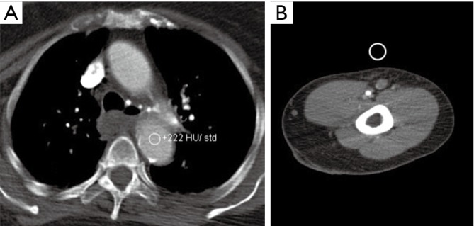
Monitoring options for bolus triggering for upper extremity CTA. Automated contrast bolus tracking technique at the level of aortic arch (A). In patients with suspected inflow disease, manual contrast tracking technique (B) is used in which scan is triggered when contrast enhancement of brachial artery in mid-arm is visually seen. CTA, CT angiography.
Figure 5.
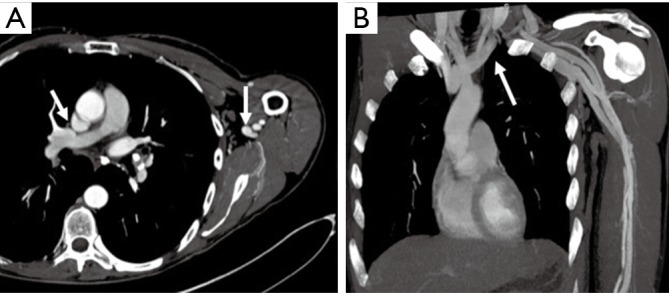
A 54-year-old man upper extremity CTA for evaluation of cold 4th and 5th digit. Axial (A) and coronal (B) CTA images with mispositioned automated bolus trigger window leading to scan delay and extensive central and peripheral venous contamination (arrows). CTA, CT angiography.
Figure 6.
A 62-year-old man with atrial fibrillation and cold left upper extremity. Curved reconstructed (A) and volume rendered (B) CT angiography images showing complete occlusion of the brachial artery in mid-arm (arrow) with non-enhancement of distal vessels. A delayed second run was not done and US Doppler images (C and D) showing slow flow in the distal vessels from collaterals or sub-total occlusion.
Figure 7.
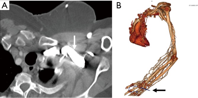
CT angiography images in a 48-year-old woman with suspected vasculitis. Axial image (A) showing streak artifacts from venous contrast (white arrow) limiting arterial evaluation. Volume rendered (B) showing severe venous contamination due to contrast injection from cannula (black arrow) in the left hand.
Radiation factors affecting image quality
Radiation dose also directly influences the image quality and depends upon the site examined and the BMI of the patient. In the context of upper extremity imaging, a higher dose of radiation is required for examination of large central vessels and in high BMI patients. The scanners typically select the kV and mA automatically based on patient’s BMI and topogram. However, in patients with stents, kV should be kept at least 100 to ensure adequate image quality. On CTA, these artifacts can also be potentially decreased by the use of wide bone window settings or use of sharp kernel instead of a smooth kernel reconstruction or edge enhancement filter. The noise from these techniques can be reduced by using interactive reconstruction (2,17,18).
Patient factors
Patients with contraindication to contrast agents
Allergic contrast reactions or other contraindications (like kidney injury) are other challenges for any vascular study. Contrast allergy can be related to iodinated contrast for CTA or GBCA for MRA. According to the ACR Manual on Contrast Media (11) adverse events to iodinated and gadolinium-based agents is more common in patients with prior reaction to MR agents or with a history of asthma (19-21). Allergy to contrast has a wide spectrum and can be classified as mild, moderate or severe. In the majority of mild and moderate cases of contrast allergy for CTA, patients can be premedicated with corticosteroids and antihistamines (21). Premedication for severe allergic reactions is a topic of debate. However, risk-benefit analysis should be done in patients with severe contrast reaction and in life-threatening situations. Steroid and antihistaminic premedication may be attempted for contrast reaction to old ionic-iodinated contrast with the availability of life-support apparatus and clinical team, depending on the institutional policy. Use of a different low-osmolality contrast agent in patients with documented reaction to another agent is also suggested, however in practice may provide little or no benefit (22,23). An alternative approach would be to change to another agent with pre-medication (23). ACR guidelines (11) suggest the use of serum creatinine and estimated glomerular filtration rate (eGFR) to evaluate for safe limits for the administration of contrast media. The evidence of any renal dysfunction from the iodinated contrast with eGFR >30 mL/min/1.73 m2 is lacking and is usually used as a safe limit for iodinated contrast administration (11). Similarly, for MRA contrast, the chances of nephrogenic systemic fibrosis (NSF) is negligible for eGFR >30 mL/min/1.73 m2 with only one reported case in a patient with eGFR >30 mL/min/1.73 m2 (11).
Patient compliance
Patient compliance is the most important factor directly responsible for a successful optimized study. Patients should be evaluated on compliance before a request is made for the examination. Evaluation should be carried out by both the clinical team and the radiology team before the patient is scanned. The patient should be instructed about the importance of lying still during the scan and a particularly comfortable position should be discussed and ability to hold breath during the scan checked in advance (2). In children, elderly, confused and non-co-operative patients, alternative imaging and/or imaging with anesthesia could be considered. With CT, use of high pitch leads to a faster scan and hence should be preferred in non-compliant patients. Preferred positioning with overhead affected extremity (Figure 3A) also helps to prevent streak artefact from patient’s chest and abdomen. Better quality images are obtained if the area of interest is close to the isocenter of the scanner without interference from non-relevant anatomy (1).
Body mass index (BMI) and heart failure
BMI and cardiac output of the patient also directly influence the trigger for enhancement and the injection rate used. For patients with increased BMI, higher contrast dose is useful to ensure appropriate enhancement of distal vasculature. With newer scanners, modification of parameters like kV and mA is not needed to prevent streak artifacts. Patients with heart failure require longer delayed scans while patients with hyperdynamic circulation from high output will require adequate contrast volume and injection rates to match the output with adequate opacification of examined vessels. In our experience, patients with mild to moderate heart failure do not need any change in the volume or rate protocol. In patients with severe heart failure (ejection fraction of ≤35%), test bolus technique using 15 mL of Iodinated contrast may be used to calculate the precise time to peak enhancement in patients with heart failure or hyperdynamic circulation rather than standard bolus-trigger technique, followed by angiogram of 60 mL of contrast making a total of 75 mL of contrast at a rate of 4–5 mL/sec, to ensure adequate enhancement of the vessels.
Vessel wall calcifications
Blooming artifacts from vascular calcifications can overestimate the degree of stenosis in CTA. Vascular calcifications in severe atherosclerosis can also significantly impair the inflow of contrast into the area of interest. This problem can be partially overcome by obtaining a non-contrast phase to see the calcium burden in the vessel and use of MRA as an alternative. Other physiological and pathological conditions that can directly influence the contrast flow and the quality of scan include hyperemic states like reperfusion injury post-ischemia or revascularization, high flow lesions, arteriovenous malformations (AVM), arteriovenous fistulas (AVFs), the presence of conduits or grafts. To overcome these challenges, use of certain maneuvers have been described in the past based upon the compliance of the patient like squeezing the ball prior to scanning to cause physiological hyperemia and warming the hand prior to scanning to distinguish between the vasospasm and true stenosis (1).
Pacemakers
Pacemakers are a potential challenge for upper extremity imaging. Safety of the device needs to be evaluated prior to the protocol. Device type and location constitute an important and major independent predictor of image quality and needs to be evaluated prior to and during protocol adaptation (24). Pacemaker artifacts appear as a signal void on MRA images (Figure 8) and lead to streaks on CTA. Pacemaker artifacts can be potentially reduced in both the CTA and MRA by physically moving the pacemaker partially out of the field manually and taping the skin using the adhesive tapes or by keeping the arm in hyper-abducted position.
Figure 8.
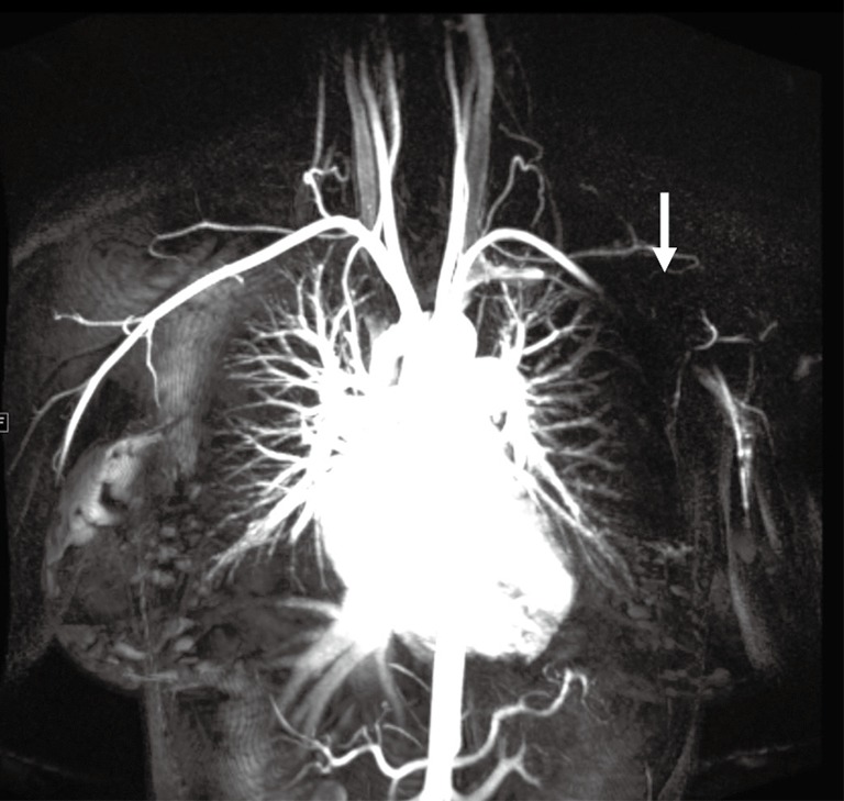
Coronal contrast-enhanced MR angiography image showing signal void (arrow) from a pacemaker in the left chest wall limiting evaluation of the distal subclavian and the axillary artery.
Upper extremity diseases
Acute trauma
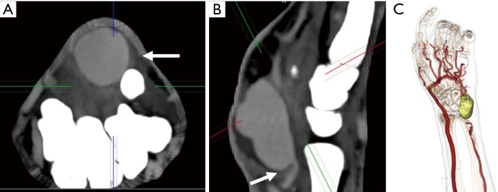
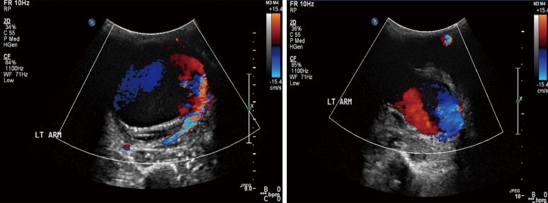
Trauma to the upper extremity can be divided into acute and chronic injuries for the purpose of imaging and management (25). CTA has taken over DSA as the imaging modality of choice for evaluation of suspected upper extremity trauma (10). Acute trauma can be penetrating (firearm injuries, sharp object related, iatrogenic) or non-penetrating (blunt blow). Another set of acute injuries can be related to acute exposure to chemicals, electrical currents or acute radiation (rare), all of which can result in occlusion and thrombosis. Most common upper extremity vessel involved in acute trauma is the brachial artery followed by the radial artery (4,5,26). The signs of arterial injury in a hemodynamically stable patient include pulselessness, acute neurological or muscular dysfunction, cool and/or discolored extremity (2). CTA sign of acute injury includes contrast media extravasation followed by local pooling of contrast (Figure 9), pseudoaneurysm (Figure 10), occlusion and AVF (Figure 11). Active arterial extravasation will show the spread of contrast media through various soft tissues on early as well as delayed phases and will have higher attenuation value than the affected artery on delayed phase. Multiple phases may be needed in cases of suspected pseudoaneurysm, arterial rupture, transection or AVF formation. Some indirect signs of injury to artery include a linear tract of contrast in the vicinity of a neurovascular bundle or a projectile within 5 mm of a suspected affected artery as well as hematoma formation. A pseudoaneurysm is defined as contained blood pooling due to rupture of vascular wall (27). The most common cause of an extremity pseudoaneurysm is trauma, but it can also be related to infection or prior interventions. It can be differentiated from extravasation using delayed phase imaging which will show pseudoaneurysm as a well-defined round to oval vascular structure which fills completely on delayed phase and will have attenuation similar to the blood pool phase (2,5,27). Point of care Color Doppler will show a classic “Yin Yang sign” (Figure 12) with to and fro waveform which is diagnostic of a pseudoaneurysm. Extrinsic compressions and spasms can be differentiated from transection, as the spasm usually open up on delayed phases. Also, there will be a smooth narrowing of the vessel in extrinsic compression while the occlusion is abrupt in transection (2,28). Arterial dissection will be seen as a linear filling defect within the lumen giving rise to a double lumen.
Figure 9.
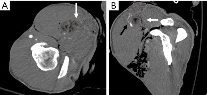
A 34-year-old man with a stab wound to the upper arm. Axial (A) and reconstructed sagittal (B) images showing a stab wound defect (white arrows) with subcutaneous emphysema and active bleeding seen as contrast pooling (black arrow in B) along the anterior margin.
Figure 10.
A 46-year-old man with a history of intravenous drug abuse and self-injections near the wrist with pulsatile mass. Axial (A) and sagittal (B) CTA images showing a contrast outpouching (white arrow) along the distal ulnar artery suggesting a pseudoaneurysm. Volume-rendered (C) CTA image showing the relationship of this pseudoaneurysm (yellow) with vessels and bony structures. CTA, CT angiography.
Figure 11.
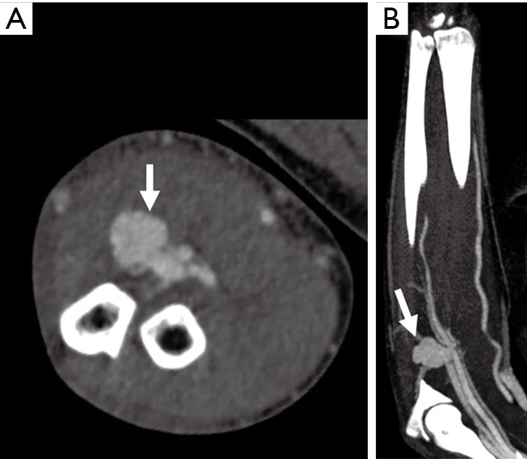
A 38-year-old man with penetrating glass injury from a motor vehicle accident 1 month ago. Axial (A) and coronal (B) CTA images showing a contrast outpouching along the proximal ulnar artery (white arrow) with extensive proximal venous enhancement along the ulnar side suggesting arteriovenous fistula. The venous enhancement starts at the pseudoaneurysm and extends proximally. CTA, CT angiography.
Figure 12.
Color Doppler US images in a patient with pulsatile distal left arm mass after trauma showing classic “Yin Yang” blood flow diagnostic of a pseudoaneurysm.
AVF can also occur after penetrating injuries. Imaging and diagnosis of AVF can be challenging. Early opacification of veins suggests AVF formation (Figure 11), however, can also be due to reactive hyperemia. Attention should be directed to the site of venous enhancement, as in AVF, venous enhancement is seen firstly at the site of injury whereas in reactive hyperemia it starts at the most distal aspect of the limb (Figure 11).
Frostbite
Frostbite is an effect of irreversible direct injury caused by ice crystallization resulting in freezing of tissues resulting in direct cellular damage and damage from ischemic necrosis. Frostbite occurs in hands and feet in majority (>90%) of cases. Imaging plays important role in delineating the extent of injury, direct surgical versus non-surgical treatment, and monitor response to treatment (29). Doppler may demonstrate slowing of blood flow in real-time (30). Although both CTA and MRA may show arterial occlusions, MRA is superior to CTA as it allows in addition to visualization of occluded vessels the imaging of surrounding tissues with clear line of demarcation between healthy and ischemic tissues. This additional feature may allow a window of opportunity for early intervention as angiography directed thrombolysis is the treatment of choice for salvageable tissue (31). Direct DSA should be preferred in patients with deep frostbite and symptoms of vascular compromise and presenting within 24 hours as it allows initiation of thrombolysis in the same setting (29).
Chronic trauma
Chronic trauma to the upper extremity vasculature is from repetitive blunt injury to the vessels. These injuries occur at typical sites like thoracic outlet (thoracic outlet syndrome), axilla (crutch injury), humeral neck (circumflex humeri artery injury in baseball pitchers), at the hook of hamate (hypothenar hamate syndrome). These can lead to vasospasm, stenosis, thrombosis, aneurysm or pseudoaneurysm formation or distal emboli. Few of these entities are described in detail.
TOS
TOS is a clinical condition characterized by the compression of the neurovascular bundle which transverses through the thoracic outlet between the anterior and middle scalene muscle bundles. The neurovascular bundle comprises of the brachial plexus, subclavian artery, and subclavian vein. Majority of patients present with predominantly neurological symptoms (accounting for around 90% cases) whereas arterial compression presenting with pain, pallor, coldness and paresthesia and venous compression symptoms presenting with pain and edema are less common. There is a wide spectrum of conditions which can predispose to TOS like a cervical rib, pseudarthrosis, fibrous bands, hypertrophy of scalene muscles or thoracic outlet mass (32,33).
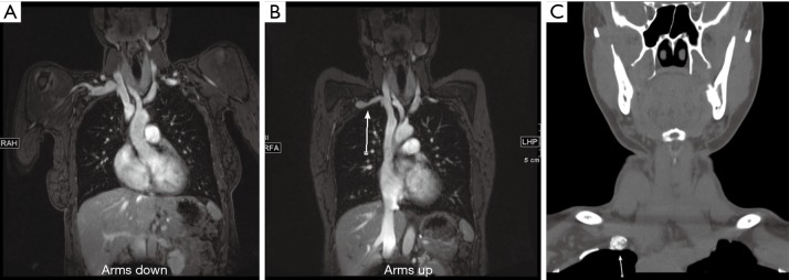
Both CTA and MRA are preferred imaging modality compared to Doppler or DSA, however, there has been an increase in the trend towards MRA, in patients without any contraindications to MRI because of its ability for better soft tissue characterization without radiation and better evaluation of venous and neurological compression. A contrast-enhanced 3D MRA utilizing neutral and hyperabduction arm positioning allows good imaging of the arteries and veins of bilateral upper extremities and thus provides an excellent non-invasive imaging alternative to DSA in patients with suspected vascular TOS (Figure 13). Contrast-enhanced 3D MRA is also an ideal and preferred imaging modality to identify restenosis or residual vascular compression in postoperative follow-up cases (34).
Figure 13.
A 34-year-old woman with right upper arm pain. MR angiography arms down (A) and arms up (B) images showing greater than 50% narrowing of the subclavian vein (arrow in B). Non-contrast CT neck image (C) showed pseudarthrosis at the first rib (arrow in C) from remote trauma. The symptoms resolved following this rib resection.
The first step of the imaging exam is to exclude any anatomical or pathological causes of TOS. The next step of the imaging test is to identify (and grade) any compression in neutral and hyperabduction position. Diameter change of greater than 30% for the subclavian artery and greater than 50% for subclavian vein is considered as a diagnostic criterion for TOS (35). An important factor to consider is to inject from the opposite side of the affected extremity to prevent contrast artifacts in the vein. It is paramount to correlate with the clinical findings as isolated asymptomatic compression of the subclavian vein can be seen in up to 52% and arterial compression of 11% of the population (36).
Hypothenar hammer syndrome
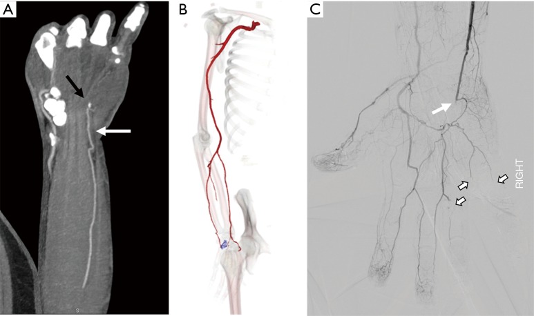
Hypothenar hammer syndrome is a form of vascular overuse condition caused by the repeated compression of the ulnar artery by the hypothenar eminence. This condition is described in people who get repeated blunt force on the hypothenar eminence from the occupational work (as a hammer to strike the objects) or recreation sports like volleyball, handball or badminton (37,38). This results in the compression of the superficial segment of the ulnar artery against the hook of the hamate as it exists the Guyon’s canal (Figure 14). This results in the injury to the intima resulting in the vasospasm, platelet aggression with thrombosis further leading to claudication and ischemia symptoms and can result in an aneurysm and pseudoaneurysm formations (39).
Figure 14.
A 48-year-old construction worker with cold 4th and 5th digit. Coronal and Volume-rendered CTA images showing occlusion of the ulnar artery at the level of the hook of the hamate (black arrow in A, blue color in B). Conventional angiography image (C) confirm occlusion of the distal ulnar artery (white arrow) just distal to the deep palmar arch branch with embolic occlusion of the digital branches to the 4th and 5th digit. CTA, CT angiography.
Although angiography is the gold standard test, with advances in imaging technology, CTA and MRA can be effective in diagnosing the condition. In addition to diagnosis, they can help in defining the nature of the arterial injury, patency of distal digital arteries and collateral circulation for pre-surgical evaluation (38). The treatment of this entity depends upon the nature and extent of the injury. The mild affection can be treated conservatively by avoiding trauma, using padded gloves or with medications like antiplatelet drugs or calcium channel blockers. Severe conditions with an aneurysm or a pseudoaneurysm are treated with surgical ligations and interposition grafts (37).
Crutch injury
Crutch induced arterial injury of the upper extremity is a relatively rare injury compared to the lower extremity injuries. The main pathophysiology behind this form of injury is the improper posture and placement of the body weight on the axillary pad of the crutch, causing a seven-fold increase in the force on the axilla, which further results in repeated trauma to the axillary and brachial artery. As sequelae of this trauma can result in the arterial stenosis, distal embolization and rarely aneurysmal formation (26,40,41). This distal embolization further can significantly affect the surgical outcomes in cases with arterial reconstructions and also increases the risk of amputation in 60% of the patients (40,42).
Hemodialysis access
Hemodialysis AVF is a surgically created communication between a superficial vein and an artery in the upper limb usually in the forearm for hemodialysis vascular access. Complications frequently occur, the common one of those include stenosis and occlusion and rarely pseudoaneurysms. Detection of these complications is crucial for prevention of fistula failure. Vascular ultrasound and Color Doppler is a popular method in evaluation of AVF because of impaired renal function. If the patient is hemodialysis dependent, iodinated contrast may be given as it cannot deteriorate the renal function any further. Arterial waveforms in the inflow artery and in the fistula are low resistance monophasic throughout, with peak systolic velocities ranging from 100–400 cm/sec and end diastolic velocities ranging from 60–200 cm/sec. The draining vein typical has peak systolic velocities between 30–100 cm/sec with arterial waveforms (43).
CTA can be used for evaluation of steal syndrome associated with dialysis fistula. Symptoms usually include a cool and painful extremity distal to the AVF related to ischemic symptoms from stealing of blood by the AVF. This occurs due to lack or decreased flow through the collaterals or increased flow through the AVF (43,44). CTA can help to identify central venous stenosis, arterial or venous anastomotic stenosis or pseudoaneurysm.
MRA can be used to evaluate AVF non-invasively assess hemodynamic stenosis, using time-resolved technique. MRA can image with larger FOV and with the use of time-resolved MRA, dynamic arterial and venous filling can be assessed. Time-resolved MRA is performed in coronal or oblique coronal planes to include the upper extremity AVF and chest concurrently. As these patients are dialysis dependent, therefore GBCA are not used for MRA though many studies have evaluated the role of contrast-enhanced MRA for evaluation of dialysis fistula (45-47). However, ferumoxytol can be safely given in patients with renal dysfunction as it is cleared by the reticuloendothelial system. In a study by Sigovan et al. (48), the ferumoxytol-enhanced MRA has shown superior image quality compared with non-enhanced TOF MRA. In a meta-analysis, Li et al. (49) showed that CTA and MRA have similar accuracy for evaluation of stenosis of autologous dialysis AVF. They recommended that both techniques can be used as an alternative or complement each other as well as DSA.
Vascular masses
Vascular masses in the upper extremity include an aneurysm, pseudoaneurysm, arterial-venous (AV) fistulas, vascular malformations and vascular tumors. The important role of the imaging modality is to describe the lesion, delineate the anatomy and image the inflow and outflow vascular territory, which would facilitate the roadmap for treatment options (4).
The most common vascular masses are the aneurysms and pseudoaneurysms (Figures 10-12) involving the arterial system. Venous aneurysms, however, are rare compared to the arterial aneurysms. Many are identified on routine imaging ordered for other indications, whereas venous aneurysms of the deep veins of the extremities are often manifested with venous thromboembolism (50). A true aneurysm, unlike pseudoaneurysm, involves all three vascular layers-intima, media, and adventitia. The most common etiology for pseudoaneurysm formation is the trauma followed by infection. Doppler still remains the first imaging modality of choice, which helps to determine both the content and the flow within the aneurysmal sac.
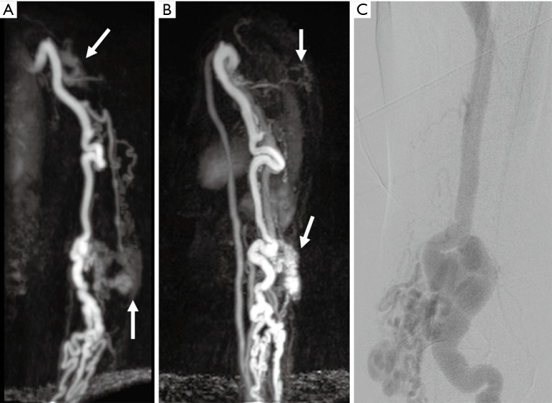
Vascular malformations and tumors include a wide spectrum of lesions which can represent a diagnostic challenge. Magnetic resonance (MR) imaging is still considered the most valuable modality for classification of vascular anomalies compared to CTA, ultrasound or DSA because it accurately demonstrates the extension of the lesion, involvement of adjacent structures, better evaluation of venous and neurological compression and its ability for better soft tissue characterization without radiation (Figure 15). Functional analysis by dynamic time-resolved contrast material-enhanced MRA provides information about the hemodynamic of vascular anomalies and with added differentiation of high-flow and low-flow vascular malformations. MR imaging offers an excellent imaging modality for post-treatment success, assessment of treatment success, and long-term follow-up (51).
Figure 15.
A 54-year-old woman with chronically enlarged arm veins with symptoms of hand ischemia. Time-resolved MR angiography coronal (A) and sagittal (B) images showing enlarged upper extremity arteries, tuft of abnormal vessels in the upper arm and near elbow (white arrows) and early enhancing enlarged veins consistent with arteriovenous malformations. Conventional angiography (C) performed for treatment also showing nidus around the elbow with enlarged draining arteries.
Vasculitis
Takayasu arteritis (TA)
TA is the most common granulomatous inflammation of large arteries. It has an early acute phase characterized by nonspecific constitutional symptoms such as hypertension, fever, and arthralgia. This is followed by a chronic occlusive phase which may be associated with angina, claudication, visual impairment and syncope depending on the organ system involved (52). The disease commonly involves the aorta and its major branches, causing arterial wall inflammation, followed by fibrosis and consequent stenosis. Less commonly, aneurysm formation may occur with associated mural thrombosis (53,54). Arterial stenosis develops in more than half of TA patients, while the disease results in aneurysm formation in only 10% (53). The aneurysm rupture is rare, as wall scarring may have a limiting influence on wall stress of the aneurysm (55). The disease typically affects young women and is most prevalent in Asia and South America. The diagnostic criteria of TA proposed by Sharma et al. (56) includes upper extremity involvement at mid subclavian artery as major diagnostic criteria. High probability of TA was defined with two major or one major and two minor criteria or four minor criteria. Mid subclavian artery involvement is more specific for TA than other sites of involvement and is described as a major criterion. Other vascular territories like the pulmonary artery, left common carotid, distal brachiocephalic trunk, descending thoracic aortic or abdominal aortic, or coronary artery involvement can also be seen are described as minor criteria (56,57).
CTA is a good test to identify the involvement of the aorta and other large vessels. As compared to DSA, CTA helps to diagnose early as it can diagnose at the stage of wall thickening without luminal abnormality. CT typically shows arterial wall thickening with mural enhancement and low-attenuation ring on delayed images. On pre-contrast CT scanning, the mural thickening is generally of a higher attenuation compared with the lumen, while on the post-enhanced CTA images, it exhibits a double ring enhancement pattern, which is best seen in the venous phase. A hypo-enhancing inner ring and an intensely enhancing outside ring may be observed in which the inside ring represents the swollen intima, while the outside ring indicates the active inflammation in the medial and adventitia (58).
MRA has the advantage of lacking exposure to ionizing radiation and iodinated contrast with diagnostic accuracy comparable to CTA and DSA. Vessel wall abnormalities include vessel wall edema on T2-sequences and mural contrast enhancement on T1-sequences (58-60). Limitations of MRA include poor visualization of calcifications, accentuation of stenosis on maximum intensity projection (MIP) images, relatively poor visualization of small vessels and the high costs of the procedure (61). In the inactive state, the arterial wall may be normal caliber or slightly thickened with calcifications on unenhanced images with absent or mild mural enhancement (59,60). CTA and MRA can also provide the information associated with ischemia of the end organs, such as decreased perfusion in the brain and lungs, which may be helpful for patient prognosis and treatment decision (58). Both CTA and MRA are though excellent modalities for assessing the distribution of disease but their role in assessment for disease activity is limited (62). FDG-PET CT may be better for evaluation of disease activity in large vessel vasculitis (63).
Giant cell arteritis (GCA)
GCA is the most common vasculitis of the medium and large-sized arteries. It is predominantly seen in patients with Northern European ancestry (64). Histopathologic features of GCA include a granulomatous inflammation of the vessel wall with multinucleated giant cells. The disease typically involves the superficial temporal artery with its branches, and the occipital artery with segmental involvement is typical (65). Classic clinical signs of GCA include new onset of a new type of headache in patients older than 50 years presenting with tenderness of the temporal arteries or decreased pulsation in that region. Involvement of upper extremity vasculature is less common though subclavian, axillary (Figure 16) or brachial artery may be involved (66). The typical imaging signs include vascular thickening with mural and periadventitial contrast enhancement. In patients with GCA involving the upper extremity, the disease course is typically benign though the prognosis is relatively worse with bilateral or right-side involvement (66). The establishment of the diagnosis GCA may be challenging if the traditional diagnostic standard temporal arterial biopsy is negative or inconclusive. MR or CT imaging may help to precise site of disease and compensate for false-negative histopathologic results due to skip lesions.
Figure 16.
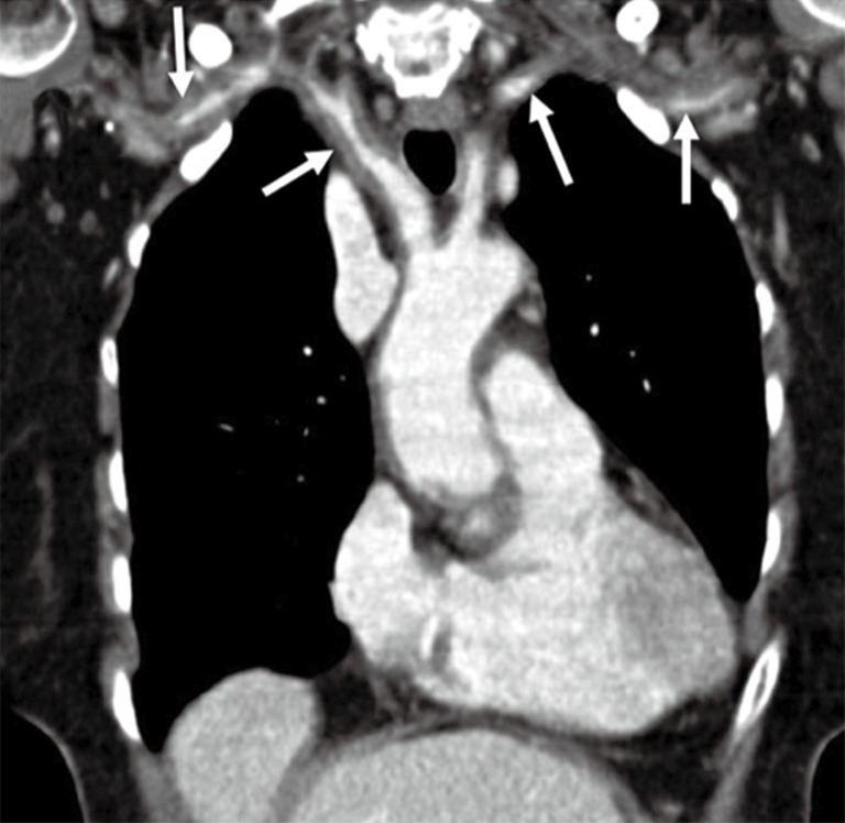
A 67-year-old woman with a history of headache, malaise, and fever. Coronal contrast-enhanced CT image shows diffuse circumferential thickening of aortic arch branches (arrows) in this patient with giant-cell arteritis on temporal artery biopsy. Reproduced with permission from (5).
Buerger’s disease
Buerger’s disease (also known as Thromboangiitis obliterans) is a non-atherosclerotic, segmental, inflammatory vasculitis, which affects small and medium-sized arteries, veins, and nerves of the extremities and characteristically spares visceral vessels (67). The disease process is histologically characterized by an inflammatory thrombus with minimal inflammation of the vessel wall. The disease predominantly affects males younger than 40–45 years with a history of current or past tobacco use (both smoking and chewing) and marijuana (5). The disease most commonly affects lower extremity but upper extremity involvement can be seen in approximately 45% cases (68). The disease predominantly affects vessels distal to the popliteal and brachial artery and the symptoms include intermittent claudication, superficial thrombophlebitis, paresthesia, rest pain, necrosis, ulceration or Raynaud phenomenon (67). The disease was classically diagnosed with DSA but the capabilities of MRA have significantly improved for diagnosis of small vessel vasculitis with increased spatial resolution. Imaging shows multiple areas of occlusions or stenosis and classic ‘corkscrew’ collaterals bypassing the areas of occlusion (68). Corkscrew collaterals are however not characteristic and can be seen in other diseases like scleroderma, CREST (calcinosis, Raynaud’s syndrome, esophageal dysmotility, sclerodactyly, and telangiectasia) syndrome, and in patients with amphetamine, cocaine or cannabis ingestion (69). Collectively, a classic history of tobacco use, the involvement of distal vasculature, concomitant or preceding lower extremity involvement, absence of any inflow disease, and findings of small vessel occlusion with corkscrew collaterals helps in making the diagnosis.
Systemic sclerosis (SSc)
SSc is an autoimmune disorder associated with alterations of the microvasculature, disturbances of the immune system, and deposition of collagen and other matrix substances in connective tissue. The general outcome depends on the extent and severity of vascular lesions (70). Raynaud’s phenomenon is often the prodromal feature of the disease, indicating that the vasculopathy may even be the central injury leading to organ damage (71-73). Vascular inflammation occurs at an early stage of SSc. The inability to resolve inflammation and repair microvascular damage promotes inflammatory cell recruitment, which in turn leads to persistent connective tissue remodeling and proliferation of the intima, leading to adventitial fibrosis (74).
Angiographic abnormalities in SSc hands primarily involve proper digital arteries and less frequently in the ulnar artery, the superficial arch, and the common digital arteries (Figure 17) (75,76). Angiography has been traditionally used to study the vessels of the hand due to the high spatial resolution. However, there is a risk of vasospasm with catheter angiography which can exacerbate the ischemic symptoms in these patients (77). Recently MRA has been used to study the vessels of the hand in patients with SSc. Allanore et al. (78) used contrast-enhanced MRA with 4 successive coronal 3-D gradient-echo sequences of 52 seconds each, acquired 30 seconds after gadolinium injection. This protocol allowed analysis of both the arterial and venous structures (78). They found a majority of patients had ≥4 damaged digital arteries and nearly all patients had abnormal venous return with lack of visible venous return in 42% (16/35) patients. Other imaging signs include a decreased number of dorsal veins and decreased luminal diameter of proper palmar digital artery (79). Sheehan et al. (16) used flow sensitive dephasing (FSD) MRA technique and showed improved image quality for all arterial segments when compared to time-resolved MRA and high-spatial-resolution MRA in patients with SSc.
Figure 17.
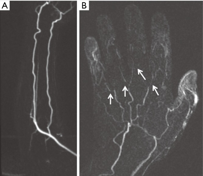
A 50-year-old woman with no previous history of any connective tissue disorder and symptoms consistent with “Raynaud phenomenon”. Subtracted coronal time-resolved MRA MIP images of the forearm (A) and hand (B) show normal forearm arteries with non-visualization of the superficial palmar arch, small caliber metacarpal arteries with multifocal narrowing, and non-visualization of the digital branches (arrows) consistent with “Raynaud Disease”. MIP, maximum intensity projection. Reproduced with permission from (5).
Thromboembolic disease
Thromboembolic disease of the upper extremity is less frequent than its incidence in the lower extremity. Almost all upper extremity emboli are cardiogenic with atrial fibrillation as the predisposing factor (80). Risk factors for cardiovascular diseases the eventually predispose to thromboembolism include hyperlipidemia, smoking, diabetes, hypertension, history of cancer, and obesity. Thromboembolism may also result from chronic repetitive injuries like TOS, hypothenar hamate syndrome (Figure 14) or crutch related injuries (5). Endovascular procedures are another source for upper extremity thromboembolism (81). Acute onset of symptoms indicates embolic event while thrombosis usually presents with chronic symptom of claudication. Both CTA and MRA can effectively screen for thrombosis and embolism in the upper extremities (2). Due to a smaller caliber of the upper extremity vessels, most emboli are occlusive and are seen as abrupt cut off of contrast column in the vessel. Filling defects with a surrounding or eccentric rim of contrast is seen in nonocclusive emboli (Figure 18). Proximal dilatation along with enhancement of the vessel wall of the segment containing thrombosis can be seen. CTA is optimal for evaluation of smaller upper extremity vessels for example hand vesselsdue to its superior spatial resolution. Time-resolved MRA with high relaxivity contrast agents can demonstrate the small forearm and hand vessels as well as collaterals which otherwise form less frequently in upper extremities. Non-contrast MRA techniques may show blockage of the vessels but usually exaggerate the grade of stenosis and a nonocclusive narrowing or emboli may appear as occlusive. Due to its easy availability and familiarity in interpreting images, CTA is performed in most centers.
Figure 18.
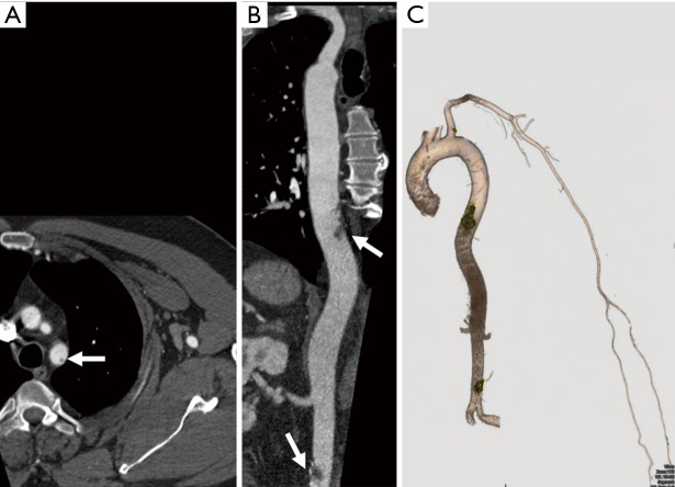
A 56-year-old man with pancreatic cancer and left-hand pain. CTA axial (A), reconstructed coronal (B), and volume-rendered (C) images showing non-occlusive thrombi at the subclavian origin, thoracic and the abdominal aorta (arrows in A and B, yellow in C) with patent inflow and outflow to the left wrist. CTA, CT angiography.
Subclavian steal
The terminology ‘subclavian steal’ refers to retrograde flow within the vertebral artery secondary to stenosis or occlusion of the segment of subclavian artery proximal to the origin of vertebral artery or from occlusion of brachiocephalic trunk (Figure 19). The segment of the subclavian artery distal to the stenosed segment is filled retrogradely from the vertebrobasilar circulation via the vertebral artery. Subclavian stenosis, which is more common on the left, usually presents with arm claudication. Patients can also present with vertigo and dizziness. If cerebral ischemic symptoms are present, the constellation of findings is generally referred to as subclavian steal syndrome. Most common etiology for subclavian stenosis is atherosclerosis. Other less frequent causes include arteritis, trauma, dissection, radiation strictures, vascular compression syndromes, fibromuscular dysplasia, neurofibromatosis type 1 (82).
Figure 19.
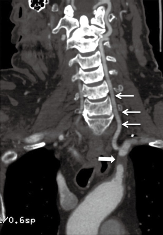
A 73-year-old woman with a history of vertigo and dizziness. Oblique coronal MPR image shows atherosclerotic disease of the left subclavian artery causing its short segment proximal occlusion (thick arrow) with reconstitution of the distal subclavian artery via the vertebral artery (thin arrows) consistent with subclavian steal syndrome. MPR, multiplanar reconstruction. Reproduced with permission from (5).
Although ultrasound is frequently used for assessing reversal of flow and extent of stenosis, CTA and MRA are vital to differentiate if the reversal of flow is secondary to a true subclavian steal or from proximal stenosis of the vertebral artery. The techniques also show additional extracranial and intracranial arterial stenosis. CTA and MRA have almost replaced DSA for diagnosis of the disease. CTA evaluates for the degree of stenosis, atherosclerotic plaque burden, wall calcification and intramural thrombus. MRA is better for evaluation of wall thickening seen in arteritis, for evaluating vascular compression syndromes and assessment of scarring seen with radiation. Time-resolved contrast-enhanced MRA techniques can demonstrate vertebral flow reversal and subclavian stenosis. For unilateral symptoms, contrast agent is done in the contralateral arm to avoid artifacts due to high concentrations of gadolinium contrast agent in adjacent vein. In patients with low GFR that precludes administration of IV contrast, non-contrast sequences such as two-dimensional TOF MRA and PC MRA can be used. In 2D TOF, a saturation band above the section demonstrates expected cephalad flow in the vertebral artery. Reversal of flow in vertebral arteries is confirmed when the artery is visualized when the saturation band is placed below the section of imaging. TOF MRA may overestimate the degree of stenosis in regions of complex flow or in vessels flowing parallel to the section plane called ‘in-plane saturation effect’ (81). Phase-contrast MRA technique measures vertebral artery flow direction and velocity.
The treatment options for improving arterial perfusion of the upper extremity and restoration of antegrade vertebral artery flow are percutaneous transluminal angioplasty or surgical revascularization procedures such as common carotid-to-subclavian artery bypass or transposition of the subclavian to the common carotid artery.
Radiation arteritis
Radiation-induced damage to carotid arteries has been extensively described (83,84). Subclavian and axillary arteries are subject to radiation damage during axillary external beam radiotherapy following breast cancer. However, arterial injury in the limbs after mastectomy may be overlooked because symptoms mimic postoperative lymphedema and nerve disorders. In vitro studies suggest that radiation induces endothelial activation which is prone to atherosclerosis as well as has prothrombotic properties. Radiation also causes endothelial dysfunction and nitric oxide-mediated, endothelial-dependent relaxation is impaired in human cervical arteries 4 to 6 weeks after irradiation (85). The pattern of radiation-induced arterial injury correlates with the time period elapsed since irradiation (86). Patients are usually not symptomatic the first few years after irradiation [5–10] years but may demonstrate mural non-occlusive thrombus on CTA and MRA. Wall fibrosis forms in the so-called ‘intermediate’ phase—10–20 years after exposure to radiation with arterial stenosis causes by fibrosis later on. MRA with black-blood vessel wall imaging may be superior to visualize circumferential fibrosis of the vessels which enhance on contrast administration. Additionally, radiation damage can cause accelerated atherosclerosis in the vessels within the radiation field which may present late-approximately 20–25 years after exposure. The difference in disease extent in these vessels, when compared with non-affected vessels in the same patient and even in the same limb, is the key (87).
Conclusions
Upper extremity vascular abnormalities are less common than those affecting the lower extremity vasculature but mostly need multi-modality evaluation. Color Doppler is widely available, can be performed at bedside, but is limited by inter-operator variability and inability to assess central vasculature. CTA is the most commonly performed imaging test and understanding of technical and patient factors is important for diagnostic image quality, appropriate protocol, and parameter selection. Contrast enhancement is the most important factor for CTA imaging. Modifications in image acquisition trigger (bolus tracking vs. test bolus), amount and rate of contrast injection, and considering patient factors like BMI and ejection fraction are helpful solutions to current limitations.
Continued advancement of CTA and MRA with 3D reconstructions and time-resolved MRA has resulted in significant increase in consideration of these imaging modalities for assessment of vascular pathologies which traditionally required conventional angiograms. High-quality CTA or MRA of upper extremity can be obtained using optimum imaging techniques and reducing artifacts. There is still an opportunity to develop these techniques further by developing technical principles to overcome image related artifacts to obtain optimized high-quality study. CTA is now available as a 24-hour imaging modality in the majority of the hospitals with MRA soon catching up for non-urgent and semi-urgent cases.
Acknowledgments
None.
Footnotes
Conflicts of Interest: The authors have no conflicts of interest to declare.
References
- 1.Dave RB, Fleischmann D. Computed Tomography Angiography of the Upper Extremities. Radiol Clin North Am 2016;54:101-14. 10.1016/j.rcl.2015.08.008 [DOI] [PubMed] [Google Scholar]
- 2.Bozlar U, Ogur T, Norton PT, et al. CT angiography of the upper extremity arterial system: Part 1-Anatomy, technique, and use in trauma patients. AJR Am J Roentgenol 2013;201:745-52. 10.2214/AJR.13.11207 [DOI] [PubMed] [Google Scholar]
- 3.Bannas P, Francois CJ, Reeder SB. Magnetic Resonance Angiography of the Upper Extremity. Magn Reson Imaging Clin N Am 2015;23:479-93. 10.1016/j.mric.2015.04.004 [DOI] [PubMed] [Google Scholar]
- 4.Hellinger JC, Epelman M, Rubin GD. Upper extremity computed tomographic angiography: state of the art technique and applications in 2010. Radiol Clin North Am 2010;48:397-421, ix. 10.1016/j.rcl.2010.02.022 [DOI] [PubMed] [Google Scholar]
- 5.Nagpal P, Maller V, Garg G, et al. Upper Extremity Runoff: Pearls and Pitfalls in Computed Tomography Angiography and Magnetic Resonance Angiography. Curr Probl Diagn Radiol 2017;46:115-29. 10.1067/j.cpradiol.2016.01.002 [DOI] [PubMed] [Google Scholar]
- 6.Nagpal P, Khandelwal A, Saboo SS, Bathla G, Steigner ML, Rybicki FJ. Modern imaging techniques: applications in the management of acute aortic pathologies. Postgrad Med J 2015;91:449-62. 10.1136/postgradmedj-2014-133178 [DOI] [PubMed] [Google Scholar]
- 7.Zimmerman NB. Occlusive vascular disorders of the upper extremity. Hand Clin 1993;9:139-50. [PubMed] [Google Scholar]
- 8.Shenoy S. Surgical anatomy of upper arm: what is needed for AVF planning. J Vasc Access 2009;10:223-32. [DOI] [PubMed]
- 9.Kaplanoglu H, Beton O. Evaluation of anatomy and variations of superficial palmar arch and upper extremity arteries with CT angiography. Surg Radiol Anat 2017;39:419-26. 10.1007/s00276-016-1750-6 [DOI] [PubMed] [Google Scholar]
- 10.Jens S, Kerstens MK, Legemate DA, et al. Diagnostic performance of computed tomography angiography in peripheral arterial injury due to trauma: a systematic review and meta-analysis. Eur J Vasc Endovasc Surg 2013;46:329-37. 10.1016/j.ejvs.2013.04.034 [DOI] [PubMed] [Google Scholar]
- 11.ACR Manual on Contrast Media. The American College of Radiology 2017. Accessed May 1, 2018. Available online: https://www.acr.org/-/media/ACR/Files/Clinical-Resources/Contrast_Media.pdf
- 12.Almutairi A, Sun Z, Poovathumkadavi A, et al. Dual Energy CT Angiography of Peripheral Arterial Disease: Feasibility of Using Lower Contrast Medium Volume. PLoS One 2015;10:e0139275. 10.1371/journal.pone.0139275 [DOI] [PMC free article] [PubMed] [Google Scholar]
- 13.Miyazaki M, Akahane M. Non-contrast enhanced MR angiography: established techniques. JMRI 2012;35:1-19. 10.1002/jmri.22789 [DOI] [PubMed] [Google Scholar]
- 14.Wheaton AJ, Miyazaki M. Non-contrast enhanced MR angiography: physical principles. JMRI 2012;36:286-304. 10.1002/jmri.23641 [DOI] [PubMed] [Google Scholar]
- 15.Amin P, Collins JD, Koktzoglou I, et al. Evaluating peripheral arterial disease with unenhanced quiescent-interval single-shot MR angiography at 3 T. AJR Am J Roentgenol 2014;202:886-93. 10.2214/AJR.13.11243 [DOI] [PubMed] [Google Scholar]
- 16.Sheehan JJ, Fan Z, Davarpanah AH, et al. Nonenhanced MR angiography of the hand with flow-sensitive dephasing-prepared balanced SSFP sequence: initial experience with systemic sclerosis. Radiology 2011;259:248-56. 10.1148/radiol.10100851 [DOI] [PMC free article] [PubMed] [Google Scholar]
- 17.Oh LC, Lau KK, Devapalasundaram A, et al. Efficacy of 'fine' focal spot imaging in CT abdominal angiography. European radiology 2014;24:3010-6. 10.1007/s00330-014-3368-6 [DOI] [PubMed] [Google Scholar]
- 18.Wong VW, Katz RD, Higgins JP. Interpretation of upper extremity arteriography: vascular anatomy and pathology [corrected]. Hand Clin 2015;31:121-34. 10.1016/j.hcl.2014.09.009 [DOI] [PubMed] [Google Scholar]
- 19.Katayama H, Yamaguchi K, Kozuka T, et al. Adverse reactions to ionic and nonionic contrast media. A report from the Japanese Committee on the Safety of Contrast Media. Radiology 1990;175:621-8. 10.1148/radiology.175.3.2343107 [DOI] [PubMed] [Google Scholar]
- 20.Shehadi WH. Adverse reactions to intravascularly administered contrast media. A comprehensive study based on a prospective survey. Am J Roentgenol Radium Ther Nucl Med 1975;124:145-52. 10.2214/ajr.124.1.145 [DOI] [PubMed] [Google Scholar]
- 21.Expert Panel on MR Safety , Kanal E, Barkovich AJ, et al. ACR guidance document on MR safe practices: 2013. JMRI 2013;37:501-30. 10.1002/jmri.24011 [DOI] [PubMed] [Google Scholar]
- 22.Wolf GL, Mishkin MM, Roux SG, et al. Comparison of the rates of adverse drug reactions. Ionic contrast agents, ionic agents combined with steroids, and nonionic agents. Invest Radiol 1991;26:404-10. 10.1097/00004424-199105000-00003 [DOI] [PubMed] [Google Scholar]
- 23.Davenport MS, Cohan RH, Caoili EM, et al. Repeat contrast medium reactions in premedicated patients: frequency and severity. Radiology 2009;253:372-9. 10.1148/radiol.2532090465 [DOI] [PubMed] [Google Scholar]
- 24.Hilbert S, Jahnke C, Loebe S, et al. Cardiovascular magnetic resonance imaging in patients with cardiac implantable electronic devices: a device-dependent imaging strategy for improved image quality. Eur Heart J Cardiovasc Imaging 2018;19:1051-61. 10.1093/ehjci/jex243 [DOI] [PubMed] [Google Scholar]
- 25.Menzoian JO, Doyle JE, Cantelmo NL, et al. A comprehensive approach to extremity vascular trauma. Arch Surg 1985;120:801-5. 10.1001/archsurg.1985.01390310039008 [DOI] [PubMed] [Google Scholar]
- 26.Miller-Thomas MM, West OC, Cohen AM. Diagnosing traumatic arterial injury in the extremities with CT angiography: pearls and pitfalls. Radiographics 2005;25 Suppl 1:S133-42. 10.1148/rg.25si055511 [DOI] [PubMed] [Google Scholar]
- 27.Nagpal P, Saboo SS, Khandelwal A, et al. Traumatic right atrial pseudoaneurysm. Cardiovasc Diagn Ther 2015;5:141-4. [DOI] [PMC free article] [PubMed] [Google Scholar]
- 28.Foster BR, Anderson SW, Soto JA. CT angiography of extremity trauma. Tech Vasc Interv Radiol 2006;9:156-66. 10.1053/j.tvir.2007.02.009 [DOI] [PubMed] [Google Scholar]
- 29.Millet JD, Brown RK, Levi B, et al. Frostbite: Spectrum of Imaging Findings and Guidelines for Management. Radiographics 2016;36:2154-69. 10.1148/rg.2016160045 [DOI] [PMC free article] [PubMed] [Google Scholar]
- 30.Hutchison RL. Frostbite of the hand. J Hand Surg Am 2014;39:1863-8. 10.1016/j.jhsa.2014.01.035 [DOI] [PubMed] [Google Scholar]
- 31.Barker JR, Haws MJ, Brown RE, et al. Magnetic resonance imaging of severe frostbite injuries. Ann Plast Surg 1997;38:275-9. 10.1097/00000637-199703000-00015 [DOI] [PubMed] [Google Scholar]
- 32.Sanders RJ, Hammond SL, Rao NM. Thoracic outlet syndrome: a review. Neurologist 2008;14:365-73. 10.1097/NRL.0b013e318176b98d [DOI] [PubMed] [Google Scholar]
- 33.Watson HI, Hopper GP, Kovacs P. Congenital pseudarthrosis of the clavicle causing thoracic outlet syndrome. BMJ Case Rep 2013;2013. [DOI] [PMC free article] [PubMed]
- 34.Ersoy H, Steigner ML, Coyner KB, et al. Vascular thoracic outlet syndrome: protocol design and diagnostic value of contrast-enhanced 3D MR angiography and equilibrium phase imaging on 1.5- and 3-T MRI scanners. AJR Am J Roentgenol 2012;198:1180-7. 10.2214/AJR.11.6417 [DOI] [PubMed] [Google Scholar]
- 35.Moriarty JM, Bandyk DF, Broderick DF, et al. ACR Appropriateness Criteria Imaging in the Diagnosis of Thoracic Outlet Syndrome. J Am Coll Radiol 2015;12:438-43. 10.1016/j.jacr.2015.01.016 [DOI] [PubMed] [Google Scholar]
- 36.Demondion X, Bacqueville E, Paul C, et al. Thoracic outlet: assessment with MR imaging in asymptomatic and symptomatic populations. Radiology 2003;227:461-8. 10.1148/radiol.2272012111 [DOI] [PubMed] [Google Scholar]
- 37.Ablett CT, Hackett LA. Hypothenar hammer syndrome: case reports and brief review. Clin Med Res 2008;6:3-8. 10.3121/cmr.2008.775 [DOI] [PMC free article] [PubMed] [Google Scholar]
- 38.Schröttle A, Czihal M, Lottspeich C, et al. Hypothenar hammer syndrome. Vasa 2015;44:179-85. 10.1024/0301-1526/a000427 [DOI] [PubMed] [Google Scholar]
- 39.Carter PM, Hollinshead PA, Desmond JS. Hypothenar hammer syndrome: case report and review. J Emerg Med 2013;45:22-5. 10.1016/j.jemermed.2012.11.100 [DOI] [PubMed] [Google Scholar]
- 40.Moon IS, Hwang JK, Kim JI. Recurrent upper extremity embolism due to a crutch-induced arterial injury: a different cause of upper extremity embolism. Ann Vasc Surg 2010;24:554.e7-554.e12. 10.1016/j.avsg.2009.11.005 [DOI] [PubMed] [Google Scholar]
- 41.Ang EJ, Goh JC, Bose K, et al. Biofeedback device for patients on axillary crutches. Arch Phys Med Rehabil 1989;70:644-7. [PubMed] [Google Scholar]
- 42.McFall B, Arya N, Soong C, et al. Crutch induced axillary artery injury. Ulster Med J 2004;73:50-2. [PMC free article] [PubMed] [Google Scholar]
- 43.Finlay DE, Longley DG, Foshager MC, et al. Duplex and color Doppler sonography of hemodialysis arteriovenous fistulas and grafts. Radiographics 1993;13:983-9. 10.1148/radiographics.13.5.8210602 [DOI] [PubMed] [Google Scholar]
- 44.Scheible W, Skram C, Leopold GR. High resolution real-time sonography of hemodialysis vascular access complications. AJR Am J Roentgenol 1980;134:1173-6. 10.2214/ajr.134.6.1173 [DOI] [PubMed] [Google Scholar]
- 45.Froger CL, Duijm LE, Liem YS, et al. Stenosis detection with MR angiography and digital subtraction angiography in dysfunctional hemodialysis access fistulas and grafts. Radiology 2005;234:284-91. 10.1148/radiol.2341031859 [DOI] [PubMed] [Google Scholar]
- 46.Takahashi N, Sato M, Niitsu M, et al. Value of subtraction in fat-saturated three-dimensional contrast-enhanced magnetic resonance angiography of the hemodialysis fistula. Acta Radiol 2004;45:608-15. 10.1080/02841850410001141 [DOI] [PubMed] [Google Scholar]
- 47.Cavagna E, D'Andrea P, Schiavon F, et al. Failing hemodialysis arteriovenous fistula and percutaneous treatment: imaging with CT, MRI and digital subtraction angiography. Cardiovasc Intervent Radiol 2000;23:262-5. 10.1007/s002700010066 [DOI] [PubMed] [Google Scholar]
- 48.Sigovan M, Gasper W, Alley HF, et al. USPIO-enhanced MR angiography of arteriovenous fistulas in patients with renal failure. Radiology 2012;265:584-90. 10.1148/radiol.12112694 [DOI] [PMC free article] [PubMed] [Google Scholar]
- 49.Li B, Li Q, Chen C, et al. Diagnostic accuracy of computer tomography angiography and magnetic resonance angiography in the stenosis detection of autologuous hemodialysis access: a meta-analysis. PLoS One 2013;8:e78409. 10.1371/journal.pone.0078409 [DOI] [PMC free article] [PubMed] [Google Scholar]
- 50.Teter KA, Maldonado TM, Adelman MA. A systematic review of venous aneurysms by anatomic location. J Vasc Surg Venous Lymphat Disord 2018;6:408-13. 10.1016/j.jvsv.2017.11.014 [DOI] [PubMed] [Google Scholar]
- 51.Flors L, Leiva-Salinas C, Maged IM, et al. MR imaging of soft-tissue vascular malformations: diagnosis, classification, and therapy follow-up. Radiographics: a review publication of the Radiological Society of North America, Inc 2011;31:1321-40; discussion 1340-1. [DOI] [PubMed]
- 52.Kerr G. Takayasu's arteritis. Curr Opin Rheumatol 1994;6:32-8. 10.1097/00002281-199401000-00006 [DOI] [PubMed] [Google Scholar]
- 53.Brunner J, Feldman BM, Tyrrell PN, et al. Takayasu arteritis in children and adolescents. Rheumatology (Oxford, England) 2010;49:1806-14. 10.1093/rheumatology/keq167 [DOI] [PubMed] [Google Scholar]
- 54.Ozen S, Pistorio A, Iusan SM, et al. EULAR/PRINTO/PRES criteria for Henoch-Schonlein purpura, childhood polyarteritis nodosa, childhood Wegener granulomatosis and childhood Takayasu arteritis: Ankara 2008. Part II: Final classification criteria. Ann Rheum Dis 2010;69:798-806. 10.1136/ard.2009.116657 [DOI] [PubMed] [Google Scholar]
- 55.Sueyoshi E, Sakamoto I, Hayashi K. Aortic aneurysms in patients with Takayasu's arteritis: CT evaluation. AJR Am J Roentgenol 2000;175:1727-33. 10.2214/ajr.175.6.1751727 [DOI] [PubMed] [Google Scholar]
- 56.Sharma BK, Jain S, Suri S, et al. Diagnostic criteria for Takayasu arteritis. International journal of cardiology 1996;54 Suppl:S141-7. 10.1016/S0167-5273(96)88783-3 [DOI] [PubMed] [Google Scholar]
- 57.Rodriguez F, Degnan KO, Nagpal P, et al. Insidious: Takayasu Arteritis. Am J Med 2015;128:1288-91. 10.1016/j.amjmed.2015.07.007 [DOI] [PubMed] [Google Scholar]
- 58.Zhu FP, Luo S, Wang ZJ, et al. Takayasu arteritis: imaging spectrum at multidetector CT angiography. Br J Radiol 2012;85:e1282-92. 10.1259/bjr/25536451 [DOI] [PMC free article] [PubMed] [Google Scholar]
- 59.Angeli E, Vanzulli A, Venturini M, et al. The role of radiology in the diagnosis and management of Takayasu's arteritis. J Nephrol 2001;14:514-24. [PubMed] [Google Scholar]
- 60.Chung JW, Kim HC, Choi YH, et al. Patterns of aortic involvement in Takayasu arteritis and its clinical implications: evaluation with spiral computed tomography angiography. J Vasc Surg 2007;45:906-14. 10.1016/j.jvs.2007.01.016 [DOI] [PubMed] [Google Scholar]
- 61.Gotway MB, Araoz PA, Macedo TA, et al. Imaging findings in Takayasu's arteritis. AJR Am J Roentgenol 2005;184:1945-50. 10.2214/ajr.184.6.01841945 [DOI] [PubMed] [Google Scholar]
- 62.Kato Y, Terashima M, Ohigashi H, et al. Vessel Wall Inflammation of Takayasu Arteritis Detected by Contrast-Enhanced Magnetic Resonance Imaging: Association with Disease Distribution and Activity. PLoS One 2015;10:e0145855. 10.1371/journal.pone.0145855 [DOI] [PMC free article] [PubMed] [Google Scholar]
- 63.Veeranna V, Fisher A, Nagpal P, et al. Utility of multimodality imaging in diagnosis and follow-up of aortitis. J Nucl Cardiol 2016;23:590-5. 10.1007/s12350-015-0219-z [DOI] [PubMed] [Google Scholar]
- 64.Nuenninghoff DM, Hunder GG, Christianson TJ, et al. Mortality of large-artery complication (aortic aneurysm, aortic dissection, and/or large-artery stenosis) in patients with giant cell arteritis: a population-based study over 50 years. Arthritis Rheum 2003;48:3532-7. 10.1002/art.11480 [DOI] [PubMed] [Google Scholar]
- 65.Klein RG, Campbell RJ, Hunder GG, et al. Skip lesions in temporal arteritis. Mayo Clinic proceedings 1976;51:504-10. [PubMed] [Google Scholar]
- 66.Czihal M, Piller A, Schroettle A, et al. Outcome of giant cell arteritis of the arm arteries managed with medical treatment alone: cross-sectional follow-up study. Rheumatology (Oxford, England) 2013;52:282-6. 10.1093/rheumatology/kes239 [DOI] [PubMed] [Google Scholar]
- 67.Olin JW. Thromboangiitis obliterans (Buerger's disease). N Engl J Med 2000;343:864-9. 10.1056/NEJM200009213431207 [DOI] [PubMed] [Google Scholar]
- 68.Małecki R, Zdrojowy K, Adamiec R. Thromboangiitis obliterans in the 21st century--a new face of disease. Atherosclerosis 2009;206:328-34. 10.1016/j.atherosclerosis.2009.01.042 [DOI] [PubMed] [Google Scholar]
- 69.Eichhorn J, Sima D, Lindschau C, et al. Antiendothelial cell antibodies in thromboangiitis obliterans. Am J Med Sci 1998;315:17-23. [DOI] [PubMed] [Google Scholar]
- 70.Steen VD, Medsger TA., Jr Severe organ involvement in systemic sclerosis with diffuse scleroderma. Arthritis Rheum 2000;43:2437-44. [DOI] [PubMed] [Google Scholar]
- 71.D'Angelo WA, Fries JF, Masi AT, et al. Pathologic observations in systemic sclerosis (scleroderma). A study of fifty-eight autopsy cases and fifty-eight matched controls. Am J Med 1969;46:428-40. 10.1016/0002-9343(69)90044-8 [DOI] [PubMed] [Google Scholar]
- 72.Campbell PM, LeRoy EC. Pathogenesis of systemic sclerosis: a vascular hypothesis. Semin Arthritis Rheum 1975;4:351-68. 10.1016/0049-0172(75)90017-7 [DOI] [PubMed] [Google Scholar]
- 73.Herrick AL. Vascular function in systemic sclerosis. Curr Opin Rheumatol 2000;12:527-33. 10.1097/00002281-200011000-00009 [DOI] [PubMed] [Google Scholar]
- 74.Kahaleh MB. Vascular involvement in systemic sclerosis (SSc). Clin Exp Rheumatol 2004;22:S19-23. [PubMed] [Google Scholar]
- 75.Janevski B. Arteries of the hand in patients with scleroderma. Diagnostic imaging in clinical medicine 1986;55:262-5. [PubMed] [Google Scholar]
- 76.Dabich L, Bookstein JJ, Zweifler A, et al. Digital arteries in patients with scleroderma. Arteriographic and plethysmographic study. Arch Intern Med 1972;130:708-14. 10.1001/archinte.1972.03650050036006 [DOI] [PubMed] [Google Scholar]
- 77.Lee VS, Lee HM, Rofsky NM. Magnetic resonance angiography of the hand. A review. Invest Radiol 1998;33:687-98. 10.1097/00004424-199809000-00025 [DOI] [PubMed] [Google Scholar]
- 78.Allanore Y, Seror R, Chevrot A, et al. Hand vascular involvement assessed by magnetic resonance angiography in systemic sclerosis. Arthritis Rheum 2007;56:2747-54. 10.1002/art.22734 [DOI] [PubMed] [Google Scholar]
- 79.Wang J, Yarnykh VL, Molitor JA, et al. Micro magnetic resonance angiography of the finger in systemic sclerosis. Rheumatology (Oxford, England) 2008;47:1239-43. 10.1093/rheumatology/ken215 [DOI] [PubMed] [Google Scholar]
- 80.Deguara J, Ali T, Modarai B, et al. Upper limb ischemia: 20 years experience from a single center. Vascular 2005;13:84-91. 10.1258/rsmvasc.13.2.84 [DOI] [PubMed] [Google Scholar]
- 81.Stepansky F, Hecht EM, Rivera R, et al. Dynamic MR angiography of upper extremity vascular disease: pictorial review. Radiographics 2008;28:e28. 10.1148/radiol.e28 [DOI] [PubMed] [Google Scholar]
- 82.Oderich GS, Sullivan TM, Bower TC, et al. Vascular abnormalities in patients with neurofibromatosis syndrome type I: clinical spectrum, management, and results. J Vasc Surg 2007;46:475-84. 10.1016/j.jvs.2007.03.055 [DOI] [PubMed] [Google Scholar]
- 83.Xu J, Cao Y. Radiation-induced carotid artery stenosis: a comprehensive review of the literature. Interv Neurol 2014;2:183-92. 10.1159/000363068 [DOI] [PMC free article] [PubMed] [Google Scholar]
- 84.Nagpal P, Ellika S, Jain R. Neuroimaging of Cerebrovascular Complications in Cancer Patients. Handbook of Neuro-Oncology Neuroimaging (Second Edition), 2016:797-810. [Google Scholar]
- 85.Borghini A, Gianicolo EA, Picano E, et al. Ionizing radiation and atherosclerosis: current knowledge and future challenges. Atherosclerosis 2013;230:40-7. 10.1016/j.atherosclerosis.2013.06.010 [DOI] [PubMed] [Google Scholar]
- 86.Mellière D, Becquemin JP, Berrahal D, et al. Management of radiation-induced occlusive arterial disease: a reassessment. J Cardiovasc Surg (Torino) 1997;38:261-9. [PubMed] [Google Scholar]
- 87.Nagpal P, Jain R. It’s Not Just the Tumor: CNS Paraneoplastic Syndromes and Cerebrovascular Complications of Cancers. Brain Tumor Imaging 2016:184-95. [Google Scholar]


