

Abstract
Purpose
Currently, four‐dimensional (4D) cone‐beam computed tomography (CBCT) requires a 3–4 min full‐fan scan to ensure usable image quality. Recent advancements in sparse‐view 4D‐CBCT reconstruction have opened the possibility to reduce scan time and dose. The aim of this study is to provide a common framework for systematically evaluating algorithms for 4D‐CBCT reconstruction from a 1‐min scan. Using this framework, the AAPM‐sponsored SPARE Challenge was conducted in 2018 to identify and compare state‐of‐the‐art algorithms.
Methods
A clinically realistic CBCT dataset was simulated using patient CT volumes from the 4D‐Lung database. The selected patients had multiple 4D‐CT sessions, where the first 4D‐CT was used as the prior CT, and the rest were used as the ground truth volumes for simulating CBCT projections. A GPU‐based Monte Carlo tool was used to simulate the primary, scatter, and quantum noise signals. A total of 32 CBCT scans of nine patients were generated. Additional qualitative analysis was performed on a clinical Varian and clinical Elekta dataset to validate the simulation study. Participants were blinded from the ground truth, and were given 3 months to apply their reconstruction algorithms to the projection data. The submitted reconstructions were analyzed in terms of root‐mean‐squared‐error (RMSE) and structural similarity index (SSIM) with the ground truth within four different region‐of‐interests (ROI) — patient body, lungs, planning target volume (PTV), and bony anatomy. Geometric accuracy was quantified as the alignment error of the PTV.
Results
Twenty teams participated in the challenge, with five teams completing the challenge. Techniques involved in the five methods included iterative optimization, motion‐compensation, and deformation of the prior 4D‐CT. All five methods rendered significant reduction in noise and streaking artifacts when compared to the conventional Feldkamp–Davis–Kress (FDK) algorithm. The RMS of the three‐dimensional (3D) target registration error of the five methods ranged from 1.79 to 3.00 mm. Qualitative observations from the Varian and Elekta datasets mostly concur with those from the simulation dataset. Each of the methods was found to have its own strengths and weaknesses. Overall, the MA‐ROOSTER method, which utilizes a 4D‐CT motion model for temporal regularization, had the best and most consistent image quality and accuracy.
Conclusion
The SPARE Challenge represents the first framework for systematically evaluating state‐of‐the‐art algorithms for 4D‐CBCT reconstruction from a 1‐min scan. Results suggest the potential for reducing scan time and dose for 4D‐CBCT. The challenge dataset and analysis framework are publicly available for benchmarking future reconstruction algorithms.
Keywords: 4D‐CBCT, grand challenge, image reconstruction
1. Introduction
Stereotactic ablative radiotherapy (SABR) is becoming an effective treatment paradigm in radiotherapy. Compared to traditional fractionated radiotherapy, SABR delivers higher radiation dose per fraction, which requires higher targeting accuracy. Onboard four‐dimensional (4D) volumetric verification of target location thus becomes critical for the treatment of tumors that experience substantial respiratory motion such as lung tumors and liver tumors. The emergence of 4D cone‐beam computed tomography (CBCT)1 has enabled onboard verification of target location and motion range while reducing motion artifacts. Compared to three‐dimensional (3D)‐CBCT, 4D‐CBCT has been shown to reduce setup errors2 and enable measurement of daily target motion.3
Conventionally, 4D‐CBCT images are computed by sorting the projections into different respiratory bins, and reconstructing separately using the Feldkamp–Davis–Kress (FDK) algorithm.4 This leads to longer acquisition time (3–4 min) and higher imaging dose compared to a standard CBCT scan, which takes one minute to acquire. Despite the longer acquisition time, breathing irregularities and long breathing cycles can still cause data sparsity and lead to streaking artifacts. In addition, to ensure sufficient image quality, 4D‐CBCT is usually acquired in the full‐fan mode, where the limited field of view (FOV) truncates half of the patient body. To obtain a larger FOV, half‐fan acquisition can be used, but the number of projections measuring each point of the FOV is approximately halved, causing more noise and artifacts. Techniques to enable high‐quality 4D‐CBCT from a 1‐min half‐fan scan will improve the practicality of 4D‐CBCT, potentially making onboard 4D volumetric verification routine practice for thoracic‐abdominal SABR.
Various reconstruction algorithms have been proposed to improve 4D‐CBCT image quality. A popular alternative to the FDK algorithm is the McKinnon‐Bates (MKB) algorithm,5, 6 which uses the motion blurred 3D‐CBCT as a prior to combat data sparsity. While the MKB algorithm is computationally efficient, the improvement in image quality is often limited, with the resultant images often suffering from both residual motion and streaking artifacts.7
More advanced techniques can be categorized into three types: iterative, motion‐compensated, and prior deforming. Iterative approaches employ regularization terms in an optimization framework to combat data sparsity. Compressed sensing‐based regularization techniques have shown good performance in 4D‐CBCT reconstruction, with examples including the total‐variation8 and the prior‐image‐constraint‐compressed‐sensing (PICCS) method.9 Other iterative approaches include the use of spatiotemporal tensor framelet,10 temporal nonlocal means.11 Hansen et al.12 had demonstrated clinically usable image quality from some of the iterative approaches when applied to a 1‐min half‐fan scan. Motion‐compensated approaches overcome data sparsity by deforming the reconstruction in each respiratory bin to one single bin, and then superimposing the deformed reconstructions to form a high quality image. The deformation vector field (DVF) can be estimated from the planning CT,13 a preliminary reconstruction,14, 15 or the projections.16, 17 Prior deforming approaches solve for a DVF that best deforms a high quality prior image, usually the planning CT, to match with the CBCT projection data.18, 19 There are also hybrid approaches that combine multiple techniques. Examples include the MCIR method,20 the SMEIR method,21 the MA‐ROOSTER method,22 and motion‐compensated total‐variation regularization.23 Apart from the abovementioned techniques, machine learning represents another category that has yet to be investigated for 4D‐CBCT reconstruction.
In addition to software advancement, several approaches to improve image quality and reduce imaging dose by adapting the acquisition (e.g., gantry rotation and imaging frame rate) to patient breathing have also been proposed.24, 25, 26, 27 As this paper is focused on the use of advanced reconstruction algorithms to improve 4D‐CBCT image quality from a standard 1‐min scan, approaches that alter the acquisition of the projections are outside the scope of this study.
A common limitation to the evaluation of reconstruction algorithms is the lack of ground truth. While phantom studies can overcome this limitation, phantoms do not exhibit the same level of complexity as human anatomy does. An algorithm may perform well on a phantom case, but fail to preserve fine details on a patient case. In addition, digital phantom studies often simulate CBCT projections by performing a Radon transform of the ground truth volume, which does not model the underlying physics properly, particularly photon scatter. Comparison studies that investigated patient cases7, 12 relied on qualitative evaluation of the images and image quality metrics such as the signal‐to‐noise ratio that may not directly represent the accuracy of the reconstruction.
The aim of the AAPM‐sponsored SPARE Challenge (SPArse‐view REconstruction Challenge for 4D‐CBCT; spare scan time and spare dose) is to systematically investigate the image quality produced by advanced reconstruction algorithms when applied to a 1‐min scan using clinically realistic data and with an objective ground truth. An additional aim is to provide a common dataset and evaluation framework for future 4D‐CBCT studies.
The rest of this paper is organized as follows. Section 2 describes the generation and processing of the datasets, the mechanism of the challenge study, and the metrics used for algorithm evaluation. Section 3 compares the reconstruction results from the participating algorithms both qualitatively and quantitatively. Section 4 discusses the implications of the results as well as limitations of the study.
2. Materials and methods
2.1. Simulated dataset
The ground truth volumes used to simulate CBCT projections were selected from patient CT volumes in the 4D‐Lung dataset28 from The Cancer Imaging Archive (TCIA). The 4D‐lung dataset consists of patients with locally advanced non‐small‐cell lung cancer (NSCLC) receiving 3D conformal radiotherapy. Most patients had 2–5 CT scans acquired over 4–6 weeks, allowing multiple CBCT sessions to be simulated for each patient. Additionally, the earliest CT scan was used as the pretreatment 4D‐CT scan in the SPARE Challenge, as many reconstruction algorithms require the pretreatment 4D‐CT as a prior. Twelve of the patients had at least two 4D‐CT scans with acceptable image quality, that is, <5 mm motion artifacts as visually inspected, and were used for the challenge study. A total of 32 1‐min half‐scan CBCT scans were simulated.
CBCT projections were generated using a graphics processing unit (GPU)‐based Monte Carlo simulation tool.29 The primary signal was computed using a trilinear ray‐tracing algorithm. A Monte Carlo simulation was performed to produce the scatter signal and the noise signal. The noise signal was scaled according to the simulated mAs level. Each simulated scan consisted of 680 projections spanning 360 gantry rotation. To simulate motion, for each scan, a 1‐min long real‐time position management (RPM) (Varian Medical Systems, Palo Alto, US) trace measured from the corresponding patient was converted into respiratory phase. For each projection, the simulated volume was determined by the respiratory phase assigned to that frame. The dimensions and pixel size of the simulated projections were 512 × 384 and 0.776 mm. The source‐to‐isocenter distance (SID) and source‐to‐detector distance (SDD) were 1000 and 1500 mm. The half‐fan displacement was 148 mm. A 120 kVp beam with a pulse length of 20 ms going through a half‐fan bowtie filter was simulated.
The 32 simulated scans were split into three simulation types:
Scatter‐free: projections consist of the primary and noise signals only. Tube current was 40 mA.
Normal: projections consist of the primary, scatter, and noise signals. Tube current was 40 mA.
Low dose: projections consist of the primary, scatter, and noise signals. Tube current was 20 mA.
Including scatter‐free cases allows the effects of scatter correction methods to be studied separately from that of the reconstruction algorithms. The low‐dose cases exploit the possibility of further dose reduction. In total, there were 12 normal scans, 10 scatter‐free scans, and 7 low‐dose scans.
2.2. Clinical datasets
A clinical Varian dataset and a clinical Elekta dataset were included to verify that the simulated dataset represents the clinical reality accurately. Although quantitative analysis was not available with the clinical datasets due to the lack of ground truth, qualitative comparison of the reconstructions between the simulated and clinical datasets would reveal any potential bias due to limitation in the simulation methodology. The clinical Varian dataset consisted of five patients with locally advanced NSCLC receiving 3D conformal radiotherapy and a total of thirty 8‐min half‐fan CBCT scans (six scans per patient) acquired on a Varian Trilogy (Varian Medical Systems, Palo Alto, USA).30 Each scan had 2400–3600 projections with a dimension of 1024 × 768 and pixel size of 0.388 mm. SID and SDD were 1000 and 1500 mm. The clinical Elekta dataset consisted of four stage I NSCLC patients and one hepatocellular carcinoma (HCC) patient receiving SABR and a total of twenty 3‐min full‐fan CBCT scans acquired on an Elekta Synergy (Elekta, Stockholm, Sweden). Each scan had 1000 projections with a dimension of 512 × 512 and pixel size of 0.8 mm. SID and SDD were 1000 and 1536 mm. The tube current and pulse length were 20 mA and 20 ms for both datasets. The kV energy was 125 kVp for the Varian dataset, and 120 kVp for the Elekta dataset.
For both datasets, the original projection sets were used to compute the reference reconstructions using the FDK algorithm. RPM signals or Amsterdam Shroud signals were used for phase binning in the Varian and Elekta cases, respectively. Downsampled projection sets equivalent to a 1‐min scan were generated by extracting 680 (Varian) or 340 (Elekta) equispaced projections from the fully‐sample sets.
2.3. The SPARE challenge framework
Registration for participating in the SPARE Challenge opened on December 15, 2017 and closed on January 15, 2018. Registered participants received the link to download the challenge datasets on January 31, 2018. An instruction document was included, which detailed how the datasets were structured, how the reconstruction should be performed, and how the results would be analyzed. The deadline for submitting the reconstruction results was April 30, 2018.
Figure 1 summarizes the workflow of the SPARE Challenge. The challenge datasets available to the participants included:
Figure 1.

The flowchart of the sparse‐view reconstruction challenge. [Color figure can be viewed at wileyonlinelibrary.com]
a pretreatment 4D‐CT and the planning target volume (PTV) mask for each patient.
simulated projections and their respiratory phases for each CBCT scan in the simulated dataset.
downsampled projection set and their respiratory phases for each CBCT scan in the Varian or Elekta dataset.
The ground truth volumes in the simulated dataset and the fully sampled projection sets and the reference reconstructions in the Varian and Elekta datasets were blinded from the participants. Participants were given 3 months to apply their algorithms to reconstruct a ten‐phase 4D‐CBCT image for each scan. The reconstruction voxel size was 1 mm in all directions. The reconstruction dimension was 450 × 220 × 450 for the simulated dataset and Varian dataset, and 270 × 256 × 270 for the Elekta dataset. The submitted reconstructions were then compared to the ground truth volumes for the simulated dataset, or the reference reconstructions for the Varian and Elekta datasets. The majority of the analysis focused on the simulated dataset, as the presence of ground truth allowed for both qualitative and quantitative analysis. Qualitative inspection was performed for the Varian and Elekta datasets to verify the conclusion drawn from the simulated dataset.
Training sets were provided to the participants to allow fine adjustments to their algorithms for the challenge study. For the simulated dataset, the training set included an ideally sampled projection set (680 projections equally spaced across 360) for each phase bin. Three of the 12 patients, each having one simulated CBCT session, were provided as training sets. For the Varian and Elekta datasets, the training set included the fully sampled projection sets and the reference reconstructions. One training set was provided for each patient. Training sets were excluded from the analysis. The rest of the datasets, that is, validation sets, consisted of 9 patients and 29 scans from the simulated dataset, 5 patients and 25 scans from the Varian dataset, and 5 patients and 15 scans from the Elekta dataset.
A summary of the SPARE Challenge datasets is given in Table 1.
Table 1.
A summary of the sparse‐view reconstruction challenge datasets
| Patient cohort | Simulated dataset | Varian dataset | Elekta dataset |
|---|---|---|---|
| Locally advanced NSCLC | Locally advanced NSCLC | Stage I NSCLC | |
| Training sets | 3 patients, 3 scans | 5 patients, 5 scans | 5 patients, 5 scans |
| Validation sets | 9 patients, 29 scans | 5 patients, 25 scans | 5 patients, 15 scans |
| Scan geometry | Half‐fan (148 mm) | Half‐fan (148 mm) | Full‐fan |
| Quantitative analysis | Yes | No | No |
2.4. Evaluation metrics
All the reconstructions were evaluated qualitatively focusing on the level of noise and artifacts, smoothness of motion, and preservation of details. For the simulated dataset, the reconstructions produced by the participating algorithms were also evaluated quantitatively in terms of image similarity to the ground truth and geometric accuracy.
2.4.1. Image similarity
Image similarity was quantified by the root‐mean‐square‐error (RMSE) and the structural similarity (SSIM) index31 between the reconstruction and the ground truth. The RMSE measures pixel‐by‐pixel intensity difference between the reconstruction and the ground truth, with a lower value indicating higher similarity. SSIM (0–1) mimics image similarity as perceived by a human observer by exploiting the covariance structure of pixel neighborhoods, with a higher value indicating higher similarity.
The RMSE and SSIM analyses were performed for four different region‐of‐interests (ROI) as shown in Fig. 2: patient body (), lungs (), PTV (), and bony anatomy (). The rationale was that an algorithm may produce a high quality image (minimal noise and artifacts while preserving details) but fail to resolve the motion accurately, in which case similarity may be high in relatively static regions ( and ), but low in moving structures ( and ). The RMSE and SSIM values calculated within each ROI are denoted by a subscript, for example, or . Pixels outside the reconstruction FOV were excluded from the ROIs.
Figure 2.

The definitions of , , , and for the quantitative analysis. [Color figure can be viewed at wileyonlinelibrary.com]
Clinically, CBCT is mostly used for setup alignment, and is rarely used for tasks such as planning or dose reconstruction that rely on accurate Hounsfield unit (HU) values. The image quality of CBCT after appropriate window level adjustment thus matters much more than its HU accuracy. To ensure the quantitative analysis was clinically relevant, both RMSE and SSIM were calculated after optimal linear scaling of the reconstruction. The optimal linear scaling was solved for each algorithm on a scan‐by‐scan basis. For each scan, the time‐averaged volume of the reconstruction and ground truth were first computed. For RMSE, the optimal linear scaling was the one that aligned the mean value of time‐averaged reconstruction and time‐averaged ground truth within the ROI. For SSIM, a two‐dimensional (2D) grid search was performed to solve for the optimal scaling parameter [a,b] that yielded the highest SSIM, where the linear scaling function was denoted as f(x) = ax + b.
2.4.2. Geometric accuracy
The main clinical uses of 4D‐CBCT are target alignment and verification of target motion amplitude. The geometric accuracy of the reconstruction around the target thus has major clinical implications. In this study, each respiratory bin of the submitted reconstruction was rigidly registered to the ground truth volume considering only pixels within using the elastix package.32 The translation and rotation components were considered the translation and rotation errors.
3. Results
3.1. Participants
A total of 20 teams participated in the challenge, with eight from the United States, seven from Asia, three from Europe, one from Australia, and one from Russia. Iterative, motion‐compensated, prior deforming, and machine learning techniques were adopted by 19, 8, 3, and 2 of the teams, respectively. In the end, five teams completed the challenge, and are presented in this paper in no particular order:
MC‐FDK: the motion‐compensated FDK13 implemented by Dr Simon Rit from the CREATIS laboratory. A prior DVF is built from the pretreatment 4D‐CT. Using this DVF, a FDK reconstruction is performed but with the backprojected traces deformed to correct for respiratory motion.
MA‐ROOSTER: the motion‐aware spatial and temporal regularization reconstruction22 implemented by Dr Cyril Mory from the CREATIS laboratory. The reconstruction is solved iteratively by enforcing spatial smoothness as well as temporal smoothness along a warped trajectory according to the prior DVF built from the pretreatment 4D‐CT.
MoCo: the data‐driven motion‐compensated method33 implemented by Dr Matthew Riblett from the Virginia Commonwealth University and Prof Geoffrey Hugo from the Washington University. The motion‐compensation DVF is built using groupwise deformable image registration of a preliminary 4D‐CBCT reconstruction computed by the PICCS method.
MC‐PICCS: the motion‐compensated (MC) prior image constrained compressed sensing (PICCS) reconstruction34 implemented by Dr Chun‐Chien Shieh from the University of Sydney. The reconstruction is solved using a modified PICCS algorithm
 , where the prior image is selected to be the MC‐FDK reconstruction.
Prior deforming: this method solves 4D‐CBCT by deforming the pretreatment 4D‐CT to match with the CBCT projections,18 and was implemented by Dr Yawei Zhang and Prof Lei Ren at the Duke University. This method was developed primarily for target localization in SABR.
3.2. Simulated dataset
Figure 3 shows the best overall performing case in terms of the mean value of the five methods. All five methods rendered significant reduction in noise and streaking artifacts compared to FDK. The MoCo method resulted in relatively more streaking artifacts compared to the other methods. The prior deforming method retained the most details and had the most “CT‐like” appearance due to the reconstruction being directly deformed from the 4D‐CT. However, the tumor was slightly detached from the chest wall in the coronal view compared to the ground truth. MC‐FDK, MA‐ROOSTER, and MC‐PICCS achieved a good balance of image quality and accuracy.
Figure 3.

The end‐inhale phase of the ground truth, conventional Feldkamp–Davis–Kress reconstruction, and reconstruction from the five methods for the overall best performing case in the simulated dataset, that is, the highest values averaged over the five methods. The window level was adjusted in each panel to encompass the 0.5th and 99.5th percentile pixel intensities within . The 4D animation for this case is included in the Supplementary Material as Data S1.
Figure 4 shows the worst overall performing case. Both MC‐FDK and MC‐PICCS exhibited noticeable blurring around the tumor and the diaphragm, with the blurring in the former being more pronounced. The prior deforming method deviated significantly from the ground truth around the tumor. For this particular case, there was a large anatomic change between CT and CBCT, which is expected to degrade the reconstructions from methods that rely on deforming the 4D‐CT. The MoCo method was unaffected by the large anatomic change as it is data driven. The MA‐ROOSTER method also retained sharpness and accuracy despite its reliance on the motion information from the 4D‐CT.
Figure 4.

The end‐inhale phase of the ground truth, conventional FDK reconstruction, and reconstruction from the five methods for the overall worst performing case in the simulated dataset, that is, the lowest values averaged over the five methods. The window level was adjusted in each panel to encompass the 0.5th and 99.5th percentile pixel intensities within . The 4D animation for this case is included in the Supplementary Material as Data S2.
The readers are referred to the Supplementary Material for the 4D animations of the above mentioned cases and an additional intermediate case (Data S1, Data S2, and Data S5). From the animations, it can be seen that overall MC‐FDK, MA‐ROOSTER, and MC‐PICCS yielded the most natural‐looking motion, while the MoCo and prior deforming methods tended to incorrectly warp structures around the chest wall, resulting in the rib cage moving in an unnatural way. The shape of the tumor can also be affected by this warping artifact.
Figure 5 summarizes the RMSE and SSIM values of the five methods for all the cases in the simulated dataset. RMSE and SSIM values of the conventional FDK method were included as a baseline. All five methods produced much improved image quality compared to the conventional FDK reconstruction as indicated by the much lower RMSE and much higher SSIM values. In general, RMSE is more sensitive to pixel intensity while SSIM accesses the reconstruction of the image. Regarding the body and bony regions, the prior deforming method resulted in the lowest and , concurring with the visual observation that it produced the most CT‐like reconstruction with the highest HU accuracy. It also has the highest and medium among the five methods. The reason for the medium is likely because the prior deforming method is not the most accurate method in reconstructing low contrast regions such as the soft tissue. Among the other four methods, MA‐ROOSTER performed the best in terms of the RMSE, while MC‐PICCS performed the best in terms of SSIM. Regarding the lung region, all methods performed similarly in terms of RMSE and SSIM, with MA‐ROOSTER having a small but noticeable advantage to the other methods. For MC‐FDK, the lower values were likely due to motion blur as observed in Fig. 4. For MoCo and the prior deforming method, the lower SSIM values were likely due to the incorrect warping of structures around the chest wall as can be observed from the animations in the Supplementary Material. Regarding the PTV region, MA‐ROOSTER achieved the best performance in both RMSE and SSIM. The prior deforming method had relatively high and low values due to the degradation of its accuracy by large anatomic changes from CT to CBCT, as the example shown in Fig. 4. This is likely because the prior deforming method was originally developed for target localization in SABR, and was not well optimized for the simulated dataset, where all the cases were non‐SABR and exhibited anatomic changes larger than that expected from SABR patients.
Figure 5.

Boxplots of the root‐mean‐squared‐error (top row) and structural similarity index (bottom row) values in different region‐of‐interests for the conventional Feldkamp–Davis–Kress (as the baseline) and the five methods when applied to the simulated dataset. [Color figure can be viewed at wileyonlinelibrary.com]
Figure 6 breaks the and values into cases of different simulation types, that is, scatter‐free, normal, and low dose. None of the five methods applied any scatter correction. Both scatter and the reduction in imaging dose (halving mA) degraded image quality for all five methods as can be seen from the reduced SSIM values, with the effect of scatter more pronounced than that of halving the mA value. Reducing the imaging dose had minimal influence on the RMSE values. This is expected since RMSE is sensitive to HU accuracy, and imaging dose has a smaller impact on HU accuracy than scatter noise. The prior deforming method had much more consistent RMSE values across different simulation types compared to the other methods, indicating its robustness against scatter and Poisson noise in terms of HU accuracy.
Figure 6.

(left) and (right) of the conventional Feldkamp–Davis–Kress reconstruction and the five methods when applied to cases of different simulation types, that is, scatter‐free, normal, and low dose.
Table 2 summarizes the translation and rotation errors in PTV location for all the cases in the simulated dataset. Geometric analysis for the conventional FDK reconstruction was not included, as the image quality was insufficient for reliably performing image registration. The overall root‐mean‐square (RMS) of the translation error in the LR, SI, and AP direction ranged 0.68–1.33, 0.93–2.50, and 0.99–1.25 mm, respectively. The overall RMS of the rotation error was . Figure 7(a) presents the 3D magnitude of the translation error, where MA‐ROOSTER is shown to have the lowest median and maximum 3D error magnitude. Figure 7(b) breaks the translation error into its systematic and random component, that is, the mean and standard deviation of the error over a ten‐phase reconstruction. The median systematic and random error was <1 mm for all five methods and in all directions with the exception of the prior deforming methods in the SI direction. However, >2 mm maximum systematic or random error could be observed for each of the five methods.
Table 2.
The root‐mean‐square (RMS) values of the translation and rotation error in planning target volume for the five methods when applied to the simulated dataset. [rLR,rSI,rAP] represent rotation around the LR, SI, and AP axes, respectively
| MC‐FDK | MA‐ROOSTER | MoCo | MC‐PICCS | Prior deforming | |
|---|---|---|---|---|---|
| LR | 0.68 mm | 0.71 mm | 0.77 mm | 0.95 mm | 1.33 mm |
| SI | 1.47 mm | 1.17 mm | 1.22 mm | 0.93 mm | 2.50 mm |
| AP | 1.17 mm | 1.15 mm | 1.24 mm | 1.25 mm | 0.99 mm |
| 3D | 2.00 mm | 1.79 mm | 1.90 mm | 1.82 mm | 3.00 mm |
| rLR | 1.35 | 1.31 | 1.29 | 1.28 | 1.62 |
| rSI | 0.82 | 0.72 | 0.89 | 0.87 | 1.30 |
| rAP | 0.92 | 0.72 | 0.81 | 0.93 | 1.19 |
Figure 7.
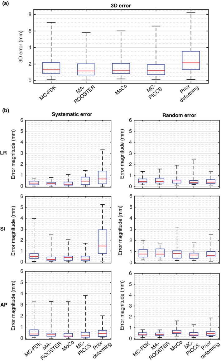
Translation error in planning target volume position for the five methods when applied to the simulated dataset presented as boxplots of the (a) three‐dimensional error magnitude and (b) the magnitude of systematic and random LR, SI, and AP error. The systematic and random error was calculated as the mean and standard deviation of the translation error over the ten phases of a four‐dimensional cone‐beam computed tomography reconstruction. [Color figure can be viewed at wileyonlinelibrary.com]
3.3. Varian and Elekta datasets
Figures 8 and 9 show examples of the reconstructions from the five methods when applied to the Varian and Elekta datasets, respectively. The 4D animations are included in the Supplementary Material (Data S6, Data S7, Data S6, and Data S7). The overall observations are similar to that from the simulated dataset. All five methods rendered significant streaking and noise reduction compared to FDK. The reconstructions from MC‐FDK, MA‐ROOSTER, and MC‐PICCS showed smooth natural motion, while the reconstructions from MoCo and the prior deforming methods showed some unnatural warping of the anatomy.
Figure 8.

The end‐inhale phase of the reference reconstruction (fully sampled), conventional Feldkamp–Davis–Kress reconstruction (downsampled), and reconstruction from the five methods for an example case in the Varian dataset. The window level was adjusted in each panel to encompass the 0.5th and 99.5th percentile pixel intensities within . The four‐dimensional animation for this case is included in the Supplementary Material as Data S3.
Figure 9.

The end‐inhale phase of the reference reconstruction (fully sampled), conventional FDK reconstruction (downsampled), and reconstruction from the five methods for an example case in the Elekta dataset. The window level was adjusted in each panel to encompass the 0.5th and 99.5th percentile pixel intensities within . The four‐dimensional animation for this case is included in the Supplementary Material as Data S4.
A few observations differ from that of the simulated dataset. The MC‐PICCS method produced blurrier reconstructions than for the simulated dataset, which may be due to its sensitivity to the regularization parameters. MC‐PICCS also suffered from more pronounced truncation artifacts here, that is, brighter pixels around the superior and inferior sides in the Varian case and around the lateral sides in the Elekta case. Minor truncation artifacts can also be seen in the MA‐ROOSTER reconstruction in the Elekta case. This is because both MA‐ROOSTER and MC‐PICCS rely on repeated forward‐ and backprojections, which are sensitive to mismatch between the reconstructed volume and the forward‐projection due to truncation.
4. Discussion
Pretreatment 4D‐CBCT imaging in radiotherapy increases treatment time and radiation dose. However, improved reconstruction algorithms may reduce the time and dose to levels normally associated with 3D‐CBCT scans. The SPARE Challenge is the first study to systematically investigate 4D‐CBCT reconstruction from a 1‐min scan using state‐of‐the‐art algorithms with a notable amount of clinically realistic data. While only 5 of 20 participated teams completed the challenge, all five methods produced much improved image quality compared to the FDK method, indicating the possibility of shorter 4D‐CBCT scans.
Each of the five methods was found to have its own strengths and weaknesses. MC‐FDK produces image quality similar to that expected from a conventional fully sampled CBCT scan while achieving geometric accuracy close to clinical voxel sizes (1–2 mm) in most cases. Additionally, the reconstruction can be computed on‐the‐fly, making it the only algorithm out of the five that fits into the typical time frame of a standard treatment. However, MC‐FDK uses the 4D‐CT as a prior, and can suffer from notable motion blur when patient anatomy deviates significantly from 4D‐CT. MA‐ROOSTER has the highest fidelity (i.e., image similarity to the ground truth) and geometry accuracy. Despite its reliance on the 4D‐CT prior, it was found to be robust against large CT‐CBCT differences. However, it is susceptible to truncation artifacts due to the iterative forward‐ and backprojection workflow. Both MC‐FDK and MA‐ROOSTER are open source and available from the Reconstruction Toolkit.35 MoCo is the only data‐driven approach out of the five methods, which makes it immune to changes in patient anatomy or artifacts in the 4D‐CT. MoCo retains good geometric accuracy around the PTV, but can exhibit incorrect warping of the tumor shape and the surrounding anatomy due to the understood limitations of the utilized deformable image registration algorithm in proximity to sliding tissue boundaries. MoCo reconstructions also show more streaking artifacts than the other competitors. MC‐PICCS, similar to MA‐ROOSTER, has the best overall fidelity and accuracy while being robust to CT‐CBCT difference despite its reliance on the 4D‐CT prior. It is even more susceptible to truncation artifacts than MA‐ROOSTER. Additionally, it produced blurrier reconstructions in the Varian and Elekta cases than in the simulated cases, possibly indicating that it requires more scenario‐to‐scenario parameter adjustment. The prior deforming method retains the most details in the reconstruction and has the best image quality and HU accuracy, a direct advantage of solving the reconstruction as a deformed version of the 4D‐CT. It has also been shown to work with limited angular view for intrafraction verification,36 which is not possible with the other four methods. However, its accuracy is more sensitive to anatomic changes from CT to CBCT than other methods. Large anatomic changes can lead to unnatural warping of anatomy and degradation of geometric accuracy. For this reason, the prior deforming method was developed primarily for SABR, and may not be well optimized for the non‐SABR cases included in this study where large anatomic changes can be expected due to the large target volume and long interval between CT and CBCT scans. The intention of the SPARE Challenge was not to pick a single best performing method, as it depends on the scenario and perspective. Instead, the goal is to demonstrate and appreciate what can be achieved with a variety of approaches. As a reference, a simple survey from the 15 teams that did not complete the challenge showed a clear overall preference toward the MA‐ROOSTER method in terms of image quality.
It is important to note that the five presented methods are not an exclusive list of top performing 4D‐CBCT reconstruction algorithms. There are potentially many other promising algorithms that are not presented in this paper either due to not having participated or completed the challenge. While this paper may not represent an exhaustive comparison of all 4D‐CBCT reconstruction algorithms, the results do indicate the robustness of the five presented algorithms to consistently yield clinically desirable image quality and accuracy.
The purpose of the SPARE Challenge is also to provide a common dataset for benchmarking future 4D‐CBCT reconstruction algorithms against the five methods reported in this study. The publicly available dataset 37 includes everything provided to the participants (II C), the ground truth and the reference volumes, and MATLAB scripts to perform automatic analysis exactly as conducted in this study.
It should be noted that the host of the SPARE Challenge, Dr Chun‐Chien Shieh, was one of the participants. To ensure access to the ground truth data did not bias or affect the implementation of the MC‐PICCS algorithm, all of the MC‐PICCS reconstructions were computed with automated scripts that are available upon request. In addition, the analysis of the participated results of the submitted algorithms was all quantitative to avoid subjective evaluation of the reconstructed images.
In this challenge, projections in the simulated dataset were simulated from ten‐phase 4D‐CTs, which assumed no intra‐bin motion and that every breath was identical. Participants were asked to apply their reconstruction algorithms on projections that were already sorted using phase binning. As such, the quantitative analysis only provided insight on how different algorithms handle data undersampling due to respiratory binning and irregular breathing, but not the effects of motion blur caused by different binning approaches, intrabin motion, and breath‐to‐breath variation.
There are a few limitations of the SPARE Challenge. Firstly, the CT scans used to generate the simulated dataset were up to 6 weeks apart, which can result in larger CT‐CBCT differences than that observed from a standard course of SABR. Methods that use the 4D‐CT as a prior, especially the prior deforming method, are therefore expected to perform better in actual SABR cases, where 4D‐CBCT is more important than in non‐SABR cases due to the tight PTV margin and high fractional dose. Secondly, the equispaced downsampling strategy adopted for the Varian and Elekta datasets does not mimic the challenge of an actual 1‐min scan, where projections in each respiratory bin are often clustered around certain angles. This limitation explains the less streaky reconstructions in the Varian and Elekta datasets compared to those in the simulated dataset, especially for the conventional FDK and the MoCo methods. A better downsampling approach, which was adopted by Ahmad et al.,38 is to only keep one respiratory cycle of projections within every N cycles to achieve a downsampling factor of 1/N. Finally, there were a couple of limitations regarding the calibration of projection intensity. Projections in the simulated dataset have attenuation values notably above zero due to noise in the underlying CT volumes. In addition, the flat‐field correction factor was not available for the Varian and Elekta datasets. While these limitations are not expected to drastically alter the observations from this study, they should be carefully considered if a future 4D‐CBCT challenge study is to be conducted.
5. Conclusion
The SPARE Challenge represents the first systematic investigation of 4D‐CBCT reconstruction from 1‐min scans. Five of 20 teams, each using a different algorithm, completed the challenges. All five algorithms were able to produce high quality reconstructions from 1‐min half‐fan scans, indicating promises for reducing scan time and imaging dose for 4D‐CBCT scans. The RMS of the 3D target registration error of the top five methods ranged from 1.79 to 3.00 mm. Overall, the MA‐ROOSTER method, which is an iterative approach that uses 4D‐CT‐based DVF to perform temporal regularization, was found to overall yield the best and most consistent image quality and accuracy. The SPARE Challenge dataset and the analysis framework are publicly available for benchmarking future algorithms.
Acknowledgment
We acknowledge the funding support from the Australian Government National Health and Medical Research Council for an Early Career Fellowship APP1120333 and a Senior Principal Research Fellowship, and Cancer Institute New South Wales for an Early Career Fellowship CS00481. The development of the MoCo algorithm was supported in part by a research grant from the National Institutes of Health under award R01CA166119. The development and implementation of the prior deforming algorithm were supported by National Institutes of Health R01‐CA184173 grant. We thank the American Association of Physicists in Medicine, particularly A/Prof Samuel Armato and Dr Keyvan Farahani, for sponsoring and supporting the SPARE Challenge.
Supporting information
Data S1: The 4D animation of the ground truth and reconstructed volumes for the overall best performing case in the simulated dataset
Data S2: The 4D animation of the ground truth and reconstructed volumes for the overall worst performing case in the simulated dataset
Data S3: The 4D animation of the ground truth and reconstructed volumes for one of the cases in the Varian dataset
Data S4: The 4D animation of the ground truth and reconstructed volumes for one of the cases in the Elekta dataset
Data S5: The 4D animation of the ground truth and reconstructed volumes for an additional example in the simulated dataset
Data S6: The 4D animation of the ground truth and reconstructed volumes for an additional example in the Varian dataset
Data S7: The 4D animation of the ground truth and reconstructed volumes for an additional example in the Elekta dataset
References
- 1. Sonke J‐J, Zijp L, Remeijer P, van Herk M. Respiratory correlated cone beam CT. Med Phys. 2005;32:1176–1186. ISSN 2473‐4209. [DOI] [PubMed] [Google Scholar]
- 2. Sweeney RA, Seubert B, Stark S, et al. Accuracy and inter‐observer variability of 3D versus 4D cone‐beam CT based image‐guidance in SBRT for lung tumors. Radiat Oncol. 2012;7:81. ISSN 1748‐717X; https://www.ncbi.nlm.nih.gov/pubmed/22682767 [DOI] [PMC free article] [PubMed] [Google Scholar]
- 3. Nakagawa K, Haga A, Kida S, et al. 4D registration and 4D verification of lung tumor position for stereotactic volumetric modulated arc therapy using respiratory‐correlated cone‐beam CT. J Radiat Res. 2013;54:152–156. [DOI] [PMC free article] [PubMed] [Google Scholar]
- 4. Feldkamp LA, Davis LC, Kress JW. Practical cone‐beam algorithm. J Opt Soc Am A. 1984;1:612–619. http://josaa.osa.org/abstract.cfm?URI=josaa-1-6-612-619 [Google Scholar]
- 5. McKinnon G, Bates R. Towards imaging the beating heart usefully with a conventional CT scanner. IEEE Trans Biomed Eng. 1981;28:123–127. ISSN 0018‐9294. [DOI] [PubMed] [Google Scholar]
- 6. Leng S, Zambelli J, Tolakanahalli R, et al. Streaking artifacts reduction in four‐dimensional cone‐beam computed tomography. Med Phys. 2008;35:4649. [DOI] [PMC free article] [PubMed] [Google Scholar]
- 7. Bergner F, Berkus T, Oelhafen M, et al. An investigation of 4D cone‐beam ct algorithms for slowly rotating scanners. Med Phys. 2010;37:5044–5053. [DOI] [PubMed] [Google Scholar]
- 8. Sidky EY, Pan X. Image reconstruction in circular cone‐beam computed tomography by constrained, total‐variation minimization. Phys Med Biol. 2008;53:4777. ISSN 1361‐6560. [DOI] [PMC free article] [PubMed] [Google Scholar]
- 9. Chen G‐H, Tang J, Leng S. Prior image constrained compressed sensing (PICCS): a method to accurately reconstruct dynamic CT images from highly undersampled projection data sets. Med Phys. 2008;35:660–663. ISSN 0094‐2405; http://www.ncbi.nlm.nih.gov/pmc/articles/PMC2655145/ [DOI] [PMC free article] [PubMed] [Google Scholar]
- 10. Gao H, Li R, Lin Y, Xing L. 4D cone beam CT via spatiotemporal tensor framelet. Med Phys. 2012;39:6943–6946. ISSN 0094‐2405. [DOI] [PMC free article] [PubMed] [Google Scholar]
- 11. Jia X, Tian Z, Lou Y, Sonke J‐J, Jiang SB. Four‐dimensional cone beam CT reconstruction and enhancement using a temporal nonlocal means method. Med Phys. 2019;39:5592–5602. ISSN 0094‐2405. [DOI] [PMC free article] [PubMed] [Google Scholar]
- 12. Hansen DC, S⊘rregardrensen TS. Fast 4D cone‐beam CT from 60s acquisitions. Phys Imaging Radiat Oncol. 2018;5:69. ISSN 2405‐6316; http: #//www.sciencedirect.com/science/article/pii/S2405631617300453 [DOI] [PMC free article] [PubMed] [Google Scholar]
- 13. Rit S, Wolthaus JWH, van Herk M, Sonke J‐J. On‐the‐fly motion‐compensated cone‐beam CT using an a priori model of the respiratory motion. Med Phys. 2009;36:2283–2296. ISSN 2473–4209 [DOI] [PubMed] [Google Scholar]
- 14. Li T, Koong A, Xing L. Enhanced 4D cone‐beam CT with inter‐phase motion model. Med Phys. 2007;34:3688–3695 https://aapm.onlinelibrary.wiley.com/doi/abs/10.1118/1.2767144 [DOI] [PubMed] [Google Scholar]
- 15. Brehm M, Paysan P, Oelhafen M, Kachelriess M. Artifact‐resistant motion estimation with a patient‐specific artifact model for motion‐compensated cone‐beam CT. Med Phys. 2013;40:101913. [DOI] [PubMed] [Google Scholar]
- 16. Bergner F, Berkus T, Oelhafen M, Kunz P, Pan T, Kachelriess M, Autoadaptive phase‐correlated (AAPC) reconstruction for 4D CBCT. Med Phys. 2009;36:5695–5706. ISSN 0094‐2405. [DOI] [PMC free article] [PubMed] [Google Scholar]
- 17. Chen M, Cao K, Zheng Y, Siochi RAC. Motion‐compensated mega‐voltage cone beam CT using the deformation derived directly from 2D projection images. IEEE Trans Med Imaging. 2015;32:1365–1375. ISSN 0278‐0062. [DOI] [PubMed] [Google Scholar]
- 18. Ren L, Zhang J, Thongphiew D, Godfrey DJ, Wu QJ, Zhou S‐M, Yin F‐F. A novel digital tomosynthesis (DTS) reconstruction method using a deformation field map. Med Phys. 2008;35:3110–3115. ISSN 0094‐2405; http://www.ncbi.nlm.nih.gov/pmc/articles/PMC2809715/ [DOI] [PMC free article] [PubMed] [Google Scholar]
- 19. Wang J, Gu X. High‐quality four‐dimensional cone‐beam ct by deforming prior images. Phys Med Biol. 2013;58:231. [DOI] [PubMed] [Google Scholar]
- 20. Park JC, Kim JS, Park SH, Liu Z, Song B, Song WY. Motion‐map constrained image reconstruction (MCIR): application to four‐dimensional cone‐beam computed tomography. Med Phys. 2013;40:121710. [DOI] [PubMed] [Google Scholar]
- 21. Wang J, Gu X. Simultaneous motion estimation and image reconstruction (SMEIR) for 4D conebeam CT. Med Phys. 2016;40:101912. https://aapm.onlinelibrary.wiley.com/doi/abs/10.1118/1.4821099 [DOI] [PubMed] [Google Scholar]
- 22. Mory C, Janssens G, Rit S. Motion‐aware temporal regularization for improved 4D cone‐beam computed tomography. Phys Med Biol. 2016;61:6856 ISSN 0031‐9155. [DOI] [PubMed] [Google Scholar]
- 23. Zhang H, Ma J, Bian Z, Zeng D, Feng Q, Chen W. High quality 4D cone‐beam ct reconstruction using motion‐compensated total variation regularization. Phys Med Biol. 2017;62:3313. [DOI] [PubMed] [Google Scholar]
- 24. Lu J, Guerrero TM, Munro P, et al. Four‐dimensional cone beam ct with adaptive gantry rotation and adaptive data sampling. Med Phys. 2007;34:3520 ISSN 0094‐2405. [DOI] [PubMed] [Google Scholar]
- 25. Fast MF, Wisotzky E, Oelfke U, Nill S. Actively triggered 4D cone‐beam CT acquisition. Med Phys. 2013;40:091909. ISSN 0094‐2405. [DOI] [PubMed] [Google Scholar]
- 26. Cooper BJ, O’Brien RT, Balik S, Hugo GD, Keall PJ. Respiratory triggered 4D cone‐beam computed tomography: a novel method to reduce imaging dose. Med Phys. 2013;40:041901. ISSN 0094‐2405. [DOI] [PMC free article] [PubMed] [Google Scholar]
- 27. O’Brien RT, Cooper BJ, Kipritidis J, Shieh C‐C, Keall PJ. Respiratory motion guided four dimensional cone beam computed tomography: encompassing irregular breathing. Phys Med Biol. 2014;59:579. [DOI] [PubMed] [Google Scholar]
- 28. Hugo GD, Balik S, Keall PJ, Lu J, Williamson JF. A longitudinal four‐dimensional computed tomography and cone beam computed tomography dataset for image‐guided radiation therapy research in lung cancer. Med Phys. 2017;44:762. ISSN 0094‐2405. [DOI] [PMC free article] [PubMed] [Google Scholar]
- 29. Jia X, Yan H, Cervio L, Folkerts M, Jiang SB. A GPU tool for efficient, accurate, and realistic simulation of cone beam CT projections. Med Phys. 2012;39:7368. ISSN 0094‐2405; http://www.ncbi.nlm.nih.gov/pmc/articles/PMC3523889/ [DOI] [PMC free article] [PubMed] [Google Scholar]
- 30. Roman NO, Shepherd W, Mukhopadhyay N, Hugo GD, Weiss E. Interfractional positional variability of fiducial markers and primary tumors in locally advanced non‐small‐ cell lung cancer during audiovisual biofeedback radiotherapy. Int J Radiat Oncol. 2012;83:1566. ISSN 0360‐3016. [DOI] [PubMed] [Google Scholar]
- 31. Wang Z, Bovik AC, Sheikh HR, Simoncelli EP, Image quality assessment: from error visibility to structural similarity. IEEE Trans Image Process. 2004;13:600–612. ISSN 1057‐7149. [DOI] [PubMed] [Google Scholar]
- 32. Klein S, Staring M, Murphy K, Viergever M, Pluim J, Elastix: a toolbox for intensity‐based medical image registration. IEEE Trans Med Imag. 2010;29:196–205. [DOI] [PubMed] [Google Scholar]
- 33. Riblett, MJ , Christensen GE, Weiss E, Hugo GD. Data‐driven respiratory motion compensation for four‐dimensional cone‐beam computed tomography (4D‐CBCT) using groupwise deformable registration. Med Phys. 2018;45:4471. https://aapm.onlinelibrary.wiley.com/doi/abs/10.1002/mp.13133 [DOI] [PMC free article] [PubMed] [Google Scholar]
- 34. Shieh C‐C, Caillet V, Booth J, et al. 4D‐CBCT reconstruction from a one minute scan. In: Engineering and Physical Sciences in Medicine Conference. Hobart, Australia; 2017. [Google Scholar]
- 35. Rit S, Oliva MV, Brousmiche S, Labarbe R, Sarrut D, Sharp GC. The Reconstruction Toolkit (RTK), an open‐source cone‐beam CT reconstruction toolkit based on the Insight Toolkit (ITK), in XVII International Conference on the use of computers in radiation therapy (ICCR 2013), Australian Inst Radiography; Royal Australian & New Zealand Coll Radiologists; Varian Med Syst; Brainlab; Elekta; Australian Govt Initiat, Australian Clin Dosimetry Serv (IOP PUBLISHING LTD, DIRAC HOUSE, TEMPLE BACK, BRISTOL BS1 6BE, ENGLAND, 2014), vol. 489 of Journal of Physics Conference Series, ISSN 1742‐6588, 17th International Conference on the Use of Computers in Radiation Therapy (ICCR), Australasian Coll Phys Scientists & Engineers Med, Melbourne, AUSTRALIA, MAY 06‐09; 2013.
- 36. Ren L, Zhang Y, Yin F‐F. A limited‐angle intrafraction verification (LIVE) system for radiation therapy. Med Phys. 2014;41:020701. https://aapm.onlinelibrary.wiley.com/doi/abs/10.1118/1.4861820 [DOI] [PubMed] [Google Scholar]
- 37. Shieh C‐C, Gonzalez Y, Li B, et al. Dataset for the spare challenge: Spare‐view reconstruction challenge for 4D cone‐beam CT from a one‐minute scan. In: https://image-x.sydney.edu.au/research/spare-challenge/; 2018. [DOI] [PMC free article] [PubMed]
- 38. Ahmad M, Pan T. Target‐specific optimization of four‐dimensional cone beam computed tomography. Med Phys. 2012;39:5683–5696. https://aapm.onlinelibrary.wiley.com/doi/pdf/10.1118/1.4747609 [DOI] [PMC free article] [PubMed] [Google Scholar]
Associated Data
This section collects any data citations, data availability statements, or supplementary materials included in this article.
Supplementary Materials
Data S1: The 4D animation of the ground truth and reconstructed volumes for the overall best performing case in the simulated dataset
Data S2: The 4D animation of the ground truth and reconstructed volumes for the overall worst performing case in the simulated dataset
Data S3: The 4D animation of the ground truth and reconstructed volumes for one of the cases in the Varian dataset
Data S4: The 4D animation of the ground truth and reconstructed volumes for one of the cases in the Elekta dataset
Data S5: The 4D animation of the ground truth and reconstructed volumes for an additional example in the simulated dataset
Data S6: The 4D animation of the ground truth and reconstructed volumes for an additional example in the Varian dataset
Data S7: The 4D animation of the ground truth and reconstructed volumes for an additional example in the Elekta dataset