Abstract
Neuronal mechanisms in nervous systems that keep intersegmental phase lags the same at different frequencies are not well understood. We investigated biophysical mechanisms that permit local pattern-generating circuits in neighboring segments to maintain stable phase differences. We use a modified version of an existing model of the crayfish swimmeret system that is based on three known coordinating neurons and hypothesized intersegmental synaptic connections. Weakly coupled oscillator theory was used to derive coupling functions that predict phase differences between neurons in neighboring segments. We show how features controlling the size of the lag under simplified network configurations combine to create realistic lags in the full network. Using insights from the coupled oscillator theory analysis, we identify an alternative intersegmental connection pattern producing realistic stable phase differences. We show that the persistence of a stable phase lag to changes in frequency can arise from complementary effects on the network with ascending-only or descending-only intersegmental connections.
To corroborate the numerical results, we experimentally constructed phase–response curves (PRCs) for two different coordinating interneurons in the swimmeret system by perturbing the firing of individual interneurons at different points in the cycle of swimmeret movement. These curves provide information about the contribution of individual intersegmental connections to the stable phase lag. We also numerically constructed PRCs for individual connections in the model. Similarities between the experimental and numerical PRCs confirm the plausibility of the network configuration that has been proposed and suggest that the same stabilizing balance present in the model underlies the normal phase-constant behavior of the swimmeret system.
Keywords: central pattern generators, crayfish swimmeret, coupled oscillator theory, phase lags, frequency regulation, phase–response curves
Introduction
Because of body mechanics, effective locomotion in most complex animals requires that movements of different parts of the body maintain a particular phase relative to other parts despite variations in the frequency of these movements. Phase stability is a necessary feature of the motor patterns that drive these movements, and it is a significant outstanding challenge to explain this feature in terms of the properties and interactions of the controlling neurons. Two recent advances in our knowledge of the crayfish swimmeret system have created the possibility of understanding in cellular terms how the crayfish nervous system achieves stable coordination of limb movements during forward swimming.
Each swimmeret is innervated by a pattern-generating module that includes a set of motor neurons, three kinds of nonspiking local interneurons, and three coordinating interneurons that project axons to targets in other modules (Paul and Mulloney, 1985a,b; Namba and Mulloney, 1999; Mulloney and Hall, 2000). These modules drive alternating power stroke and return stroke movements and are, in principle, independent (Murchinson et al., 1993). In practice, their activity is always coordinated despite changes in frequency, with a posterior-to-anterior progression of power strokes that differ in phase by ∼90° between neighboring swimmerets. The coordinating interneurons found in each module fire bursts of impulses at particular phases in each cycle of the activity of that module. These bursts are necessary and sufficient for normal coordination (Namba and Mulloney, 1999).
Skinner and Mulloney (1998) developed a model of the system that produces this anterior-going phase progression and maintains this phase difference despite changes in frequency. It assumes that the pattern-generating core of each module is a local circuit of nonspiking local interneurons and that coordinating axons from other modules synapse with these interneurons. The opportunity to compare the structure of this model with the properties of the coordinating interneurons arose from the observation that perturbing individual coordinating interneurons causes measurable, phase-dependent changes in the output of the target module of the interneuron (Namba and Mulloney, 1999).
In our study of this model we first applied general theories of weakly coupled oscillators (Ermentrout and Kopell, 1984; Kopell and Ermentrout, 1986) to this cellular model to derive coupling functions that predict the phase lags that exist for several patterns of intersegmental connections. [The same formalism has been shown to hold under less restrictive conditions (Kopell, 1988).] Single intersegmental connections coordinated activity in different modules, but the phase lags were unrealistic. When parallel excitatory and inhibitory connections were permitted, the phase lag changed to ∼90°. When both ascending and descending connections were permitted, the phase lag also stabilized near 90° and no longer was affected by changes in frequency over a wide range. The coupling functions computed for each connection explain why.
We then computed phase–response curves (PRCs) for the model with two ascending connections and compared them with PRCs from stimulating individual ascending interneurons. Similarities in these PRCs suggest that these interneurons make connections that have the same properties of those in the model. This suggests that the same mechanisms that achieve stable intersegmental coordination in the model also coordinate limb movements in the crayfish.
Materials and Methods
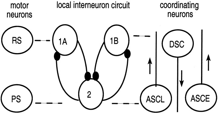
Modeling the local circuit. The motor neurons that control the power and return stroke movements of a swimmeret fire alternating bursts of impulses (Hughes and Wiersma, 1960; Ikeda and Wiersma, 1964). The power stroke (PS) and return stroke (RS) motor neurons (PS and RS in Fig. 1) are driven by a set of nonspiking local interneurons whose synaptic organization is the core of the pattern-generating circuit within each module (Heitler and Pearson, 1980; Paul and Mulloney, 1985a,b; Sherff and Mulloney, 1996). A minimal local pattern-generating circuit consistent with experimental data includes four nonspiking interneurons (Fig. 1): two identical interneurons (combined and labeled 2) that excite PS motor neurons and two other interneurons (labeled 1A and 1B) with different synaptic inputs that excite RS motor neurons. Thus the dynamics of the entire local module can be modeled by a three-cell, nonspiking, local interneuron circuit organized by graded synapses, as developed in Skinner and Mulloney (1998). The depolarized states of cells 1A and 1B are assumed to be in phase with the bursting activity of the RS motor neurons, and the depolarized state of cell 2 is in phase with the bursting activity of the PS neurons.
Fig. 1.
Diagram of the neuronal circuits thought to regulate the activity of motor neurons that innervate a single swimmeret. The module consists of a population of power and return stroke motor neurons (cells PS and RS, respectively), a circuit of nonspiking local interneurons modeled with three cells (cells 1A, 1B, and 2) that are coupled by synaptic inhibition, and three coordinating interneurons, two that project anteriorly (ASCL and ASCE) and one that projects posteriorly (DSC). Dashed lines are drawn between cells that fire in phase. Open circles symbolize either populations of similar neurons (PS, RS, 2) or individual neurons (1A, 1B, ASCE, ASCL, DSC). Connections between neurons that end in a small filled circle symbolize inhibitory synapses. Arrows pointing upward mark ascending axons that project to more anterior segments; the arrow pointing downward marks the descending axon that projects to the more posterior segment. The inhibitory synaptic conductance strength from 2 to 1A (or 1B) in the three-cell local interneuron circuit is double the strength of that from 1A (or 1B) to 2.
The dynamics of each local interneuron of the three-cell circuit are modeled by the following equations:
| Equation 1 |
| Equation 2 |
Here, c is the capacitance of the cellular membrane;v* is the membrane potential of cell *, where * denotes 1A, 1B, or 2; iextis a general imposed current; gl,gca, andgk are maximal conductances of the leak, calcium, and potassium currents, respectively;vl,vca, andvk are the reversal potentials of the leak, calcium, and potassium currents, respectively;m∞ andn∞ are the fractions of open calcium and potassium channels at steady state, respectively; n is the fraction of potassium channels that are actually open; ε1λn is the rate constant of potassium channel opening, and ε1is a small parameter that represents the minimum of λn; v1 and v3 are the voltages at which one-half of the channels are open at steady state; and v2 and v4 are voltages with reciprocals that are the slopes of the voltage dependence of calcium and potassium channel opening at steady state.
The variable s* is a synaptic gating variable controlling a synapse within a local circuit. The * denotes the presynaptic–postsynaptic cells. The parameter (ε2/k(1 −s∞)) is the rate constant ofs*; g is the maximal synaptic conductance, andVinh represents the reversal potential for an inhibitory synapse. The functions∞(Vpre) gives the steady-state synaptic activation value of a postsynaptic cell in a local circuit as a function of the voltage of a presynaptic cell,
| Equation 3 |
The dynamics of s* imply that the synaptic activation variable of a local postsynaptic cell asymptotically approaches the value ofs∞(vpre) when vpre >Vth and then decays slowly (at a rate proportional to (ε2/k)) whenvpre <Vth.
The equations for v1B,n1B, ands1B are the same as those for cell 1A, with all of the A's replaced by B's.
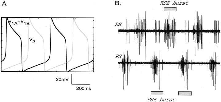
When there is no intersegmental coupling present, the voltages of the local circuit cells exhibit stable “relaxation-type” oscillations: stable limit cycles that are caused by their synaptic interactions. Cells 1A and 1B oscillate together in antiphase to cell 2 (Fig.2A). This is typical behavior of mutually inhibitory cells (Wang and Rinzel, 1992; Skinner et al., 1994); here, cells 1A and 1B inhibit cell 2 with equal strength but do not inhibit each other, and cell 2 inhibits both cells 1A and 1B with equal strength.
Fig. 2.
Alternating depolarizations of local interneurons in the reciprocally inhibitory model circuit. Shown are voltage versus time traces for cells 2 (gray trace) and 1A (= 1B) (black trace).B, Physiological recordings of PS–RS activity corresponding to A and used to measure the phase of the experimental system. The time scale is the same as inA.
Modeling the intersegmental synaptic connections. A separate circuit of coordinating interneurons that originate in each module projects through the minuscule tract (MnT) and couples together swimmerets on neighboring abdominal segments. These interneurons are referred to collectively as MnT interneurons. Three types of MnT coordinating neurons have been identified, namely ASCE, ASCL, and DSC. These neurons are known to fire bursts of impulses in phase with the swimmeret motor pattern and have axons that extend intersegmentally in either the ascending or descending direction (Wiersma and Hughes, 1961;Stein, 1971; Naranzogt et al., 2001) (Fig. 1). The MnT coordinating interneurons are central to the experimental results presented in this paper, but in the computational model they are not defined explicitly as separate cells. Like swimmeret motor neurons, they are driven by graded synaptic currents from local interneurons (Namba and Mulloney, 1999). In this model they are assumed to fire bursts of impulses whenever the nonspiking local interneurons that drive them are depolarized (Fig. 2A). The cell corresponding to cell 2 (Fig. 1) in the posterior ganglion drives the two anterior-projecting connections that correspond to ASCE and ASCL; cell 1A drives the posterior-projection connection that corresponds to DSC. Each connection becomes active whenever the cell that drives it is depolarized (Fig. 3). Thus, in the model, firing by ASCE and ASCL is represented by depolarization of cell 2, and firing by DSC is represented by depolarization of cell 1A or 1B.
Fig. 3.
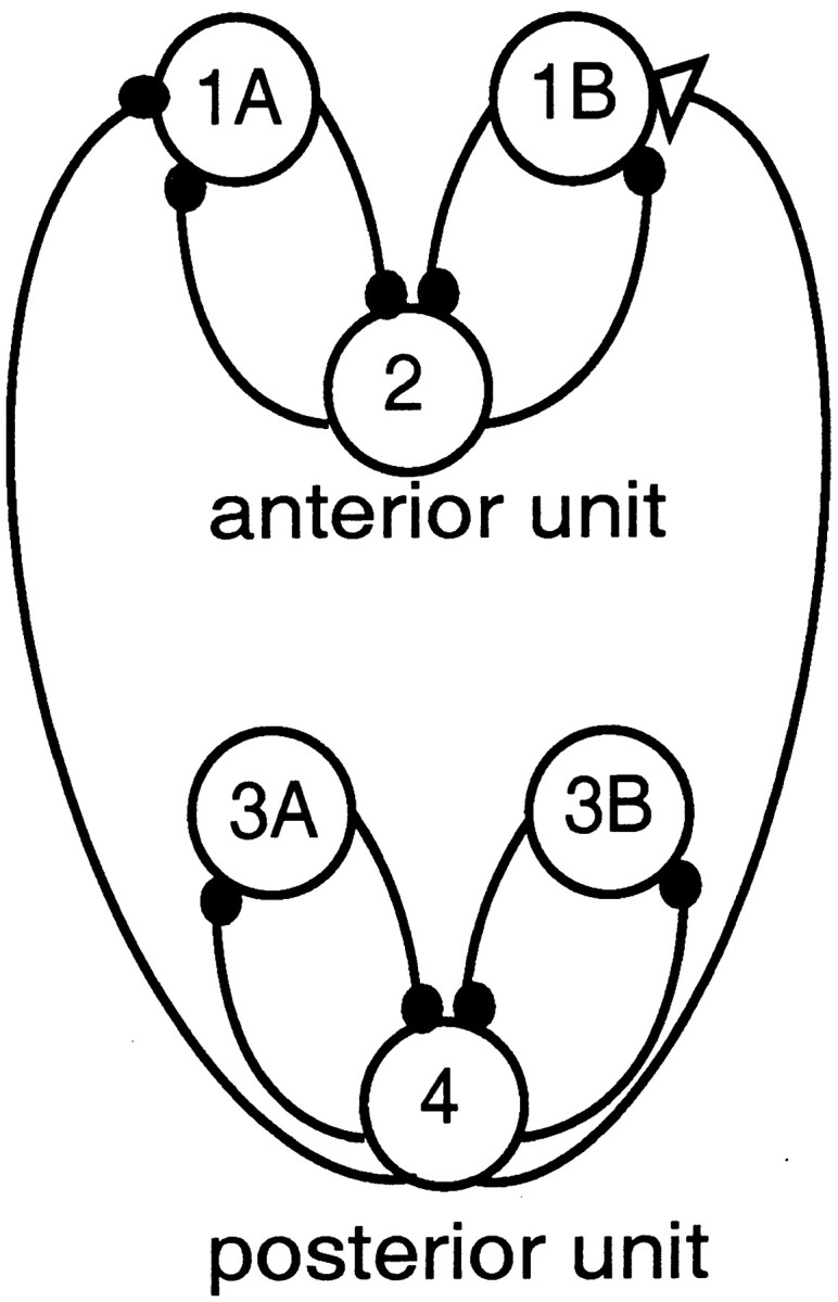
Diagram of a circuit with ascending-only intersegmental connections. The ascending intersegmental connections consist of one excitatory connection (open triangle) and one inhibitory connection (filled circle) from cell 4 (in the posterior unit) to cells 1B and 1A, respectively (in the anterior unit).
We modified the dynamics regulating the intersegmental synapses from that presented by Skinner and Mulloney (1998). In Skinner and Mulloney (1998), intersegmental synapses were modeled with a “spike-mediated transmission threshold” method. Here, intersegmental connections are modeled with instantaneous on and off synapses, as described below. This modification does not alter qualitatively the results of Skinner and Mulloney (1998).
When the intersegmental synapses are present, additional terms of the form:
| Equation 4 |
are added to the voltage equation of the postsynaptic cell, where 0 < δ ≪ 1 represents the small amplitude coupling,vpost is the voltage of the postsynaptic cell, and vpre is the voltage of the forcing cell in the neighboring segment. Also,g , V ,V > 0 are parameters representing the maximal synaptic conductance for an intersegmental synapse, the intersegmental coupling threshold value, and the reversal potential for an intersegmental synapse, respectively. Unlike the local coupling, which is purely inhibitory, the intersegmental coupling can be either inhibitory or excitatory. HenceV can equal eitherVinh orVexc, whereVexc represents the reversal potential for an excitatory synapse. The function U(vpre −V ) turns on and off the intersegmental coupling; it has a value of 1 when the voltage of the neighboring presynaptic cell is above the threshold valueV , but it is zero otherwise.
We study the interactions between a single pair of neighboring segments, as in Skinner and Mulloney (1998). The cells in the anterior unit are referred to as 1A, 1B, and 2, and the corresponding cells in the posterior unit are referred to as 3A, 3B, and 4 (Fig. 3). The equations regulating the cells in the posterior unit are identical to those given above. The intersegmental phase lag of interest is that lag measured between the power stroke motor neurons, i.e., between cells 4 and 2.
Parameter values. The standard values of the parameters used for the equations listed above and throughout the article are, unless otherwise stated, consistent with those used by Skinner and Mulloney (1998) and are as follows. The capacitance, c, of each cellular membrane is set at 1 μF/cm2 (F, farad). The external applied current isiext = 1nA/cm2. The maximal conductances in mS/cm2 (S, siemens) and reversal potentials in mV aregl = 0.2,vl = −60,gca = 0.3,vca = 100,gk = 0.3,vk = −80, g = 0.5,g = 0.3,Vinh = −65 (for both local and intersegmental, V , synapses),Vexc = 0 (when the intersegmental synapse is excitatory), Vth = −50,V = −30,Vslope = 10, v1= −25, v2 = 20, v3 = −30, v4 = 15. Also, k = 3, ε2 = 0.006, δ = 0.0151, and ε1 is from the baseline case in which its value is set at 0.006. Time t is in milliseconds.
To maintain the stable limit cycle oscillations of the local circuits, as shown in Figure 2, we kept fixed most of the parameters listed above for all of the simulations that are presented. We investigated changes in the frequency of the local oscillations by varying the parameter ε1 = 0.006 and changes in intersegmental coupling strengths by varying the parameterg .
All simulations were performed by using G. B. Ermentrout's package for solving ODEs, XPPAUT (Ermentrout, 2002). The usual method of integration was a fourth-order Runge–Kutta method.
Numerical generation of coupling functions (Hfunctions). When the coupling between cells is not too strong, we can derive coupling functions, referred to as H functions, that predict the existence and stability of phase lags between the coupled three-cell local interneuron circuits (Ermentrout and Kopell, 1984; Kopell and Ermentrout, 1986) under various intersegmental coupling configurations.
Each local three-cell circuit that controls a swimmeret can be considered as a local oscillator that has its own intrinsic frequency, ω. The activity of this oscillator can be described by one variable, θ, the phase of this oscillator as it moves around its stable limit-cycle. In a set of similar oscillators that have identical frequencies, ω, and no intersegmental connections, each oscillator,i, is independent, and its phase, θi, is given by the equation θi′ = ω, where θi′ is the derivative of θi with respect to time. In our cellular model of the local swimmeret circuit this formalism can be applied to particular cells. For example, θ2′ = ω describes the phase of cell 2 in its local circuit in the absence of connections from other oscillators.
If we add an intersegmental connection from a cell in one oscillator to a cell in a second oscillator, the phase of the second oscillator will no longer be independent of the phase of the first oscillator. For example, if there is a weak synapse from cell 4 to a cell in the circuit of cell 2 (Fig. 3), then according to the general theory (seeErmentrout and Kopell, 1984; Kopell and Ermentrout, 1986) the dynamics of the system can be described to leading order by:
| Equation 5 |
Here H is a coupling function, the value of which depends on the phase difference between the anterior and posterior oscillators. Higher order corrections, proportional to δ2, are omitted from Equation 5, where recall δ is defined in Equation 4. These equations imply that the posterior oscillator continues to be independent of the anterior oscillator, but the frequency of the oscillator that includes cell 2 now is affected by phase differences between it and the more posterior oscillator. A requirement to derive such coupling functions is that the attraction of each oscillator to its limit cycle is strong when compared with the inter-oscillator coupling; in the present model this attraction is strong because of the amplitude of the local inhibition.
In the case that there is a second ascending intersegmental connection from the posterior oscillator to cells in the anterior oscillator, a second H function is added to the first equation in system 5 such that the sum of the two functions yields the combined effects of the two connections (for the general theory, see again Ermentrout and Kopell, 1984; Kopell and Ermentrout, 1986). We refer to theH function representing all ascending connections asHasc.
In the case that there are new intersegmental connections that project in the descending direction, i.e., from the circuit of cell 2 posteriorly to the circuit of cell 4, then the frequency of cell 4 is no longer independent of θ2, and a new term,Hdesc(θ2 − θ4), is required in the second equation in system 5:
| Equation 6 |
Analytical techniques for calculating the coupling functions are given in the appendix of Ermentrout and Kopell (1991), and we generated the coupling functions by using the H function facility of the XPPAUT software package (Ermentrout, 2002), which is based on the above-mentioned mathematical analysis.
The coupling functions that were generated were used to predict the existence of stable fixed phase lags, φ* = θi − θj, between oscillators i and j. According to the general theory (see Ermentrout and Kopell, 1984; Kopell and Ermentrout, 1986;Skinner et al., 1997), a phase difference, φ*, for whichH(φ*) = 0 and for which the slope of H at φ* is positive, corresponds to a stable phase lag. More specifically, we define the phase difference φ = θ4 − θ2. In the case of ascending-only connections, the rate of change of φ may be computed by using Equation 5,
| Equation 7 |
Therefore, the phase difference φ* for whichHasc(φ*) = 0 corresponds to a fixed phase lag (fixed since φ′ = 0 then), and it is stable ifH′asc(φ*) > 0, because then φ* is an attracting fixed point of the ordinary differential equation (Eq. 7).
When only descending connections are present, the rate of change of φ may be computed as:
| Equation 8 |
In this case the phase difference φ* for whichHdesc(−φ*) = 0 is a stable fixed phase lag if H′desc(−φ*) > 0.
When both ascending and descending connections are present, the rate of change of φ may be computed by using Equation 6 as:
| Equation 9 |
Then, defining the composite function via:
| Equation 10 |
we see that Equation 9 may be written succinctly as:
| Equation 11 |
A fixed phase lag φ* for Equation 11 will be stable ifH′full(φ*) > 0.
Experimental preparation. Our methods are described in detail by Mulloney (1997) and Namba and Mulloney (1999). In summary, crayfish Pacifastacus leniusculus were purchased from local suppliers. At the beginning of an experiment a crayfish was anesthetized by being chilled on ice and then exsanguinated by perfusion. The ventral nerve cord, consisting of abdominal ganglia 1–6, was removed from the abdomen and pinned out dorsal-side up in a Sylgard-lined Petri dish. The sheath was removed from the dorsal side of ganglia A2, A3, A4, and A5. Extracellular electrodes were placed on selected branches of the nerves that innervate swimmerets (Mulloney and Hall, 2000). If the preparation did not express the swimmeret motor pattern spontaneously, it was bathed in 3 μm carbachol (Mulloney, 1997).
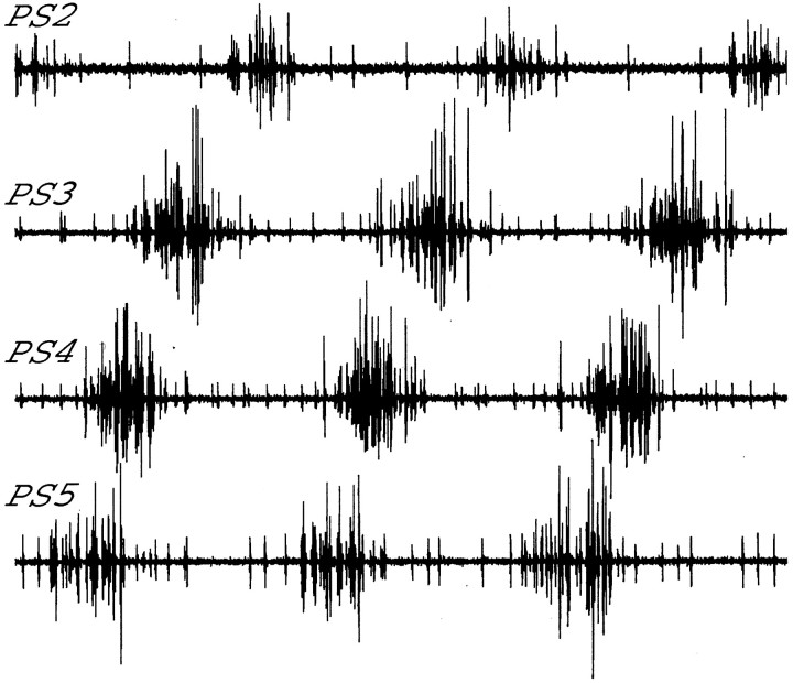
The axons of motor neurons that innervate power stroke muscles are found in the posterior branch of the nerve that innervates each swimmeret; the axons of motor neurons that innervate return stroke muscles are found in the anterior branch (Mulloney and Hall, 2000). Electrodes placed on these two branches will record the entire motor output to the swimmeret (Fig. 2B). To measure the period of the motor pattern, we measured the time between the start of each PS burst and the start of the next PS burst. To calculate the phases in the cycle of activity of the system of PS bursts recorded from a given segment, we defined the start of each cycle as the start of the PS burst in A5 (Fig. 4), and we measured the delay between the start of this PS5 burst and the start of the PS burst in the given segment. Phase was defined as the ratio of this delay to the period of that cycle (Mulloney and Hall, 1987).
Fig. 4.
Experimental recordings of the output from power stroke (PS) motor neurons on neighboring ganglia. These recordings illustrate the characteristic ∼90° intersegmental phase difference.
The axons of the three coordinating interneurons that originate in each module project through the MnT, where their impulses can be recorded with a suction electrode, and continue into the interganglionic connectives (Namba and Mulloney, 1999). Individual MnT coordinating interneurons were penetrated with a sharp microelectrode in the lateral neuropil of the ganglion in which they originated. Each neuron was identified physiologically by the criteria given in Namba and Mulloney (1999). These identifications later were confirmed independently by filling the neuron with Neurobiotin (Vector Labs, Burlingame, CA) and recording the structure of the neurons with the use of a confocal microscope.
Microelectrodes contained 5% Neurobiotin, 1 m KCl, and 10 mm K2PO4, pH 7.4, and had a resistance of 30–50 MΩ. After each experiment the preparation was fixed overnight in 4% paraformaldehyde in PBS. The filled cell was visualized later with streptavidin AlexaFluor 488 (Molecular Probes, Eugene, OR), using the protocol described in detail in Namba and Mulloney (1999).
Phase–response curves (PRCs). We investigated the effects of coupling between neighboring segments in the real and model swimmeret system by using PRCs. PRCs are used rather than Hfunctions because, unlike H functions, they readily can be generated experimentally. PRCs give information about the effect of unidirectional forcing from one oscillating unit to another. In the present case the circuits regulating the motor activity of a swimmeret were considered an oscillating unit (Fig. 1), whose phase was measured in terms of the activity of the PS motor neuron. The phase at which the forced oscillator receives input was plotted on the horizontal axis, and the net change in the period of the forced oscillator was plotted on the vertical axis. We obtained effects of multiple intersegmental connections by summing the PRCs for individual connections; such addition is valid when the coupling is weak.
Unlike H functions, which represent the average of the effects of an ongoing periodic input over a cycle of the recipient oscillator, PRCs measure the effect on spike timing of a specific short input given to an oscillator at different times in its cycle. If the input is sufficiently weak and has a form close to a delta function, the information from the PRC can be used to construct an Hfunction; continuous input is treated as an infinite set of small delta functions, and the H function is computed as a convolution from the “infinitesimal” PRC (Hansel et al., 1995). If the input is not very short or weak, H functions and PRCs are not directly comparable. In our case the input is not very short (lasting the duration of a burst), and the effects from a single perturbation can persist for several cycles. Here we use PRCs only to make direct comparisons between the model and the experimental data.
Experimental generation of PRCs. Once an individual MnT interneuron had been identified in a preparation that was expressing the swimmeret motor pattern continuously, the firing of the neuron was perturbed by periodically injecting pulses of depolarizing current (0.5 nA for ASCE; 0.8 nA for ASCL) through a balanced bridge circuit. The durations of these pulses were approximately the duration of a normal burst. These experimental bursts occurred at frequencies less than one-tenth of the frequency of the on-going swimmeret activity and had no fixed phase relative to this activity. By recording continuously a series of >100 pulses while we recorded motor output from the target ganglion and the firing of the MnT interneuron, we collected a series of perturbations and the changes that they caused to generate a phase–response curve.
To graph the PRC, we first measured the periods of the four PS bursts in the target ganglion that immediately preceded the start of theith current pulse, and we measured the period of the PS cycle during which the pulse began. The mean of these four preceding periods, i, made a good predictor of the expected period of the forced cycle. We then normalized the difference, Difi, between each experimental period Xi and the mean period just preceding it, i, as Difi = (Xi − i)/ i and plotted these normalized differences as functions of the phase in the cycle of the PS neuron in the target ganglion at which the current pulses that caused them began. A horizontal line is drawn aty = 0 to emphasize no change in period.
Numerical generation of PRCs. To compare the model directly to the experimental results, we generated PRCs numerically that correspond to the input from each of the ascending connections in the model (Fig. 3). We began with each local circuit oscillating on its steady-state trajectory independently (Fig. 2A) because there was no intersegmental coupling present. At the beginning of an arbitrary cycle the coupling from cell 4 to the circuit of cell 2 was turned on for one cycle of cell 4 (480 msec). The synapse from cell 4 included a variable delay so that its effects on the anterior circuit would begin at a variable phase in the period of cell 2. This procedure was performed for a sequence of 48 different delays spaced 7.5° apart. For each value of the delay the resulting change in the period of cell 2 was plotted, and we denoted this function as the numerical PRC.
Results
Two quite different levels of analysis, coupled oscillator theory and cellular modeling, have been applied to the swimmeret system, but it has been difficult to join these analyses into a unified understanding of the dynamics of the system. We start with an investigation of why particular patterns of intersegmental connections are able to produce a stable difference in the phase of motor activity in neighboring segments, using the methods of coupled oscillator theory. Because earlier work had established that unidirectional information alone, either “ascending” or “descending” connections, could produce stable phase lags under restricted circumstances (Skinner et al., 1997; Skinner and Mulloney, 1998), we examined the properties of an effective intersegmental circuit that had only ascending connections. We continue with an examination of a similarly effective circuit that has only descending connections. These computational results yield hypotheses about how patterns of inhibitory and excitatory synaptic connections and particular ranges of synaptic strength combine to cause phase differences that do not change despite changes in the frequency of the motor pattern.
Ascending connections: excitation and inhibition combine to create an ∼90° intersegmental phase lag
The modeling work of Skinner and Mulloney (1998) shows that an ∼90° phase lag between cells 4 and 2 is possible with a specific pattern of ascending-only connections from the posterior to the anterior unit. The configuration they propose consists of an ascending inhibitory connection from cell 4 to cell 1A and an ascending excitatory connection from cell 4 to cell 1B, as shown in Figure 3, where the amplitudes of the couplings are small. Recall that cell 4 represents the simultaneous activity of two different axons, ASCE and ASCL. Synapses from these two axons may have opposite effects on the target neurons, depending on the receptors at their respective targets. This architecture is used in this study as a standard case.
We investigated separately the excitatory and inhibitory connections in the ascending-only configuration shown in Figure 3. We numerically evaluated the corresponding H functions from the mathematical theory of weakly coupled oscillators (see Materials and Methods) to show that the combined effects of excitation and inhibition create a stable ∼90° intersegmental phase lag. Here the coupling strengths are set equal to establish a standard case for later comparison.
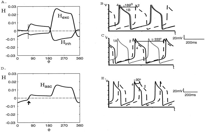
The coupling function Hexc generated in a network containing only excitatory forcing from cell 4 to cell 1B (Fig. 3) is shown in Figure5A. We can infer from the point at which Hexc crosses zero from below that, in the stable steady state, the voltage of cell 4 will oscillate ∼189° ahead of that of cell 2. The simulation shown in Figure 5B verifies this.
Fig. 5.
The coupling functionsHexc(φ),Hinh(φ), andHasc(φ) and voltage traces when only ascending intersegmental connections are present. A, The functions Hexc andHinh generated numerically in circuits containing an ascending excitatory-only connection from cell 4 to 1B and inhibitory-only connection from cell 4 to cell 1A, respectively. The vertical dotted line marks the portions of the functions that sum to zero. B, Voltage versus time traces for cell 4 (black solid curve), cell 2 (black dashed curve), and cell 1B (gray curve) when only the excitatory connection from cell 4 to cell 1B is present.C, Voltage versus time traces for cells 4, 2, and 1A when only the inhibitory connection from cell 4 to cell 1A is present.D, The function Hascgenerated numerically in a network containing both excitatory and inhibitory connections (see Fig. 3). The stable phase lag between cells 4 and 2 occurs at ∼84° for the parameter values of this representative simulation (arrow). E, Voltage versus time traces for cells 4 and 2 when both ascending connections are present.
The function Hinh, generated in a network containing only the inhibitory connection from cell 4 to cell 1A, also is shown in Figure 5A. In this case the voltage of cell 4 will oscillate ∼333° ahead of that of cell 2, as verified by the data shown in Figure 5C.
The sum of the functions Hexc andHinh, denotedHasc, is shown in Figure5D. It crosses zero from below at 84°, which is within 7% of 90° (relative error, i.e., within 6.3°). Thus, the excitation and inhibition combine to cause the voltage of cell 4 to oscillate ∼90° ahead of that of cell 2. The simulation shown in Figure5E verifies this prediction.
We emphasize that the point at whichHasc crosses zero from below depends on the shapes and amplitudes of bothHinh andHexc, not just on their zeros.
Relative intersegmental coupling strengths affect intersegmental phase lag
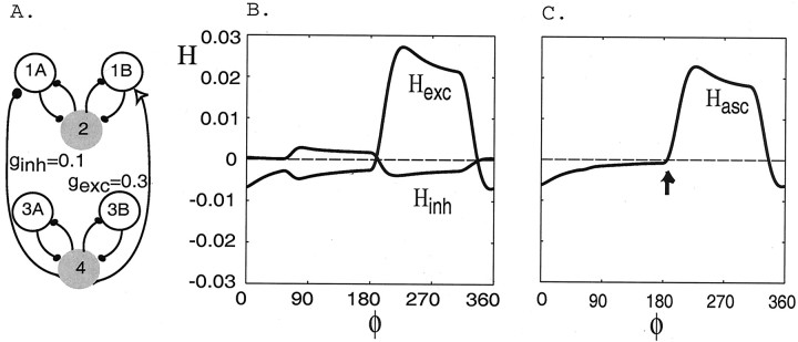
There is a range of values of intersegmental coupling strength over which the intersegmental phase lag remains ∼90°. We useH functions to show this by first fixinggexc = 0.3, as above, so that the function Hexc remains as in Figure5A (redrawn in Fig.6B) and by investigating the effects of both decreasing and increasingginh (from the standard case ofginh = 0.3). When we decreaseginh from 0.3 to 0.16, the intersegmental phase lag remains within 10% of 90° (in particular 99°). For smaller values of ginh the phase lag increases to values outside of a 10% range of 90°. This shift emerges from the effects of changes inginh on the amplitudes of the corresponding functions Hinh. For example, Figure 6B displays a new functionHinh generated withginh = 0.1. The point at whichHinh crosses zero from below and the general shape of the new Hinh are approximately the same as they were in Figure 5A, but the amplitude of this function is smaller. When this new function,Hinh, is added to the functionHexc, the point at which the resulting sum function, Hasc (Fig.6C), crosses zero from below increases to 180°. Moreover, we observe that, when we instead increaseginh (still withgexc = 0.3), the amplitude ofHinh increases; hence the point at which the resulting Hasc crosses zero from below decreases (data not shown).
Fig. 6.
The relative intersegmental connection strengths affect phase lags. A, Schematic of a network containing ascending-only intersegmental connections in which the strengths of the connections differ. B, The coupling functionsHinh and Hexcgenerated numerically in a network containing an ascending inhibitory-only connection from cell 4 to 1A with maximal conductance strength ginh = 0.1 (a decrease from the default value of ginh = 0.3) and an excitatory-only connection from cell 4 to 1B with maximal conductance strength gexc = 0.3, respectively.C, The function Hascgenerated numerically in a circuit containing both inhibitory and excitatory connections with strengths as described in A. In this case the stable phase lag occurs at ∼180° (as indicated with an arrow).
Finally, using the same analysis as above, we see that if we instead keep ginh fixed at 0.3 (as in the standard case) and decrease the relative strength of the ascendingexcitatory connection, then the amplitude ofHexc decreases and the point at which the resulting sum function, Hasc, crosses zero from below decreases (data not shown). Similarly, an increase in the relative strength causes an increase in the value of the zero.
Intersegmental coupling configuration affects intersegmental phase lag
Although many ascending-only network configurations are consistent with the known anatomy of the swimmeret system, most of these will not create an ∼90° intersegmental phase lag (Skinner and Mulloney, 1998). Analysis of the H functions can be used as a tool to determine which configurations may exist in the real swimmeret system. Here we give an example of an ascending-only network configuration that is consistent with the known anatomical information (Wiersma and Hughes, 1961; Stein, 1971; Naranzogt et al., 2001) but show withH functions that it does not create an ∼90° intersegmental phase lag.
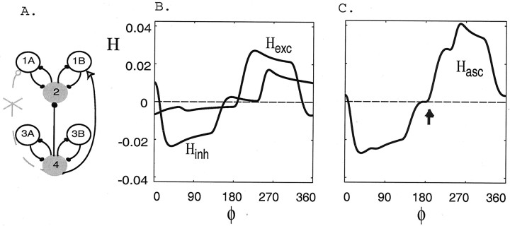
Figure 7B shows the new function Hinh obtained from an inhibitory-only connection from cell 4 to cell 2, rather than to cell 1A (Fig. 7A). This plot shows that the voltage of cell 4 oscillates 153° ahead of that of cell 2. The new functionHinh sums with the previous functionHexc (Fig. 5A) to form a new function Hasc (Fig.7C). The function Hasccrosses zero from below at 173°; hence the stable lag is far from 90°.
Fig. 7.
The pattern of intersegmental coupling connections affects phase lags. A, Schematic of a network containing ascending-only intersegmental connections in which cell 4 inhibits cell 2, rather than cell 1A as in Figure 3, and excites cell 1B.B, The coupling functionsHinh and Hexcgenerated numerically in a network containing an ascending inhibitory-only connection from cell 4 to 2 and an excitatory-only connection from cell 4 to 1B. C, The functionHasc generated numerically in the circuit shown in A. The stable phase lag occurs at ∼173° (arrow).
Descending connections: inhibition and excitation combine to create an ∼90° intersegmental phase lag
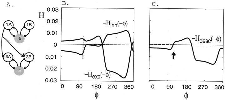
The descending-only configuration we study consists of inhibition from cell 1A to 3A and excitation from cell 1A to 3B (withgexc = 0.3 andginh = 0.3, respectively; see Fig.8A). We note that it is possible for a single descending connection to produce both inhibitory and excitatory effects on neurons if the neurotransmitter it produces has opposite effects on receptors on different neurons in the target segment or if at least one of the effects occurs through a relay neuron. Moreover, this descending-only configuration is consistent with experimental evidence showing that only one coordinating neuron has a descending connection (DSC in Fig. 1).
Fig. 8.
The coupling functions −Hinh(−φ), −Hexc(−φ), and −Hdesc(−φ), plotted as functions of φ, when only descending intersegmental connections are present.A, Schematic of a network containing descending-only intersegmental connections. B, The functions −Hexc(−φ) and −Hinh(−φ) generated numerically in a network containing a descending excitatory-only connection from cell 1A to 3B and inhibitory-only connection from cell 1B to 3A, respectively. The vertical dotted line marks the portion of the functions that sum to zero. C, The function −Hdesc(−φ) generated numerically in a network containing both excitatory and inhibitory connections as shown in A. When both descending connections are present, the stable phase lag occurs at ∼96° for the parameters of this representative simulation (arrow).
The new coupling functions −Hexc(−φ) and −Hinh(−φ) are shown in Figure8B, and their sum, −Hdesc(−φ), is shown in Figure8C. As in the case for the ascending connections, the values at which these functions cross zero from below are near stable phase lags between cells 4 and 2 (see Materials and Methods). Here a stable phase lag between cells 4 and 2 occurs at ∼350° when only the excitatory descending connection is present and at ∼200° when only the inhibitory descending connection is present. The vertical dashed line marks the portions of the functions that sum to zero. The function −Hdesc(−φ) crosses zero from below at φ = 96°, which is within 8% (relative error) of 90°. Hence, we see again that the combination of excitatory and inhibitory connections, now both descending, causes the network to exhibit an ∼90° intersegmental phase lag.
Full network: ascending and descending connections combine to create an ∼90° intersegmental phase lag
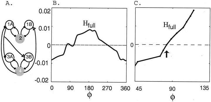
The combined effects of ascending and descending connections (Fig.9A) are obtained by adding the coupling functions Hasc(φ) and −Hdesc(−φ), plotted as functions of φ (see Materials and Methods), each of which has one zero crossing (from below) at ∼90°. The resulting sum function, denotedHfull(φ) and shown in Figure9B, has a very small amplitude over an interval of φ values containing φ = 90, and it actually has three zero crossings near 90°. Hence on the basis of just this leading order function, one might predict that there are two stable phase lags. However, we recall that there are higher order terms, proportional to δ2, that correct the predictions of the leading order function Hfull. These corrections must be taken into account when the amplitude of the leading order H function is so small.
Fig. 9.
The coupling functionHfull(φ) from the fully coupled network (A). B, The leading order functionHfull generated numerically in a network containing both ascending and descending connections as shown inA. C, The functionHfull, including all contributions to frequency changes, not just the leading order ones. There is one stable phase lag at ∼85° for the parameters of this representative simulation (arrow).
Therefore, we computed the full coupling function, which includes all of the contributions to the frequency changes, not just the leading order contribution. We used the method developed in Williams (1992), which is designed to find the full coupling function on those intervals over which it has positive slope only. The result for the representative case is shown in Figure 9C for a range of φ values near 90. The full function has just one zero (at ∼85°) near φ = 90, and it has a positive slope there. Therefore, the analysis that uses coupling functions predicts that the full network maintains a fixed phase lag of ∼90° between cells 4 and 2. Numerical simulations of the full model (data not shown) confirm the presence of this phase lag.
Stability of phase differences despite changes in frequency
We now investigate how changes in the frequency of the oscillation of each cell affect the intersegmental phase lag in the full network (Fig. 9A). To compare with the results of Skinner and Mulloney (1998), we investigated changes in the frequency of the oscillations by varying the rate constant of an outward potassium current via the parameter ε1 (see system 1–2); this is the same parameter used by Skinner and Mulloney. Increasing ε1 from 0.003 to 0.009 linearly increases the frequency of the oscillations from 1 to 3 Hz.
The coupling functions Hasc(φ) and −Hdesc(−φ) for these three frequencies are shown in Figure 10,A and B. We see that there is a range of φ values from ∼45 to 90° over which the functionHasc(φ) qualitatively shifts to the right, and from ∼90 to 135° the function −Hdesc(−φ) qualitatively shifts to the left as the frequency increases. These complementary effects cancel each other out approximately when the functions are summed; hence there is a range of frequencies over which the functionHfull(φ) crosses zero from below at ∼90° (Fig. 10C; for 2 and 3 Hz, i.e., ε1 = 0.006 and ε1= 0.009). Thus when both ascending and descending connections are present, the voltages of cells 4 and 2 are held at an ∼90° phase lag despite changes in frequency. On the other hand, if the frequency is lowered too much, then the phase lag is no longer ∼90° (Fig.10C; for 1 Hz, i.e., ε1 = 0.003). Moreover, the lower boundary of this phase-constant regimen appears to be just below 2 Hz, as is confirmed by the data shown in Figure10C. Also, this boundary point appears to coincide with the transition from the regimen (near 1 Hz) in whichHfull(φ) has three distinct roots, with the middle one nearest 90° being an unstable phase lag to the regimen (at and above 2 Hz), in which there is only one root near 90° and it corresponds to a stable phase lag.
Fig. 10.
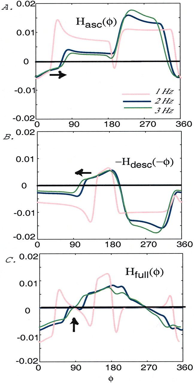
Persistence of the ∼90° phase lag to changes in frequency. A, The coupling functionHasc(φ) for three frequencies, generated in a circuit with an ascending-only intersegmental coupling configuration, as shown in Figure 3. The functionHasc qualitatively shifts to the right as the frequency increases (see arrow), i.e., ε1 increases.B, The coupling function −Hdesc(−φ), for three frequencies, generated in a circuit with a descending-only intersegmental coupling configuration, as shown in Figure 8A. The function −Hdesc qualitatively shifts to the left as the frequency increases (see arrow). C, The coupling function Hfull(φ) for three frequencies, generated in a full network configuration, as shown in Figure 9A. In this case there is a parameter regimen in which the phase lag between cells 4 and 2 remains near 90° despite changes in frequency (see arrow at the points at which the functionHfull crosses zero from below for 2 and 3 Hz). In each figure 1 Hz (ε1 = 0.003) is represented with a red curve, 2 Hz (ε1 = 0.006) is represented with a blue curve, and 3 Hz (ε1 = 0.009) is represented with a green curve.
Phase–response curves: experimental data are consistent with predicted types of ascending connection synapses
As explained in Materials and Methods, we now switch fromH functions to PRCs to show how the results of this computational study bear on the swimmeret system itself. We generated experimental PRCs for each of the ascending coordinating interneurons. We then used the model to generate numerical PRCs for each of the ascending connections and qualitatively compared the two sets of curves. The shapes and intercepts of the experimental and computed curves are similar, and so they support the idea that the stability of intersegmental phase lags in the swimmeret system emerges from the factors we identified by applying coupled oscillator theory.
Two types of MnT coordinating neurons with axons that project anteriorly, ASCE and ASCL in Figure 1, have been identified (Namba and Mulloney, 1999). When the swimmeret system is active, each MnT coordinating neuron fires a burst of impulses at a characteristic phase in each cycle of activity in its home ganglion (Namba and Mulloney, 1999; Naranzogt et al., 2001). These bursts are driven by synaptic currents from neurons within the local pattern-generating circuit, and the firing of each MnT interneuron within one local circuit is independent of the other two (Namba and Mulloney, 1999). As one part of a multi-faceted exploration of MnT interneurons and their targets, B. Mulloney and W. M. Hall (unpublished data) have done phase–response experiments on ASCE and ASCL neurons. Here we show two examples of PRCs from their experiments and compare them with PRCs generated from the model. We find good qualitative agreement between the experimentally generated PRCs for each of these ascending interneurons and the PRCs for each of the ascending connections in the model. These similarities suggest that, like the connections in the model (Fig. 3), one ascending interneuron is excitatory but the other is inhibitory, and the effects of both connections combine to promote a 90° phase lag between the PS bursts in neighboring ganglia.
ASCE coordinating neuron
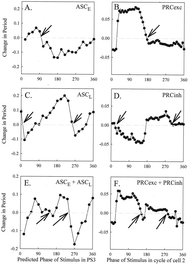
Here we consider the ascending connection originating from the ASCE coordinating neuron in ganglion A4 (see Materials and Methods). Bursts of activity were generated in ASCE at various phases in the cycle of the PS motor neurons in A3 (the next anterior ganglion), referred to as PS3. The difference between the observed period of the PS3 cycle in which the stimulus occurred and the expected period of that cycle was plotted as a PRC (Fig.11A). Data from two experiments were pooled in this example. The main features of this PRC are that there is a brief period of phase delays (i.e., negative changes in period, from ∼0 to 30°) followed by a period of phase advances (i.e., positive changes in period, from ∼30 to 90°) and then a more significant period of phase delays (from ∼90 to 360°). This PRC crosses zero from above just before 90°, as marked with an arrow.
Fig. 11.
Experimental and numerical phase–response curves. A, PRC of ASCE neuron constructed from changes in period of PS3 bursts in response to bursts of impulses in an ASCE neuron from A4. These bursts were triggered by current pulses injected into the ASCE starting at different phases in the cycle of PS3 activity. To construct this curve, first we pooled data from two ASCEs stimulated in different experiments (n = 52 responses) and sorted them by phase. Then phase was partitioned into 20 bins (18° each), the mean of all responses for which the phase fell in each bin was calculated, and these mean responses were plotted as a function of phase. B, PRC generated in a model network containing an excitatory-only connection from cell 4 to 1B. The PRC is the change in the period of cell 2 as a function of the point in its cycle when the excitation from cell 4 arrived. C, PRC of ASCL neuron constructed from changes in period of PS3 bursts in response to bursts of impulses in an ASCL neuron from A4. The means of binned data from one ASCL neuron (n = 122 responses) were calculated and plotted as described inA. D, PRC generated in model network containing an inhibitory-only connection from cell 4 to 1A.E, PRC of the combined ASCE and ASCL connections, created by summing the curves in A and C.F, PRC generated in a model network containing both inhibitory and excitatory connections, as in Figure 3. We note that all of the PRCs have been plotted in terms of 0–360°; to compute the slope of the curves, one must normalize to 0–1. The PRC values inB, D, and F have been multiplied by 10. In adjacent panels, arrows mark corresponding phases at which the experimental and numerical PRCs cross zero from above.
An identical trend of phase advances and delays is seen in the numerically generated PRC corresponding to ascending excitatory input from cell 4 to cell 1B in the model (Fig. 11B) albeit that the phases over which the trends occur are different. This numerical PRC also crosses zero from above in one place (here at ∼169° as marked with an arrow). These strong qualitative similarities between the experimental and numerical PRCs suggest that the ASCE connection indeed may be excitatory, as predicted by the model.
We note that we would not expect perfect agreement between the experimental and numerical results because in the physiological experiments the individual MnT interneurons were being stimulated in parallel with the ongoing firing of the other coordinating axons, whereas in the numerical experiments the ascending connections were activated completely individually.
ASCL coordinating neuron
Next we investigate the effect of the ascending connection originating from the ASCL coordinating neuron in A4. Bursts of impulses were generated in ASCL at various phases in the cycle of PS3. Changes in the period of PS3 are plotted as a PRC (Fig. 11C). The main features of this PRC are that there is a very brief period of phase advances (∼0–10°) followed by a period of phase delays (∼10–90°), then phase advances (∼90–250°), then phase delays (∼250–340°), and finally phase advances (∼340–360°). These features, along with the inherent periodicity of PRCs, suggest that the PRC crosses zero from above in the first quarter of the period of cell PS3, near 10°, and also just before 270°, as marked with arrows.
The experimental PRC shares important qualitative properties with the numerically generated PRC from the model that contains an inhibitory connection from cell 4 to cell 1A (Fig. 11D). The numerical PRC also begins with a very brief period of phase advances, then a more prominent period of phase delays, and then phase advances. This numerical PRC ends with values in the vicinity of zero and with slight phase advances. Like the experimental PRC, this PRC crosses zero from above in two places, here near 10° and just past 270°, as marked with arrows. As expected, there are some quantitative differences between the computed and experimental PRCs, here for inputs arriving late in the cycle of the cells. However, there are enough qualitative similarities between the experimental and numerical PRCs to suggest that the ascending connection made by ASCL may be inhibitory, as predicted by the model.
Effects of ASCE and ASCL coordinating neurons combine to create an ∼90° lag
The experimental data in Figure 11, A andC, show that the observed change in period is relatively small (typically <25%). This suggests that the intersegmental coupling strength is relatively weak and that one can add the PRC data to obtain the combined effect of the two ascending connections. The PRC resulting from the summation of the data from Figure 11, Aand C, is shown in Figure 11E. This PRC begins with a period of phase delays (∼0–60°) followed by a period of phase advances (∼60–140°), then a very short period of phase delays (∼140–180°), then another period of phase advances (∼180–250°), then another period of phase delays (∼250–340°), and finally ending with a period of phase advances (∼340–360°). This PRC crosses zero from above between 90 and 180° (at ∼140°) and just before 270° (at ∼250°), as marked with arrows.
The PRC generated from the model containing both excitatory and inhibitory ascending connections (Fig. 11F) shows similar trends of phase advances and delays as the experimental PRC (Fig. 11E). Furthermore, the numerical PRC also crosses zero from above in at least two places: one between 90 and 180° (at ∼146°) and one just after 270° (at ∼281°), as marked with arrows. We note that the experimental and numerical PRCs have obvious differences in the regions between ∼90 and 140° and between 340 and 360°. In the former region the results are less experimentally stable; hence comparisons with the numerics should be taken less seriously. The differences in the latter region follow from the differences occurring from perturbations arriving late in the cycles of the PS3 experimental neuron as compared with the cell 2 model neuron, when the ASCL and inhibitory connections are perturbed, respectively (Fig. 11C,D), as mentioned above.
Remarkably, the zero crossing near 270° seen in both the experimental and numerical PRCs agrees with the model prediction that excitation and inhibition combine to create an ∼90° phase lag between neighboring segments (measured posterior ahead of anterior segment), and we now briefly explain why. If the effects of a perturbation from one oscillator to another last only one cycle, PRCs can be used to predict values of steady-state phase lags between coupled oscillators. When this assumption holds, PRC theory (Winfree, 1980) predicts that a steady-state phase lag (measured forced ahead of forcing oscillator) exists between the forcing and forced oscillator at phases at which the PRC crosses zero with a slope between −2 and 0. The slopes of the zero crossings near 270° in Figure 11, E and F, are indeed between −2 and 0; because the posterior oscillator is forcing the anterior one, this corresponds to a stable 270° lag of the anterior behind the posterior or a 90° lead of the posterior segment. We note that the effects from the perturbations last more than one cycle, as stated in Materials and Methods. Thus theoretically we rely only on the H functions to make such predictions. However, the good qualitative agreement between this zero crossing and that of the experimental PRC supports the model prediction that the ascending connections alone combine to promote an ∼90° phase lag between the PS motor neurons.
Discussion
The problem we have addressed here is to explain how motor activity in neighboring segments of an animal's nervous system can be coordinated to ensure useful behaviors. The swimmeret circuit model ofSkinner and Mulloney (1998) demonstrated that a pair of axons like the ASCE and ASCL interneurons (Namba and Mulloney, 1999), which conduct information from one pattern-generating module to a second, could produce a phase difference characteristic of movements of neighboring swimmerets, provided that these coordinating axons made the right synapses with the right targets in the model. They did not explain why this pattern of connections was effective. We applied coupled oscillator theory to investigate how this phase difference arises and why it is stable when the output frequency of the system changes.
In the model of Skinner and Mulloney one ascending coordinating axon makes an excitatory connection with its target, but the other makes an inhibitory connection. In coupled oscillator theory the effect of these connections on the phase difference between two segments is described by an H function that depends on the difference between the phases of the two modules. The H functions we calculated numerically for these ascending connections have different shapes. When only one axon was active in the model, the two modules displayed a particular phase difference, but outside the normal range observed in the intact animal. When the two axons were active in parallel, the inhibition and excitation combined to produce a phase lag within the normal range (Fig. 5). These connections simulated chemical synapses without any use-dependent dynamics, and the performance of the model was moderately sensitive to their strengths (Fig. 6). An open question is whether synaptic dynamics like facilitation and depression also might contribute to phase stability (Manor and Nadim, 2001).
Do descending coordinating interneurons work the same way?
Theory predicts that descending coupling alone also should generate a 90° difference in intersegmental phase (Skinner et al., 1997). However, only one MnT axon, DSC, emerges from each module to connect with the next posterior ganglion, and no other descending axons are known to be necessary for coordination (Namba and Mulloney, 1999).Skinner and Mulloney (1998) discovered one pattern of connections that a single descending axon might make that produces an appropriate phase difference. In that circuit, all descending connections were inhibitory. In this paper we described a second pattern of descending connections that also produces an appropriate phase difference (Fig.8A). It more closely resembles the ascending pattern in that it targets the same local interneurons with the same pattern of excitatory and inhibitory synapses. The appropriate test of these two alternatives would be to compare their numerical PRCs with the experimental PRC of a DSC interneuron. However, these experimental data are not yet available. We chose to analyze the model in Figure8A completely because it also produces stable phase differences, because it has both excitatory and inhibitory connections, and because of its symmetry.
When the full complement of two ascending and one descending connections was present in the model (Fig. 9A), the coupling function connecting two modules predicted a stable phase difference of ∼90° (Fig. 9B), the phase difference we also observe in the active crayfish. This ∼90° difference in the full system was stable despite changes over a range of frequencies (Fig. 10). If only ascending or descending connections were present, the phase difference between modules changed systematically with frequency, but the direction of these changes for the ascending and descending connections was different (Fig. 10). Thus the stable phase differences of the Skinner and Mulloney model can be attributed to the different responses of specific excitatory and inhibitory intersegmental connections to changes in frequency. For the case of local circuits connected by a single synapse, S. Jones, T. Kaper, and N. Kopell (unpublished data) used phase plane analysis and singular perturbation theory to identify the geometric mechanisms that hold these circuits in a fixed phase relation. Here we used the theory of weakly coupled oscillators and numerical simulations to show that, when multiple ascending and descending connections are functional (Fig. 9A), they combine to phaselock near 90° despite changes in the system frequency (Fig. 10).
Significance of contributions made by individual coordinating interneurons to the performance of the swimmeret system
In an experimental preparation of the isolated ventral nerve cord (Namba and Mulloney, 1999), it is possible to change the numbers and timing of spikes in one coordinating neuron by stimulating it with pulses of current injected through a microelectrode. If the preparation is expressing the swimmeret motor pattern, these perturbations will affect the phase of the motor pattern in the target ganglion of the stimulated neuron in a manner that depends on phase of the perturbation in the cycle of activity in the target ganglion (Winfree, 1980). We constructed PRCs for ASCE and ASCL axons from experimental data (Fig.11). The PRCs for these two kinds of coordinating axons differed significantly in their shapes and zero crossings, as we would expect if these axons made different connections in the target ganglion. Qualitative similarities between experimentally and numerically generated PRCs (Fig. 11) suggest that the ASCE interneuron produces excitatory effects on targets in the neighboring ganglion while the ASCL interneuron produces inhibitory effects (both testable predictions); hence the mechanism that stabilizes intersegmental phase differences to changes in frequency in the real swimmeret system is the same as the mechanism we have described here.
In this paper and in our earlier theoretical work (Skinner et al., 1997; Skinner and Mulloney, 1998) we have considered only connections between nearest neighboring modules. Although any two pair of neighboring abdominal ganglia, isolated from the rest of the nervous system, can produce the normal intersegmental difference in phase of swimmeret motor activity (Paul and Mulloney, 1986), we know that MnT axons project to more distant ganglia (Naranzogt et al., 2001). This long-range coupling is less effective than coupling between nearest neighbors (Naranzogt et al., 2001) and is not necessary for coordination. Once we know more about the patterns and relative strengths of these connections, it will be possible to extend the models by constructing chains of four modules coupled by connections that span the complete chain.
In the models we have analyzed, coordinating axons connect directly with specific local interneurons in the kernel of each module. Recent anatomical evidence shows that the MnT axons themselves do not project to the locations in which these local interneurons are found (Mulloney and Hall, 2001). Instead, information is relayed from the coordinating axons to the local interneurons in each module by a commissural interneuron that targets only that module. As we learn more about their specific connections, it will be possible to expand the model at the cellular level to include these commissural interneurons. At the systems level this discovery does not affect the model or its predictions.
Footnotes
N.K. and S.J. were supported by National Science Foundation (NSF) Grant DMS9706694. N.K. also was supported by National Institutes of Health R01 MH47150, S.J. by NSF Grant GIG 9631755, and B.M. by NSF Grant IBN 0091284; T.K. was supported in part by NSF Grant DMS-0072596. We thank Wendy M. Hall for contributing experimental data and analysis.
Correspondence should be addressed to Dr. Stephanie R. Jones at her present address: Nuclear Magnetic Resonance Center, Massachusetts General Hospital, 149 Thirteenth Street, Charlestown, MA 02129. E-mail:srjones@nmr.mgh.harvard.edu.
References
- 1. Ermentrout GB. Simulating, analyzing and animating dynamical systems: a guide to XPPAUT for researchers and students (software, environments, and tools), Ed 1. 2002. Society for Industrial and Applied Mathematics; Philadelphia: Software available from http://www.math.pitt.edu/∼bard/xpp/xpp.html [Google Scholar]
- 2.Ermentrout GB, Kopell N. Frequency plateaus in a chain of weakly coupled oscillators, I. SIAM J Math Anal. 1984;15:215–237. [Google Scholar]
- 3.Ermentrout GB, Kopell N. Multiple pulse interactions and averaging in systems of coupled neural oscillators. J Math Biol. 1991;29:195–217. [Google Scholar]
- 4.Hansel D, Mato G, Meunier C. Synchrony in excitatory neural networks. Neural Comput. 1995;7:307–337. doi: 10.1162/neco.1995.7.2.307. [DOI] [PubMed] [Google Scholar]
- 5.Heitler AC, Pearson KG. Nonspiking interactions and local interneurons in the central pattern generator of the crayfish swimmeret system. Brain Res. 1980;187:206–211. doi: 10.1016/0006-8993(80)90506-5. [DOI] [PubMed] [Google Scholar]
- 6.Hughes GM, Wiersma CAG. The coordination of swimmeret movements in the crayfish, Procambarus clarkii. J Exp Biol. 1960;37:657–670. [Google Scholar]
- 7.Ikeda K, Wiersma CAG. Autogenic rhythmicity in the abdominal ganglion of the crayfish: the control of swimmeret movements. Comp Biochem Physiol. 1964;12:107–115. doi: 10.1016/0010-406x(64)90053-2. [DOI] [PubMed] [Google Scholar]
- 8.Kopell N. Toward a theory of modeling central pattern generators. In: Cohen A, Grillner S, Rossignol S, editors. Neural control of rhythmic movement. Wiley; New York: 1988. pp. 369–413. [Google Scholar]
- 9.Kopell N, Ermentrout GB. Symmetry and phaselocking in chains of weakly coupled oscillators. Commun Pure Appl Math. 1986;39:623–660. [Google Scholar]
- 10.Manor Y, Nadim F. Synaptic depression mediates bistability in neuronal networks with recurrent inhibitory connections. J Neurosci. 2001;21:2460–2470. doi: 10.1523/JNEUROSCI.21-23-09460.2001. [DOI] [PMC free article] [PubMed] [Google Scholar]
- 11.Mulloney B. A test of the excitability-gradient hypothesis in the swimmeret system of crayfish. J Neurosci. 1997;17:1860–1868. doi: 10.1523/JNEUROSCI.17-05-01860.1997. [DOI] [PMC free article] [PubMed] [Google Scholar]
- 12.Mulloney B, Hall WM. The PD programs: a method for the quantitative description of motor patterns. J Neurosci Methods. 1987;19:47–59. doi: 10.1016/0165-0270(87)90020-3. [DOI] [PubMed] [Google Scholar]
- 13.Mulloney B, Hall WM. Functional organization of crayfish abdominal ganglia. III. Swimmeret motor neurons. J Comp Neurol. 2000;419:233–243. doi: 10.1002/(sici)1096-9861(20000403)419:2<233::aid-cne7>3.0.co;2-y. [DOI] [PubMed] [Google Scholar]
- 14.Mulloney B, Hall WM. Contributions of intersegmental interneurons to normal coordination of crayfish swimmerets. Abstr Soc Neurosci. 2001;27:730.13. [Google Scholar]
- 15.Murchinson D, Chrachri A, Mulloney B. A separate local pattern-generating circuit controls the movement of each swimmeret in crayfish. J Neurophysiol. 1993;70:2620–2631. doi: 10.1152/jn.1993.70.6.2620. [DOI] [PubMed] [Google Scholar]
- 16.Namba H, Mulloney B. Coordination of limb movements: three types of intersegmental interneurons in the swimmeret system and their responses to changes in excitation. J Neurophysiol. 1999;81:2437–2450. doi: 10.1152/jn.1999.81.5.2437. [DOI] [PubMed] [Google Scholar]
- 17.Naranzogt T, Hall WM, Mulloney B. Limb movements during locomotion: tests of a model of an intersegmental coordinating circuit. J Neurosci. 2001;21:7859–7869. doi: 10.1523/JNEUROSCI.21-19-07859.2001. [DOI] [PMC free article] [PubMed] [Google Scholar]
- 18.Paul DH, Mulloney B. Local interneurons in the swimmeret system of the crayfish. J Comp Physiol [A] 1985a;156:489–502. [Google Scholar]
- 19.Paul DH, Mulloney B. Nonspiking local interneurons in the motor pattern generator of the crayfish swimmeret. J Neurophysiol. 1985b;54:28–39. doi: 10.1152/jn.1985.54.1.28. [DOI] [PubMed] [Google Scholar]
- 20.Paul DH, Mulloney B. Intersegmental coordination of swimmeret rhythms in isolated nerve cords of crayfish. J Comp Physiol [A] 1986;158:215–224. [Google Scholar]
- 21.Sherff CM, Mulloney B. Tests of the motor neuron model of the local pattern-generating circuits in the swimmeret system. J Neurosci. 1996;16:2839–2859. doi: 10.1523/JNEUROSCI.16-08-02839.1996. [DOI] [PMC free article] [PubMed] [Google Scholar]
- 22.Skinner FK, Mulloney B. Intersegmental coordination of limb movements during locomotion: mathematical models predict circuits that drive swimmeret beating. J Neurosci. 1998;18:3831–3842. doi: 10.1523/JNEUROSCI.18-10-03831.1998. [DOI] [PMC free article] [PubMed] [Google Scholar]
- 23.Skinner FK, Kopell N, Marder E. Mechanisms for oscillation and frequency control in reciprocally inhibitory model neural networks. J Comput Neurosci. 1994;1:69–87. doi: 10.1007/BF00962719. [DOI] [PubMed] [Google Scholar]
- 24.Skinner FK, Kopell N, Mulloney B. How does the crayfish swimmeret system work? Insights from nearest neighbor coupled oscillator models. J Comput Neurosci. 1997;4:151–160. doi: 10.1023/a:1008891328882. [DOI] [PubMed] [Google Scholar]
- 25.Stein PSG. Intersegmental coordination of swimmeret motor neuron activity in crayfish. J Neurophysiol. 1971;34:310–318. doi: 10.1152/jn.1971.34.2.310. [DOI] [PubMed] [Google Scholar]
- 26.Wang X-J, Rinzel J. Alternating and synchronous rhythms in reciprocally inhibitory model neurons. Neural Comput. 1992;4:84–97. [Google Scholar]
- 27.Wiersma CAG, Hughes GM. On the functional anatomy of neuronal units in the abdominal cord of the crayfish, Procambarus clarkii. J Comp Neurol. 1961;116:209–228. doi: 10.1002/cne.901160209. [DOI] [PubMed] [Google Scholar]
- 28.Williams TL. Phase coupling in simulated chains of coupled oscillators representing the lamprey spinal cord. Neural Comput. 1992;4:546–558. [Google Scholar]
- 29.Winfree AT. The geometry of biological time. Springer; Heidelberg: 1980. [Google Scholar]


