Abstract
Surface infrared thermography, hotwire anemometry, and thermocouple surveys were performed on two new film cooling hole geometries: spiral/rifled holes and fluidic sweeping holes. The spiral holes attempt to induce large-scale vorticity to the film cooling jet as it exits the hole to prevent the formation of the kidney shaped vortices commonly associated with film cooling jets. The fluidic sweeping hole uses a passive in-hole geometry to induce jet sweeping at frequencies that scale with blowing ratios. The spiral hole performance is compared to that of round holes with and without compound angles. The fluidic hole is of the diffusion class of holes and is therefore compared to a 777 hole and Square holes. A patent-pending spiral hole design showed the highest potential of the non-diffusion type hole configurations. Velocity contours and flow temperature were acquired at discreet cross-sections of the downstream flow field. The passive fluidic sweeping hole shows the most uniform cooling distribution but suffers from low span-averaged effectiveness levels due to enhanced mixing. The data was taken at a Reynolds number of 11,000 based on hole diameter and freestream velocity. Infrared thermography was taken for blowing ratios of 1.0, 1.5, 2.0, and 2.5 at a density ratio of 1.05. The flow inside the fluidic sweeping hole was studied using 3D unsteady RANS.
INTRODUCTION
Commercial aviation gas turbine engines produce thrust by efficiently burning fuel in a combustor, accelerating the results of combustion through turbine stages that drive a fan and compressor stages. The fan produces most of the thrust of a high bypass ratio aviation engine while the compressor ensures a pressure rise to make the combustion process more efficient. The fluid exiting the combustor can reach temperatures well in excess of the component thermal limits in the high pressure turbine (HPT) section. High overall pressure ratios as well as increased turbine inlet total temperatures are expected to be the hallmarks of future civil aviation engines. In general, an increase in compressor pressure ratio leads to higher thermal efficiency. This is accompanied by an increase in the temperature exiting the combustor and entering the high pressure turbine. In order to cool the surfaces of components in the HPT, part of the air from the compressor is bled away and fed through internal passages to the HPT where the relatively cooler fluid is injected through discrete holes onto the surface of the hot components. This cooling fluid, when fed into the rotor, has work done on it by the rotor instead of being used to turn the HPT blades. Every 5% of compressor air used for cooling translates to a 1% reduction in fuel burn.
Within the next 20 years, in a push to increase the thermodynamic efficiency of the engine core, turbine inlet temperatures will likely rise beyond 2400K. Reduced cooling in a relative sense will provide major fuel burn savings but will require the use of high temperature metals or ceramic matrix composites coupled with improved cooling schemes - better internal cooling, better film effectiveness (if film cooling is present) and more uniform film coverage. A plethora of novel hole shapes ranging from helical holes to fractal networks can be found in the literature and the ever growing body of patents. The state of the art, however, is quite difficult to improve upon, namely, diffusion-type holes. There is a tradeoff between benefit for cooling and cost to machine the holes. The advent of additive manufacturing brings new hope to several novel cooling hole shapes that might otherwise have been relegated to oblivion.
Conventional film cooling shapes consist of streamwise circular cylindrical holes, cylindrical holes at compound angles (angled to the freestream and the spanwise direction), and diffusion-type holes. The cylindrical holes work well at relatively low blowing ratios (the ratio of the coolant flow rate to freestream flow rate), BR <1.0. A comprehensive review of the parametric effects on film cooling is provided in [1] and [2]. In summary, at low blowing ratios (and low density ratio), an increase in turbulence intensity leads to a deterioration of cooling effectiveness due to enhanced jet-freestream mixing in the near-hole region and increased losses. At high blowing ratios, turbulence helps to provide cooling to the otherwise starved surface by mixing the lifted-off coolant jet with the surrounding hot gas [3]. A similar trend is observed for surface roughness [1]. Hole length to diameter (L/D) ratio influences the trajectory of the cooling jet as it emerges from the hole [4]. For concepts that involve modifications to the coolant jet trajectory, it is therefore important to model the effect of L/D to determine performance at engine-realistic L/D values. Another critical parameter is the pitch to diameter ratio (P/D). At small P/D, coolant is wasted due to the mixing of neighboring jet streams, while at large P/D there are regions between cooling holes where there is no cooling. It is important to space cooling holes in a manner that allows for just enough cooling hole interaction that the maximum temperature between holes does not exceed material limits.
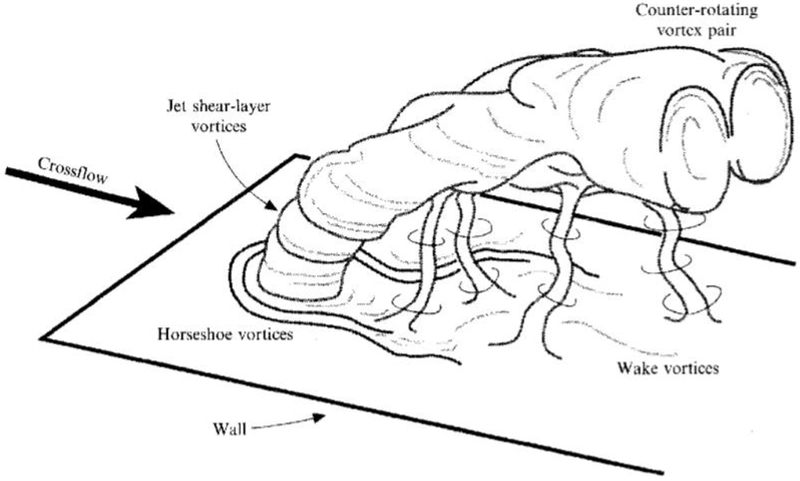
Several holes are used in order to distribute the coolant evenly across the surface. However as the blowing ratio increases, coolant jet lift-off is likely, and the coolant cannot provide adequate protection to the vane surface. Figure 1 shows the general features of a jet in crossflow [5]. The flow emanating from the round holes is enveloped by the freestream, creating a pair of counter-rotating kidney shaped vortices that entrains the hot freestream gas, transports it under the film cooling jet and thus attenuates the cooling effectiveness [6, 7].
FIGURE 1. VORTICAL STRUCTURES FOR JET-IN-CROSSFLOW [5].
Cartoon depicting, four types of vortical structure associated with the transverse-jet near field: jet shear-layer vortices at the perimeter of the bending jet, the developing, counter-rotating vortex pair, horseshoe vortices on the wall. and wake vortices extending from the wall to the jet.
The class of hole shapes referred to as diffusion holes can be defined as holes having an exit to inlet area greater than unity. This includes a wide variety of holes such as anti-vortex, laidback, fan-shaped, Nekomimi, dumbbell, sister holes, etc. A review of these hole shapes can be found in [8] and [9]. Diffusion-type shaped holes reduce the kidney shape effect, can stay better attached to the surface, and can spread the coolant over a wider area [9]. This is due to the increased exit area (diffusion) that reduces the jet exit velocity and therefore reduces the blowing ratio. The trailing edge of the hole makes a more acute angle with the freestream that allows the jet to stay attached to the surface at higher blowing ratios. Lateral angles if present provide for improved jet spreading. Therefore, for the same mass flow through a cylindrical hole, the diffusion type holes can provide more uniform and higher values of film effectiveness. A description of relevant parameters and film cooling correlations for fan-shaped holes can be found in [10].
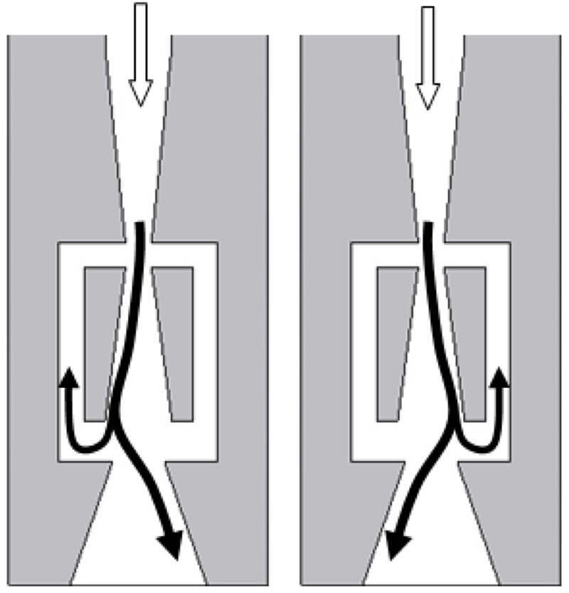
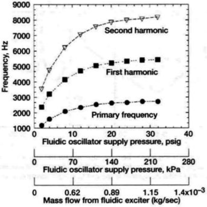
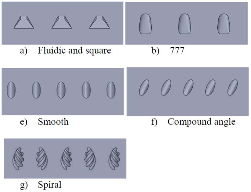
This paper introduces two new classes of cooling holes. The first is a fluidic actuator [11–13] that combines the effects of internal cooling, diffusion type holes and sweeping jets. Fluidic sweeping jet actuators with no moving parts, such as that shown in figure 2, are based on bi-stable states of a jet of fluid in a cavity caused by a specially designed feedback path. A jet of fluid attaches to one of the two sides of a surface due to “wall attachment”; commonly known as the “Coanda” effect. The pressure distribution in the cavity is accordingly changed and the feedback channel transmits this pressure differential back to the point of the jet separation thus deflecting the jet to the other side. This cycle is repeated on the other side of the cavity through the feedback channel on the right thus producing an oscillating jet at the exit of the cavity. A slight modification at the exit of the actuator (a splitter plate) is required to produce alternately pulsing jets at the exit instead of a single sweeping jet. Thus, these devices do not need external signals or actuation to produce oscillating jets. Frequencies from 1–10 kHz have been obtained with meso-scale (nozzle sizes in the range of 200 microns — 1mm) fluidic actuators with very low mass flow rates of the order of (10−3 Kg/sec) [12], Figure 3 shows the frequency as a function of mass flow characteristics of a fluidic actuator (1.69 mm x 0.95 mm exit area) used by Raman et al [13] in their experiments on cavity noise control. The sweeping hole, due to its diffusion type behavior, is compared to a “777” generic shaped hole [14] and a square flared hole.
FIGURE 2.
SCHEMATIC AND FUNCTIONING OF A FLUIDIC SWEEPING ACTUATOR
FIGURE 3.
FREQUENCY AND MASS FLOW CHARACTERISTICS OF A SWEEPING JET [12, 13]
The second hole shape introduced is a patent-pending NASA designed spiraling or rifled hole, in which the flow exiting the hole will have a rotation and distribute the coolant differently than a conventional cylindrical hole. This hole shape is compared to smooth cylindrical holes with and without compound angles. It should be noted that these rifled holes can be created in the manner of diffusion shaped holes, but for the present study the focus is on capturing the effects of rifling on the kidney shaped vortices and on the interaction of rifled holes with each other for various configurations.
For this study, infrared thermography was taken to provide surface temperature and effectiveness measurements. Thermocouple and hotwire anemometry surveys were taken at discreet cross sections to see the flow patterns coming out of the cylindrical round and spiraled holes, and compared with results using particle image velocimetry (PIV).
NOMENCLATURE
| BR | blowing ratio = (ρU)c / (ρU)∞ |
| D | diameter of film cooling hole |
| L | length of hole |
| P | spacing between film cooling holes |
| T | temperature |
| U | velocity component in streamwise direction |
| x | streamwise distance from hole leading edge |
| y | spanwise distance from hole centerline |
| z | vertical distance from tunnel floor |
| η | film cooling effectiveness |
| θ | dimensionless air temperature |
| ρ | Density |
Subscripts
| aw | adiabatic wall |
| c | coolant |
| R∞ | freestream recovery |
EXPERIMENTAL SETUP
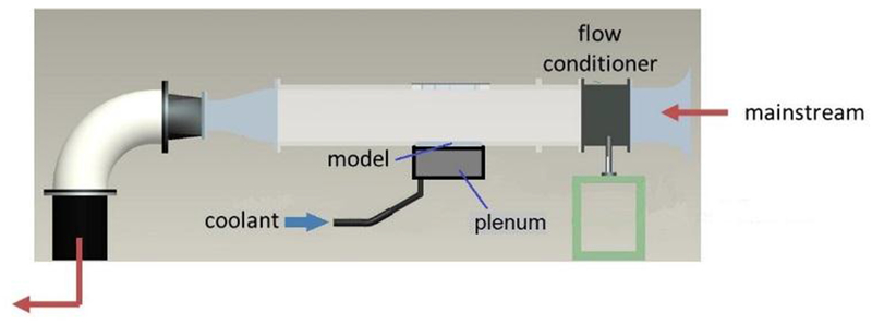
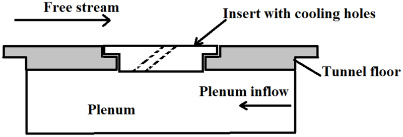
The test facility is shown in Figure 4. The tunnel consists of an aluminum bellmouth, flow conditioning screens, and a square acrylic section 8.2” wide with 0.75” thick walls. The tunnel was connected to a central exhaust system downstream that pulled room air through. The test section pieces were attached to the floor of the tunnel. The test section floor piece used inserts with a varying number of holes and hole shapes, and were either machined from acrylic (777, Square, and Fluidic inserts) or fabricated from ABSplus thermoplastic in a 3-D printer.
FIGURE 4.
TEST FACILITY
Figure 5 shows the tunnel test section floor configuration. The thermal conductivity of the ABSplus thermoplastic is 0.17 W/m/K, which is similar to acrylic with a nominal value of 0.18 W/m/K. The coolant holes were inclined at 30 degrees to the horizontal surface, and nominal hole diameter was 0.25 inches for infrared thermography data and 0.75 inches for the temperature and flow field survey data. The nominal diameter is the diameter at the throat that provides the same area at the throat for a hole shape as for a smooth cylindrical hole. The hole spacing P/D was 3 or 6, depending on the test piece being used. A lid directly above the test section floor piece was used for viewing and for actuator traversing support. Tunnel flow was at ambient conditions with a blade-realistic Reynolds number based on hole diameter and freestream velocity of 11,000. Freestream turbulence was measured to be 1.5% at the inlet to the test section. Coolant flow was provided by blowing pressurized air through a flow meter and into a plenum attached to the underside of the test section floor plate. When cooled air was required for thermocouple and infrared measurements, the coolant passed through copper tubing that was coiled inside an ice-water tank, providing plenum temperatures near 40° for high cooling flow rates and near 50° for low cooling flow rates.
FIGURE 5.
TEST SECTION FLOOR SHOWING INSERT FOR COOLING HOLE
A PC-based data acquisition system was used to acquire data from pressure transducers and thermocouples. The tunnel flow rate was measured from a total pressure probe placed upstream of the test section and static pressure taps located on the sidewalls. Freestream temperature was measured with a thermocouple located upstream of the holes near the total pressure probe. Coolant conditions were measured with static pressure taps and thermocouples inside the plenum. Steady state thermocouple and hot-wire anemometry surveys were taken at cross sectional planes at x/D = 2, 4, and 6, where x is the distance from the leading edge of hole, and along the centerline in the streamwise direction. An actuator system was used to position the probe in the tunnel. Infrared measurements were acquired with a high resolution infrared camera, with images stored on a laptop computer.
Flow survey measurements were obtained using a two channel, constant temperature hot-wire anemometer system, averaged for 3 seconds at a frequency of 50 kHz. Two cross-flow type X-wire probes were used for two velocity component measurements, one obtaining u-v components and the other obtaining u-w components. The probes were calibrated in the test section by being placed in the center of the tunnel, varying the tunnel flow rate, and recording the voltages for each wire. Temperature survey measurements were obtained with an open-ball type E thermocouple, averaged for 3 seconds at a rate of 5 kHz. An uncertainty analysis performed on the flow and temperature measurements showed the data to be nominally within 3%.
As previously stated, the objective of this paper is to investigate two new film cooling hole geometries, the Fluidic sweeping holes and the spiral holes. Since these two designs are fundamentally different, each will be compared to a relevant class of holes. The Fluidic will be compared to diffusion-type holes including a generic shaped hole and a square flared hole. The spiral design will be compared to smooth cylindrical holes both with and without compound angles. These hole shape exits are shown in Figure 6, and the conditions at which they were tested are listed in Tables 1 and 2.
FIGURE 6.
HOLE EXIT SHAPES
TABLE 1.
PARAMETERS FOR DIFFUSION-TYPE HOLES (P/D=6. L/D=12, RE=11000. DR=1.051)
| Hole Geometry | Nominal Blowing Ratio | Coolant Exit Temperature (°F) | Freestream Recovery Temperature (°F) | Uncertainty in η (%) | Uncertainty (°F) |
|---|---|---|---|---|---|
| Fluidic | 1 | 51.4 | 74.9 | 0.2 | 0.05 |
| Fluidic | 1.5 | 50.5 | 75.2 | 0.2 | 0.05 |
| Fluidic | 2 | 48.6 | 74.6 | 0.2 | 0.05 |
| Fluidic | 2.5 | 47.6 | 75.0 | 0.2 | 0.05 |
| 777 | 1 | 53 | 75.4 | 0.2 | 0.05 |
| 777 | 1.5 | 52.4 | 75.5 | 0.2 | 0.05 |
| 777 | 2 | 50.9 | 74.6 | 0.2 | 0.05 |
| 777 | 2.5 | 50.3 | 75.4 | 0.2 | 0.05 |
| Square | 1 | 53.9 | 72.2 | 1.1 | 0.2 |
| Square | 1.5 | 52.5 | 72.3 | 1.0 | 0.2 |
| Square | 2 | 50.2 | 72.2 | 0.9 | 0.2 |
| Square | 2.5 | 53.5 | 74.9 | 0.9 | 0.2 |
TABLE 2.
TABLE OF PARAMETERS FOR NON-DIFFUSION TYPE HOLES (L/D=4, DR=1.05)
| Hole Geometry | Nominal Blowing Ratio | Coolant Exit Temperature (°F) | Freestream Recovery Temperature (°F) | P/D | Re | Uncertainty in η (%) | Uncertainty (°F) |
|---|---|---|---|---|---|---|---|
| Smooth Circular | 1.0 | 54.0 | 73.4 | 6 | 11000 | 1.0 | 0.20 |
| Smooth Circular | 1.5 | 53.6 | 75.7 | 6 | 11000 | 0.9 | 0.20 |
| Smooth Circular | 2.0 | 53.1 | 75.9 | 6 | 11000 | 0.9 | 0.20 |
| Smooth Circular | 2.5 | 52.6 | 76.1 | 6 | 11000 | 0.9 | 0.20 |
| Smooth Circular | 2.0 | 53.4 | 75.9 | 3 | 7400 | 0.9 | 0.20 |
| Smooth Compound Angle | 1.0 | 50.3 | 71.8 | 6 | 11000 | 0.9 | 0.20 |
| Smooth Compound Angle | 1.5 | 48.1 | 72.0 | 6 | 11000 | 0.8 | 0.20 |
| Smooth Compound Angle | 2.0 | 48.0 | 72.4 | 6 | 11000 | 0.8 | 0.20 |
| Smooth Compound Angle | 2.5 | 50.1 | 74.4 | 6 | 11000 | 0.8 | 0.20 |
| Smooth Compound Angle | 2.0 | 47.9 | 72.3 | 3 | 7400 | 0.8 | 0.20 |
| Spiral Same Direction | 1.0 | 57.3 | 73.7 | 6 | 11000 | 0.3 | 0.05 |
| Spiral Same Direction | 1.5 | 52.6 | 72.3 | 6 | 11000 | 0.3 | 0.05 |
| Spiral Same Direction | 2.0 | 49.2 | 72.1 | 6 | 11000 | 0.2 | 0.05 |
| Spiral Same Direction | 2.5 | 45.3 | 72.0 | 6 | 11000 | 0.2 | 0.05 |
| Spiral Alternating Direction | 1.0 | 49.7 | 71.0 | 6 | 11000 | 0.2 | 0.05 |
| Spiral Alternating Direction | 1.5 | 47.3 | 71.5 | 6 | 11000 | 0.2 | 0.05 |
| Spiral Alternating Direction | 2.0 | 46.9 | 71.8 | 6 | 11000 | 0.2 | 0.05 |
| Spiral Alternating Direction | 2.5 | 46.9 | 71.9 | 6 | 11000 | 0.2 | 0.05 |
| Spiral Alternating Direction | 2.0 | 46.7 | 71.6 | 3 | 7400 | 0.2 | 0.05 |
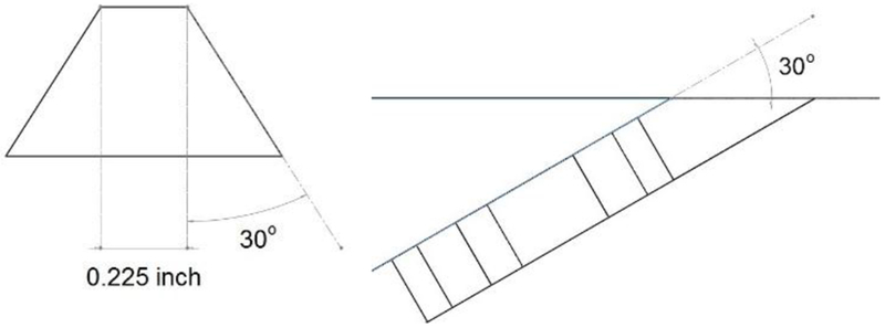
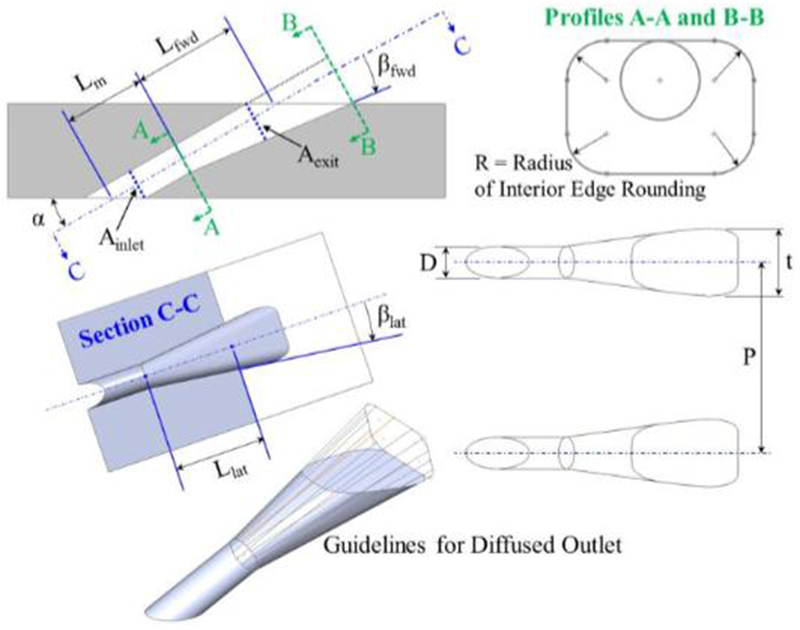
The fluidic actuator design, described earlier, had symmetrical passages in the internal geometry that allows the flow to oscillate between the passages depending on the pressure in each passage, and a square exit area of nominally 0.5 in2. It was not known beforehand how much spread angle the fluidic design would need, so a lateral angle of 30° and inclination angle of 0° was chosen for the exit, as shown in Figure 7. The flow inside the fluidic sweeping hole was studied using 3D unsteady RANS. A similar square exit flared hole without internal sweeping geometry was also tested. The “777” hole is a generic shaped hole [14], with the hole exit having lateral and inclination angles of 7° with the exit surface, as shown in Figure 8.
FIGURE 7.
GEOMETRY OF FLUIDIC AND SQUARE HOLES
FIGURE 8.
GEOMETRY OF 777 HOLE [14]
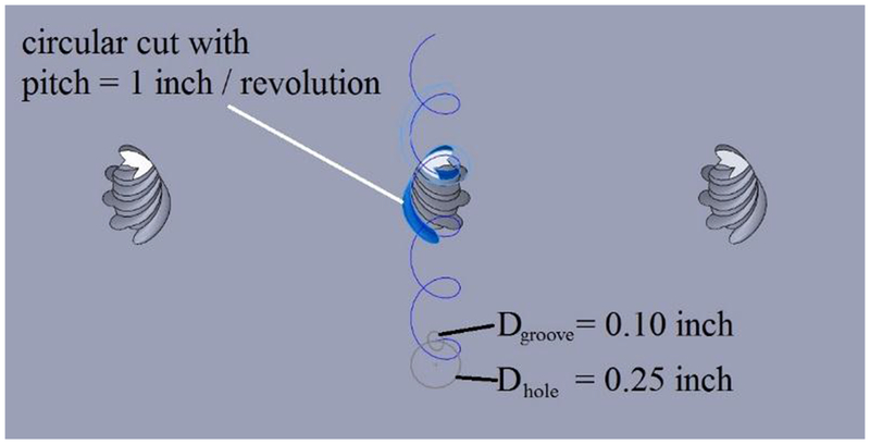
The spiral-grooved hole is a NASA patent-pending design; different groove thicknesses were tested, but the best results came from a large groove diameter of 0.1 inch with the groove center on the circumference of the main hole center and a rotating pitch of 1.0 inch, as shown in Figure 9. The main hole diameter was 0.25 inches and was inclined 30° from the horizontal. It was investigated whether the spiral groove needed to be cut through the entire length of the hole or just near the exit of the hole; the results showed that spiraling just the end of the hole provided minimal benefit and that the entire hole needed to be grooved to provide the most benefit. Two configurations of spiral holes were tested: one with the direction of the spiral alternating for each cooling hole, and another with the spirals in the same direction for each hole.
FIGURE 9.
GEOMETRY OF SPIRAL HOLES
The standard smooth round hole design also had a diameter of 0.25 inches and 30° from the horizontal. The compound angle design had smooth round holes at 30° from the horizontal and 30° from the streamwise direction.
For most of the constant cross sectional area hole shapes, the hole length L/D was 4, and the hole spacing P/D was 6. The architecture of the fluidic design, however, required a P/D of 6 and an L/D of 12. Thus the diffusion type hole shapes that were compared to the Fluidic hole used P/D of 6 and L/D of 12.
To compare the various film cooling shapes, film cooling effectiveness η was calculated from the infrared thermography images at different blowing ratios, BR, based on the following equations:
The coolant density was determined from the pressure taps and thermocouples located in the plenum. The coolant velocity was calculated from the mass flow rate through the hole (which is the flow rate into the plenum divided by the number of cooling holes) divided by the “metered” hole area (throat area of hole).
RESULTS
In the following sections, results from infrared thermography, hotwire surveys and thermocouple surveys are presented. Some results from CFD are also shown to provide an understanding of the flow within the fluidic hole. Further study is required to account for the effects of thermal conductivity in the upstream region of the cooling holes and this is beyond the scope of this paper. The results are broken up into two sections: the first dealing with the Fluidic hole and the second dealing with the Spiral hole.
Fluidic hole: comparison to 777 and Square holes
As mentioned earlier, the Fluidic hole is compared to the 777 hole and a Square hole. The Square hole has the same exit geometry of the fluidic hole but none of the internal geometry that produces the sweeping. Thus, it is a severely flared hole with a rectangular exit cross section. As such, it is expected to perform poorly because of the severe sweep angle of 30° to the centerline. The intent is to show the benefit of sweeping to diffusion type holes. It may be possible to increase diffusion, increase hole pitch to diameter ratio and thus to reduce the number of holes for a blade. The 777 hole is a standard diffusion type hole and is thus used in place of the customary circular hole.
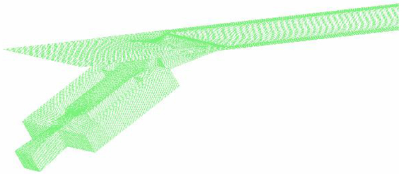
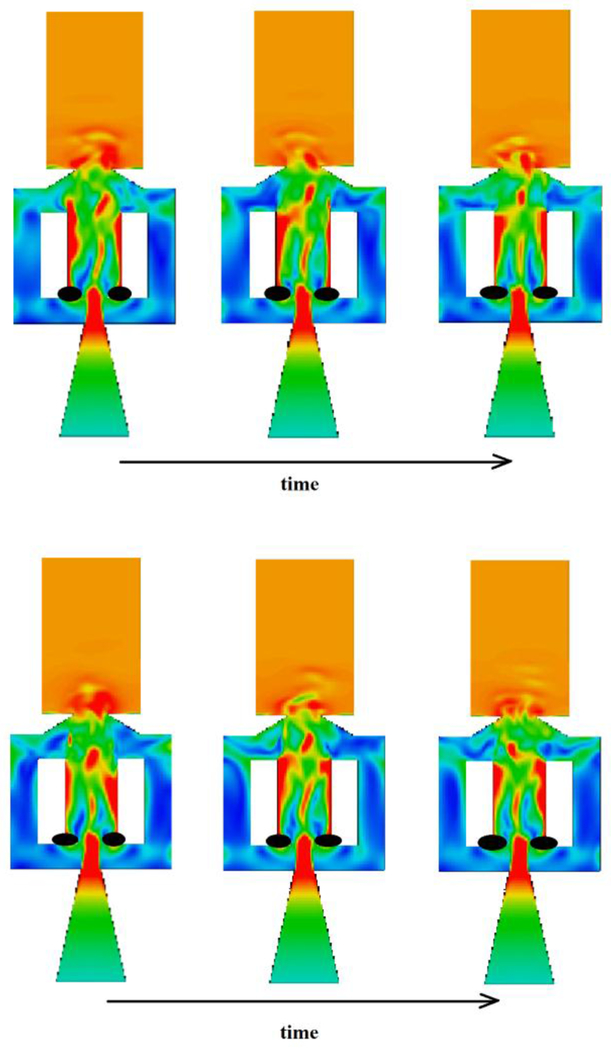
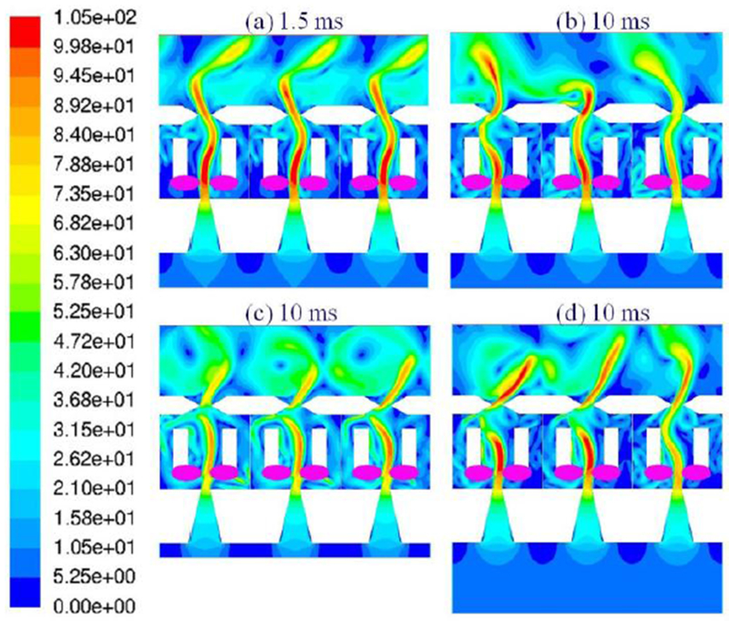
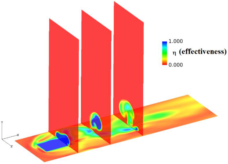
The 3D CFD tool Glenn-HT [15] was used to simulate the flow inside the fluidic actuator to qualitatively show the functioning of the fluidic holes. The mesh for the simulation was generated using GridPro and contained 424,000 points and is shown in Figure 10. Figure 11 shows snapshots of flow through the interior channels of the Fluidic hole as simulated by 3D CFD at a blowing ratio of 2.0. The images are colored by Mach number ranging from 0 (blue) to 0.45 (red). The highly unsteady nature of the device is evident. Notice that the jet is diffused at the hole exit and shows no kidney shaped vorticity in a time-averaged sense. The effect is similar to an increased level of freestream turbulence. Figure 12 shows a 2D Fluent calculation [16] of the fluidic jet without any crossflow at the exit. The shaded areas are to protect a proprietary design feature. The oscillating behavior of the jet is clearly illustrated in subsequent time steps. Figure 13 shows effectiveness contours at cross-sectional planes at x/d =2.0, 4.0 and 6.0 downstream of the hole exit showing the unsteady sweeping of the jet. Note the absence of a kidney-shaped vortex. The inner workings of fluidic devices are well known [11-13, 16] and we do not dwell on these details here. Rather, the focus is on the possible application of these devices for film cooling.
FIGURE 10.
CFD GRID FOR FLUIDIC HOLE
FIGURE 11.
SNAPSHOTS OF MACH NUMBER IN MID-PLANE OF FLUIDIC HOLE FROM UNSTEADY 3D CFD AT BR=2.0 (BLUE=0, RED=0.45)
FIGURE 12.
VELOCITY MAGNITUDE (M/S) SNAPSHOTS FROM UNSTEADY 2D CFD OF FLUIDIC HOLES WITHOUT CROSSFLOW AT EXIT: (A) SYNCHRONOUSLY STARTING AT 1.5 MS; (B) WELL-COUPLED PLENUM; (C) UNCOUPLED PLENUM; (D) WEAKLY-COUPLED PLENUM AT 10 MS [16]
FIGURE 13.
UNSTEADY SNAPSHOT OF EFFECTIVENESS CONTOURS FROM CFD AT BR=2.0
Infrared videos and snapshots were used to obtain the local adiabatic film effectiveness on the surface of the test articles as well as span-averaged effectiveness, centerline effectiveness and mid-pitch effectiveness. The span-averaged effectiveness is obtained by averaging a span of 1 pitch about the centerline of the central hole. The leading edge of the holes is nominally at x/D=0. The centerline effectiveness is the local adiabatic effectiveness along the centerline of the central hole. The mid-pitch line is an imaginary line that bisects any two hole centerlines.
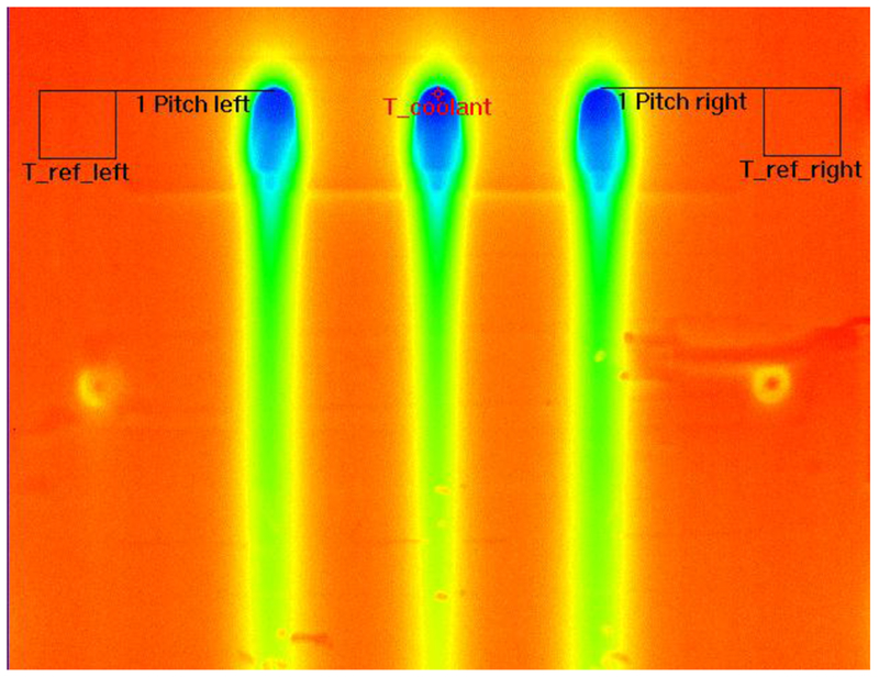
The method used to determine film effectiveness from infrared data is explained in detail in [3] but will be described here briefly. Figure 14 shows an example of a raw IR image (snapshot from a movie) that is yet to be processed. Regions of interest are labelled to show the locations at which the reference temperature and coolant temperature are measured. The adiabatic wall temperature Taw at each pixel location can be obtained from the infrared image directly. No adjustments are made for emissivity or transmission because in the temperature range being used and for the definition of effectiveness being employed, there is no difference in the effectiveness calculation using thermocouple ‘calibrated’ adiabatic wall temperatures and direct readings. Frames from the movie are first averaged over a period of 1s at a frame rate of 30Hz, with every 5th frame being stored, to yield a single infrared image. The coolant temperature Tc is obtained from this image near the center of the cooling hole and is a measure of the temperature on the wall on the cooling hole. The freestream recovery temperature TR∞ is obtained by averaging the values of temperature within the boxes labelled T_ref_left and T_ref_right. The boxes are located 1 pitch away from the nearest hole leading edge in the spanwise direction and contain 2592 pixels. The uncertainty in effectiveness, η, obtained using this method is within +/− 0.0025. Table 1 shows the temperatures used to calculate the effectiveness along with the uncertainties associated with each calculation.
FIGURE 14.
RAW INFRARED THERMOGRAPH SHOWING REGIONS OF INTEREST FOR EFFECTIVENESS COMPUTATION
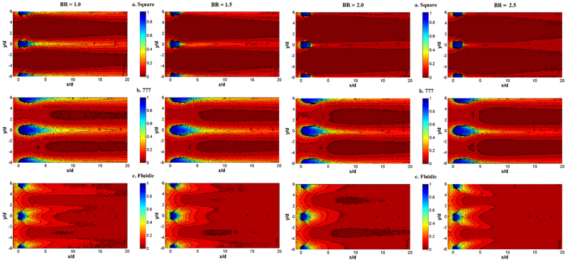
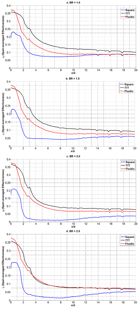
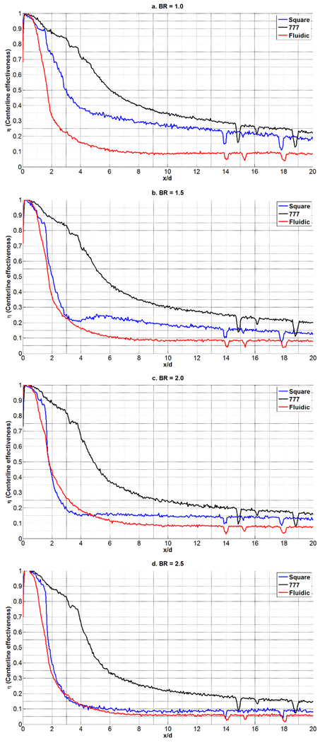
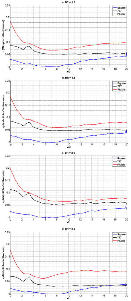
Figure 15 shows the adiabatic film effectiveness contours for the Square, 777, and Fluidic holes at blowing ratios from 1.0 to 2.5 (left to right). None of the holes show the characteristic pinching at high blowing ratio indicative of lift-off. Figure 16 shows the span-averaged film effectiveness about the center hole, and Figure 17 shows the centerline effectiveness. As the blowing ratio increases the 777 hole shows a drop in average effectiveness and at BR = 2.5, the 777 hole has the same average effectiveness as the Fluidic hole. Figure 17 shows that a large contribution to this averaged effectiveness is from the centerline effectiveness of the 777 hole. Note that the sharp spikes in Figures 16 and 17 for x/D>10 are a result of reflective paint location markers that were added to the tunnel floor. The Fluidic hole span-averaged effectiveness tends to hold as blowing ratio increases, matching the 777 effectiveness at BR = 2.5. It is curious that the Fluidic hole has the lowest effectiveness values at the centerline, but this is most likely due to the coolant sweeping near the hole reducing its concentration along the centerline. This low effectiveness at centerline, however, is offset by a higher effectiveness between the holes as seen in the mid-pitch effectiveness between the holes shown in Figure 18. Here it is evident that the Fluidic hole spreads the coolant and does not leave a concentrated streak downstream of the hole.
FIGURE 15.
ADIABATIC FILM EFFECTIVENESS BASED ON IR SURFACE TEMPERATURE MEASUREMENTS FOR SQUARE, 777 AND FLUIDIC HOLE AT DR=1.05. LEFT TO RIGHT: BR=1.0, 1.5, 2.0, 2.5
FIGURE 16.
SPAN-AVERAGED FILM EFFECTIVENESS FOR P/D=6.0, DR=1.05, FOR FLUIDIC, 777 AND SQUARE HOLES
FIGURE 17.
CENTERLINE EFFECTIVENESS FOR P/D=6.0, DR=1.05, FOR FLUIDIC, 777 AND SQUARE HOLES
FIGURE 18.
MID-PITCH EFFECTIVENESS FOR P/D=6.0, DR=1.05, FOR FLUIDIC, 777 AND SQUARE HOLES.
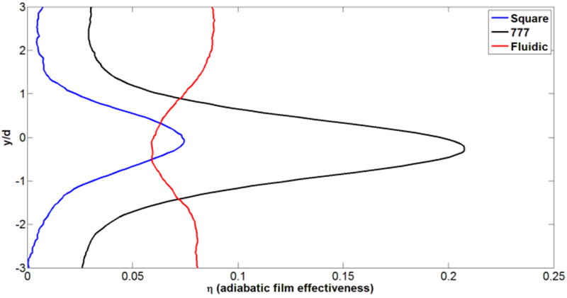
Overall, the Fluidic holes have a more uniform film coverage downstream of the holes. As an example, a spanwise plot of effectiveness at x/D=10.0 is shown in Figure 19. Another interesting fact is that the fluidic hole maintains effectiveness as blowing ratio increases and does not show lift-off characteristics. This is due to the sweeping of the coolant jet. Referring to Figure 3, one can see that the Fluidic hole operates in the regime where frequency is strongly dependent on the driving pressure of the hole. Thus, at high blowing ratios, the sweeping frequency increases, providing more uniform coverage. It may be possible to obtain higher effectiveness at lower blowing ratios by reducing the sweeping angle of the Fluidic hole, but such a parametric study is suggested for future work and is not dealt with here. Both the lateral angle of the shaped exit region, which was designed so as to not interfere with the jet, and the internal geometry of the fluidic design could be optimized to improve its performance.
FIGURE 19.
SPANWISE PLOTS OF ADIABATIC EFFECTIVENESS AT BR=2.5 AT X/D=10.
Spiral holes: comparison to cylindrical-type holes
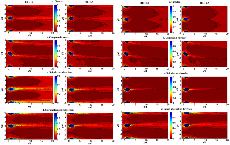
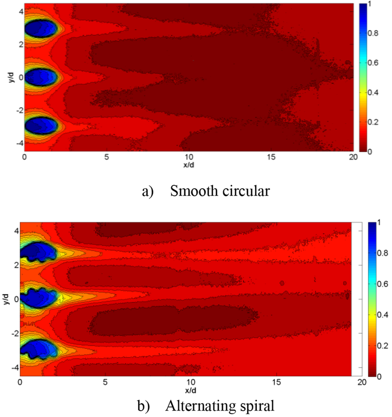
Figure 20 show the effectiveness values calculated from infrared measurements for cylindrical-type holes at P/D=6, with Table 2 showing the temperatures used to calculate the effectiveness. The spiral holes provide a different cooling pattern on the surface compared to smooth circular holes. The smooth holes at BR=2 show little surface cooling, as the jet has lifted off the surface. The compound angle hole also exhibits some lift off. The spiral hole, however, swirls the coolant to one side of the hole, and as can be seen in the image, the flow stays better attached to the surface. This swirling flow can be beneficial when a pair of holes spiral in opposite directions into each other, improving film coverage on the surface, or not as beneficial if the holes spiral away from each other.
FIGURE 20.
ADIABATIC FILM EFFECTIVENESS BASED ON IR SURFACE TEMPERATURE MEASUREMENTS FOR CYLINDRICAL-TYPE HOLES AT P/D=6.0, L/D=4.0, RE = 11,000. LEFT TO RIGHT: BR=1.0, 1.5, 2.0, 2.5
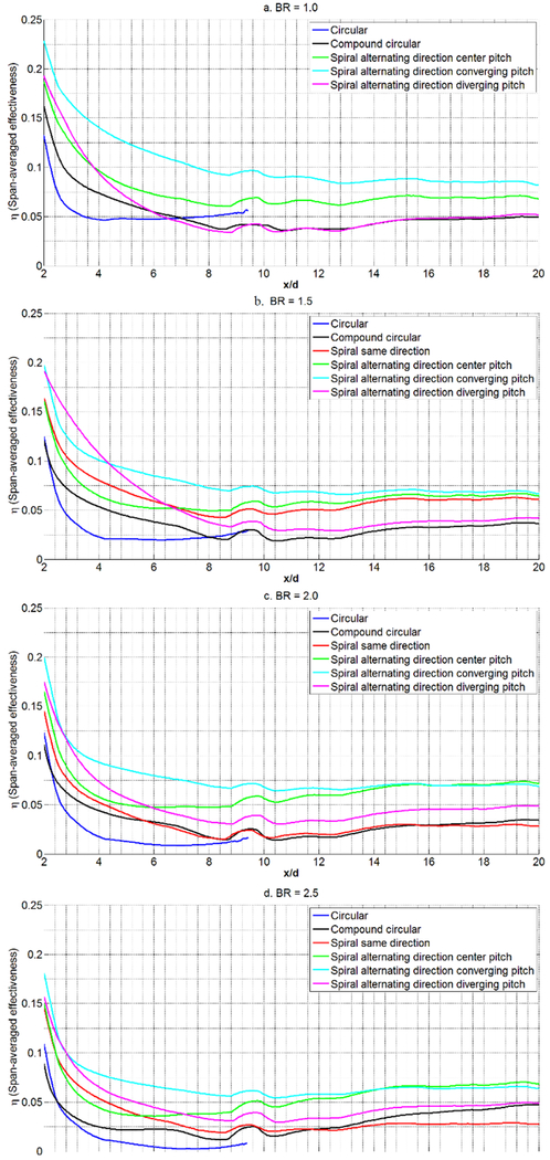
Figure 21 shows the span-averaged film effectiveness for the smooth circular, compound angle, and spiral holes. Alternating the direction of the spiral for each cooling hole produces better effectiveness. One can see the benefit of having a pair of converging spiral holes, which has the highest effectiveness values, whereas a pair of diverging spiral holes produces less benefit. If the spirals were in the same direction for all the cooling holes, the result is similar to smooth circular holes, especially at high blowing ratios. The bumps near x/D=9 is an artifact of tape that seals the interface between the insert and the tunnel floor.
FIGURE 21.
SPAN-AVERAGED FILM EFFECTIVENESS FOR P/D=6.0, DR=1.05, RE = 11,000 FOR CIRCULAR, COMPOUND ANGLE CIRCULAR, AND SPIRAL HOLES
The effect of swirling hole pairs is more pronounced if the hole spacing is reduced as seen in Figure 22. Here, BR=2, the pitch has been reduced to P/D=3, and the tunnel flow was limited to a Reynolds number of 7400. The results are similar to those with P/D=6, but the interaction between the pair of converging holes is much better downstream.
FIGURE 22.
FILM EFFECTIVENESS BASED ON IR SURFACE TEMPERATURE MEASUREMENTS FOR SMOOTH CIRCULAR AND SPIRAL HOLES AT P/D=3.0 AND BR=2.0
Flow and thermal field
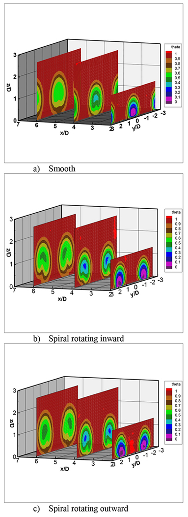
For temperature and flow field surveys, a larger hole size of 0.75 inch was used to better show flow features. Only smooth and spiral designs were investigated at this large scale. Figure 23 shows thermocouple survey measurements at BR=2 at different cross-sectional planes downstream of the film cooling holes using a non-dimensional temperature ratio defined as
For the smooth round hole case, a three-hole test piece was used with P/D=3. One can see the coolant jet liftoff and the kidney shaped vortex, which dissipates as the jet moves downstream. For the spiral holes, two separate two-hole test pieces was used, also with P/D=3. One test piece had the paired spiral holes facing each other, the other test piece had the paired spiral holes facing outward. The paired spiral holes at this large scale showed some coolant jet liftoff, different than what was seen using infrared thermography. Regardless, the kidney vortex has been replaced with swirling jets in opposite directions.
FIGURE 23.
THERMOCOUPLE SURVEY MEASUREMENTS
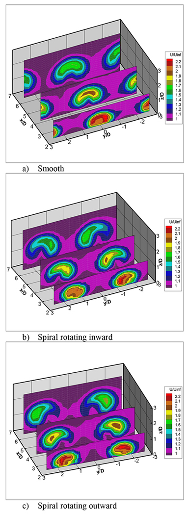
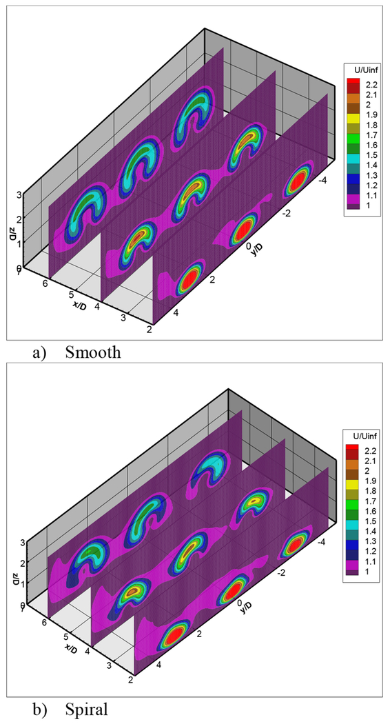
Hot-wire survey data at BR=2 and the same cross sectional planes as the thermocouple surveys are shown in Figure 24. Again, the kidney-shaped vortex is seen for the smooth hole as the coolant jet is lifted and separated. With the spiral hole, the swirl pattern is more pronounced, and as was seen in Figure 23, there is still some lift-off of the coolant jet, different than that seen from infrared thermography. One can see that if hole spacing was decreased, the interaction between the holes and thus the effectiveness would increase, especially for the spiral holes with flows swirling into each other.
FIGURE 24.
HOTWIRE SURVEY MEASUREMENTS
An opportunity arose to also provide particle image velocimetry data on the smooth and spiral hole shapes; these models had a hole diameter of 0.75 inch, P/D=3, and BR=2. A standard PIV cross-correlation was used to reduce the data. Figure 25 shows PIV data near the same cross section planes as in Figures 23 and 24. The differences between the two hole shapes is easily seen, with the spiral hole swirls dominant compared to the flow exiting the smooth hole. Again at this large scale, the spiral hole still shows some jet lift-off. These results are similar to the hot-wire data in Figure 24.
FIGURE 25.
PIV MEASUREMENTS
CONCLUSION
Infrared thermography, thermocouple surveys, hotwire surveys, and particle image velocimetry data were taken on two new film cooling hole geometries, one with spiral holes and the other with fluidic sweeping holes. Data was taken at a Reynolds number based on hole diameter and freestream velocity of 11,000 and with different hole spacing and blowing ratios. The spiral holes created vorticity to the flow exiting the hole and prevented the kidney shaped vortices associated with cylindrical-type film cooling jets. The patent-pending spiral hole design provided better film cooling effectiveness compared to smooth straight and compound angle cylindrical holes, especially at higher blowing ratios. Holes with spirals that alternated produced better effectiveness levels compared to holes with spirals in the same direction. The fluidic sweeping holes used a passive in-hole geometry to create a sweeping jet at frequencies that varied with blowing ratio. The Fluidic hole was compared with diffusion-type holes such as a generic shaped 777 hole and a square flared hole. The fluidic cooling hole showed lower centerline effectiveness levels but better uniform cooling flow distribution compared to the diffusion-type holes. An optimized design from smaller exit angles and modified internal geometry could produce better coolant effectiveness. Thermal, flow field, and particle image velocimetry data obtained for a larger scale version of the smooth cylindrical and spiraled holes verified the flow patterns associated with each type of hole, with the spiraled hole improving surface film effectiveness.
ACKNOWLEDGEMENTS
This work was funded by NASA’s Fundamental Aeronautics Program’s Fixed Wing Project and NASA’s Center Innovation Fund. The authors would also like to thank Dr. Mark Wemet and Dr. Adam Wroblewski for the particle image velocimetry results.
Contributor Information
Douglas Thurman, US Army Research Laboratory, Cleveland, OH, USA.
Dennis Culley, NASA Glenn Research Center, Cleveland, OH, USA.
Philip Poinsatte, NASA Glenn Research Center, Cleveland, OH, USA.
Surya Raghu, Advanced Fluidics LLC Columbia, Maryland, USA.
Ali Ameri, The Ohio State University Columbus, OH, USA.
Vikram Shyam, NASA Glenn Research Center, Cleveland, OH, USA.
REFERENCES
- [1].Bogard D, and Thole K, 2006, “Gas Turbine Film Cooling,” Journal of Propulsion and Power, 22(2), 249–270, DOI: 10.2514/1.18034. [DOI] [Google Scholar]
- [2].Bons JP, Rivir RB, Mac A, Charles D, “The Effect of High Freestream Turbulence on Film Cooling Effectiveness,” WL-TR-96-2097, 13–16 June 1994. [Google Scholar]
- [3].Shyam V, Thurman D, Poinsatte P, Ameri A, Eichele P, Knight J, “Long Hole Film Cooling Dataset for CFD Development, Part 1: Infrared Thermography and Thermocouple Surveys”, E-18773, NASA/TM-2013-218086. [Google Scholar]
- [4].Lutum E, and Johnson BV, 1998, “Influence of the Hole Length to Diameter Ratio on Film Cooling With Cylindrical Holes,” ASME J. Turbomachinery, 121, pp. 209–216. [Google Scholar]
- [5].Fric T, and Roshko A, 1994, “Vortical Structure in the Wake of a Transverse Jet”, Journal of Fluid Mechanics, Vol. 279, No. 1, pp. 1–47. [Google Scholar]
- [6].Thurman DR, E-Gabry LA, Poinsatte PE, Heidmann JD, 2011, “Turbulence and Heat Transfer Measurements in an Inclined Large Scale Film Cooling Array — Part I, ,” ASME paper GT2011-46498. [Google Scholar]
- [7].Thurman DR, E-Gabry LA, Poinsatte PE, Heidmann JD, 2011, “Turbulence and Heat Transfer Measurements in an Inclined Large Scale Film Cooling Array — Part II, Temperature and Heat Transfer Measurements,” ASME paper GT2011-46498. [Google Scholar]
- [8].Khajehhasani S, “Numerical Modeling Of Innovative Film Cooling Hole Schemes”, PhD Thesis, Ryerson University, Toronto, Ontario, Canada, 2014 [Google Scholar]
- [9].Bunker RS, 2005, “A Review of Shaped Hole Turbine Film Cooling Technology,” J. Heat Transfer, 127(4), pp. 441–453. [Google Scholar]
- [10].Colban Will F, Thole Karen A, Bogard David. A Film-Cooling Correlation for Shaped Holes on a Flat-Plate Surface J. Turbomach. 133(1), 011002 (2010) (11 pages); doi: 10.1115/1.4002064 [DOI] [Google Scholar]
- [11].Raghu S & Raman G (1999) Miniature fluidic devices for flow control. ASME FEDSM 99–7256. [Google Scholar]
- [12].Raghu S, “Feedback-free Fluidic Oscillator and Method,” U.S. Patent 6,253,782, issued July 3, 2001.
- [13].Raman G, Raghu S and Bencic TJ (1999) Cavity Resonance Suppression Using Miniature Fluidic Oscillators, AIAA-99-1900, 5th AIAA/CEAS Aeroacoustics Conference, Seattle, WA, May 10-12, 1999. [Google Scholar]
- [14].Schroeder R, Thole K, 2014, “Adiabatic Effectiveness Measurements For A Baseline Shaped Film Cooling Hole,” ASME paper GT2014–25992. [Google Scholar]
- [15].Steinthorsson E; Liou MS; and Povinelli LA: Development of an Explicit Multiblock/Multigrid Flow Solver for Viscous Flows in Complex Geometries. AIAA—93—2380 (NASA TM–106356), 1993. [Google Scholar]
- [16].Gokoglu S, Kuczmarski MA, Culley DE, and Raghu S, Poinsatte P., Thurman D, Shyam V., “Enhanced and Efficient Film Cooling of Turbine Blades using Fluidic Diverters”, NASA Center Innovation Fund Final Report, October 28th, 2011. [Google Scholar]


