Abstract
Purpose
To image the human trabecular meshwork (TM) in vivo using adaptive optics gonioscopy (AOG) with approximately 2-μm lateral resolution.
Methods
An existing Indiana University adaptive optics scanning laser ophthalmoscope was altered by adding a 12-mm button lens to a clinical gonioscopic lens allowing high-resolution imaging of the human iridocorneal angle. First an anatomic model eye was used to refine the imaging technique and then nine participants (7 controls and 2 participants with pigment dispersion syndrome) were imaged.
Results
All nine participants were successfully imaged without adverse events. High-resolution imaging of the human TM was achieved allowing for visualization of the TM beams, and presumed endothelial cells. Uveal meshwork beams in controls averaged 25.5 μm (range, 15.2–44.7) in diameter with pores averaging 42.6 μm (range, 22.3–51.4) while the corneoscleral meshwork pores averaged 8.9 μm (range, 7.7–12.1). Differences in appearance of the uveal and corneoscleral meshwork were noted between the two participants with pigment dispersion syndrome and the controls. These included nearly absent spacing between the beams and enlarged endothelial cells with hyperreflective areas.
Conclusions
AOG allows for near cellular level resolution of the human TM in vivo. This may allow for further understanding of age-related changes that occur as well as provide a deeper understanding of medical and surgical alterations for the treatment of glaucoma.
Translational Relevance
Further development of this approach may allow for direct measurements at a micometer level in vivo of changes that occur in the human trabecular meshwork with glaucoma and therapeutic interventions.
Keywords: adaptive optics, trabecular meshwork, glaucoma
Introduction
Glaucoma is defined as a progressive, characteristic optic neuropathy1 affecting approximately 64.3 million individuals worldwide.2 Glaucoma causes a loss of retinal ganglion cells, which leads to a characteristic visual field loss.3 The factors causing glaucoma include a continuum of factors ranging from biomechanics associated with intraocular pressure (IOP) to IOP-independent factors, including cerebrospinal fluid pressure and ocular hemodynamics.4 However, currently IOP is the only modifiable risk factor5 and management strategies aim to lower IOP through pharmaceutical or surgical approaches.
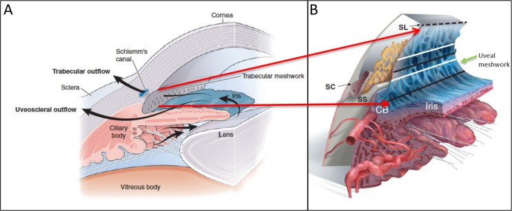
IOP is regulated by balancing aqueous humor inflow, from the ciliary epithelium, and outflow from the anterior segment. The conventional outflow pathway for aqueous humor is passage through the trabecular meshwork (TM) in the iridocorneal angle into Schlemm's canal and then through the collector channels to the episcleral veins.6 The TM occupies a small wedge-shaped area within the iridocorneal angle and can be divided into three sections with the most proximal (adjacent to the iris and anterior chamber), the uveal meshwork, a middle deeper portion, called the corneoscleral meshwork, and the deepest, the juxtacanalicular tissue adjacent to Schlemm's canal.7 The meshwork is composed of a series of sheets of collagenous beams covered with mesenchymally derived endothelial cells.8–10 The deeper uveal meshwork and corneoscleral meshwork trabeculae flatten and run parallel to the limbus11 creating a meshwork of progressively smaller pores through which the aqueous humor flows. This filter-like structure (Fig. 1) is thought to be a major source of outflow resistance along the conventional outflow pathway, and thus damage here can increase IOP.
Figure 1.
Schematic of normal aqueous pathway of the iridocorneal angle. (A) Normal aqueous pathway from the ciliary body moving past the lens and through the pupil into the TM. (B) Enlarged cross-sectional schematic of the iridocorneal angle providing more detail of the iridocorneal angle with Schlemn's canal (SC), scleral spur (SS), ciliary body (CB), and Schwalbe's line (SL). The area between the dashed line and the upper white line indicates the anterior portion of the TM. The upper black line indicates the posterior TM (Post. TM) overlying SC. The lower white line indicates the area of the TM above the SS while the lower black line corresponds with TM over CB and represents the CB band (CBB) in clinical imaging. The uveal meshwork (green arrow) is anterior to the corneal scleral meshwork (not shown). Images reprinted with permission from Freddo TF, Chaum, E. Anatomy of the Eye and Orbit. 1st ed. Philadelphia, PA: Wolters Kluwer; 2017.
Current clinical imaging of the TM is limited in resolution, and thus clinical judgements are constrained to evaluating basic landmarks. The most anterior landmark of the TM is Schwalbe's line (the termination of corneal endothelium). Then viewing posteriorly, the anterior meshwork is nonpigmented while the more posterior meshwork overlying Schlemm's canal is pigmented. The scleral spur, the posterior of the landmark of the TM, will often be seen and more posteriorly still, the ciliary body band (CBB; Fig. 2).
Figure 2.

Clinical slit-lamp gonioscopy image (16× magnification) demonstrating SL, the anterior TM (Ant. TM), Post. TM, and the CBB. Note that with clinical examination of the anterior chamber angle, the structures are only seen as bands demarcated by pigmentation and no fine anatomic structure is evident.
The resolution limitations of current techniques arise from the anatomy of the eye with the TM lying at the apex of the iridocorneal angle. Light cannot be used to directly image the TM through the cornea because under normal conditions light reflected from the angle structures undergoes total internal reflection at the tear-air interface. Thus, a lens and mirror combination, in direct contact with the cornea, a gonioscopic or gonio lens, is used to view the TM using a slit lamp, and the resulting view is low resolution. Attempts to view the TM using anterior-segment optical coherence tomography (OCT) have provided some details of the TM,12–14 but only image the gross structure of the TM and Schlemm's canal. While OCT has been applied in a gonioscopy approach15,16 the lateral resolution is similar to clinical imaging with added depth information. Additionally, two-photon and multiphoton imaging of the TM17–21 has provided in situ and ex vivo information of these structures and can help discriminate them, but has not been used in humans in vivo. Yet, TM imaging that provides micrometer-level resolution would aid in understanding the aging changes which likely cause the elevated incidence of glaucoma with age, allow evaluation of those glaucoma medications22 which have their impact at the level of the TM, as well as improve the outcome evaluation and failure modes of surgical modalities, such as the various minimally invasive glaucoma surgery (MIGS) procedures.23
In the current proof of concept paper, we present a high-resolution, adaptive optics scanning laser ophthalmoscope (AOSLO) imaging system, originally designed for retinal imaging,24–26 coupled with a custom modified gonioscopic lens and patient interface. We present the details of the new lens attachment and initial data with optical lateral resolution on the order of 2 μm, obtained from imaging the human TM in vivo.
Methods
Modified AOSLO for Imaging the Iridocorneal Angle In Vivo
The Indiana University AOSLO has been previously described.25,26 Briefly, this portion of the system acquires raster scanned images in both confocal and multiply scattered light imaging modes at a frame rate of approximately 28 Hz. Adaptive optics control is maintained using a Shack-Hartmann wavefront sensor operating at 880 nm and two deformable mirrors.27 Two imaging channels were used simultaneously, operating at 785 and 820 nm. Following each imaging session individual frames were corrected for sinusoidal distortion resulting from resonant galvanometer-driven scanning. The corrected individual frames were then processed to automatically determine an acceptable template frame and to align each frame to the template, removing the impact of the small residual eye movements and pulsations.28
Gonioscopic Lens and Optics
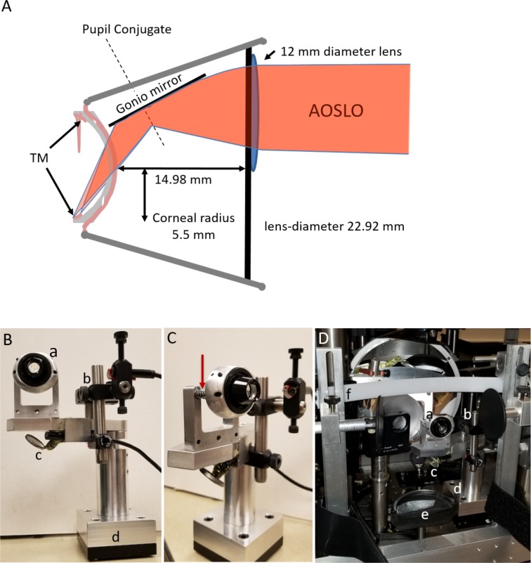
A specially modified gonio lens was mounted into the system. This lens was made by affixing a 12-mm button lens to the anterior surface of a clinical single-mirrored gonio lens (OSMG; Ocular Instruments Inc., Bellevue, WA). The button lens was centered over the mirror location. This button lens was chosen to provide optical correction for infinity at the approximate distance of the angle structures in order to allow the imaging system to operate near its emmetropic correction. The gonio lens was placed in optical contact with the anterior surface of the cornea to avoid the total internal reflection that otherwise prevents imaging the iridocorneal angle. To facilitate steering of our imaging beam we configured the positioning of the gonio lens such that the pupil of the adaptive optics gonioscopy (AOG) system, which was optically conjugate to the steering mirrors, was located on the internal mirror of the gonio lens. This causes a slight minification of the pupil, but allows us to change the angle of regard of the imaging system over a considerable range of angles while maintaining the pupil on the mirror of the gonio lens. A schematic of our final design is shown in Figure 3.
Figure 3.
Optical schematic and setup of the AOG gonioscopic lens system. (A) AOSLO rays are converged by the convex button lens applied to the surface of the clinical gonio lens. Light then reflects off the gonio mirror, through the concave back surface of the gonio lens, a layer of Goniosoft, and the cornea to the iris insertion. The TM is anterior to this location at a steep angle. Light rays from the AOSLO are drawn twice with different convergences to show that focusing must be done by the operator as one image along the TM from posterior to anterior. (B) Participant's view of the gonio attachment. (a) Gonio lens with button lens visible on the AOSLO side. (b) Borescope camera focused on the lens eye interface to monitor vertical alignment. (c) Borescope camera imaging the eye gonio lens interface from below off a mirror to monitor horizontal alignment. (d) Kinematic base allowing the gonio attachment to be precisely replaced on the participant's end of the AOSLO. (C) Side view of the spring mounts (red arrow) on the gonio lens allowing for small anterior/posterior movements of the participant's eye without breaking contact. (D) The gonio attachment mounted to the AO system. (a–d) Same as in Panel B, (e) chin rest, and (f) forehead rest.
Lens Mount and Patient Interface
For clinical use, a gonioscopic lens is held in contact with the cornea by the clinician. The clinician then moves both the slit lamp and the lens on the patient's cornea to obtain the desired view of the TM. This flexibility is required due to the large individual differences in the size and shape of the anterior segment of the eye. Because the exit pupil of the AOG is fixed, the gonioscopic lens needs to be fixed relative to the imaging system and the patient needs to be moved to the gonioscopic lens. Light pressure of the lens on the eye is needed to maintain optical contact with the gonio lens. To meet these requirements, we designed a custom gonio lens mount and placed it on a magnetic kinematic plate, such that the whole assembly could be moved in and out of the AOG reproducibly, allowing use of the AO system for either retinal or TM imaging (Fig. 3).
The model eye or the patient's eye was moved into optical contact with the gonio lens using a motorized chin and forehead rest with three degrees of freedom. The chin rest included adjustable temple pads and a Velcro (Velcro, London, UK) strap to hold the head steady during imaging. Goniosoft (OCuSOFT, Richmond, TX) was used to cover the cornea and the corneal surface of the gonio lens, allowing full optical contact between the eye and lens. To ensure that the lens remained in contact with the cornea, the gonio lens was mounted to the mechanical stage using two springs operating in compression. Thus, the eye could move forward or backward while maintaining contact with the gonio lens without excessive pressure on the eye (Fig. 3).
Model Eye Imaging
For initial testing and calibration, we used an anatomically realistic gonio-model eye developed to train surgeons on selective laser trabeculoplasty (SimulEye; InsEYEt, LLC Westlake Village CA). This model eye was mounted in place of the chin rest.
To obtain model eye images Goniosoft was placed on both the artificial cornea and on the curved surface of the gonio lens. The model eye was advanced using the motorized positioner until Goniosoft could be seen to sweep over the interface between the lens and cornea on the image from the axial video camera. Both confocal and multiply scattered light images were taken either simultaneously or sequentially. Multiply scattered light images were obtained by displacing the aperture of one of the imaging channels.29,30 We inserted short segments of precision wire with diameters of 200 μm (The Crazy Wire Company, Warrington, UK) into the gonio-model eye and used images uploaded into Adobe Photoshop CC 2017 18.0.1(San Jose, CA) to determine an imaging scale.
Position Monitoring
To avoid corneal injury and ensure good optical contact between the cornea and the lens, a real-time monitoring system was used to observe the eye and head of the patient. Six video cameras were used simultaneously and displayed on a computer monitor during patient positioning and imaging. The first camera, located just above the imaging beam and looking along the beam, allowed visualization of the spreading of the Goniosoft as the patient was brought into contact with the gonio lens. Two cameras were mounted on the gonio lens mechanical mount for close visualization of the gonio lens–cornea conjugation. Three additional cameras were positioned to allow visualization of the head position of the human participants because it is critical that the head be in a chin-forward approach in order to achieve an even mating of the cornea with the gonio lens surface.
Imaging of the Human Iridocorneal Angle
The study protocol was approved by Indiana University institutional review board and adhered to the Declaration of Helsinki. Nine participants, seven control participants (ages 29–68) and two participants with pigment dispersion syndrome (PDS; ages 26 and 31), had the inferior angle of their right eye imaged after obtaining informed consent (Table 1). As this was a proof of concept study, we elected to first just image the inferior angle though a rotation of the gonio lens would allow imaging of the superior, temporal, or nasal angle.
Table 1.
AOG Iridocorneal Angle Structures Visualized in Each Participant
| Subject |
Age |
Sex |
Race |
Post. TM |
Ant. TM |
SL |
Corneal Collagen |
Other |
| 1 | 66 | Male | Caucasian | No | Yes | Yes | Yes | Plateau Iris |
| 2 | 29 | Male | Asian | Yes | Yes | No | No | |
| 3 | 45 | Female | Caucasian | Yes | Yes | Yes | Yes | |
| 4 | 26 | Female | Caucasian | Yes | Yes | Yes | Yes | |
| 5 | 30 | Female | Caucasian | Yes | Yes | Yes | No | |
| 6 | 31 | Male | Caucasian | Yes | Yes | Yes | Yes | PDS |
| 7 | 68 | Male | Caucasian | Yes | Yes | Yes | Yes | |
| 8 | 26 | Female | Caucasian | No | Yes | No | No | PDS |
| 9 | 55 | Female | Caucasian | No | Yes | No | No |
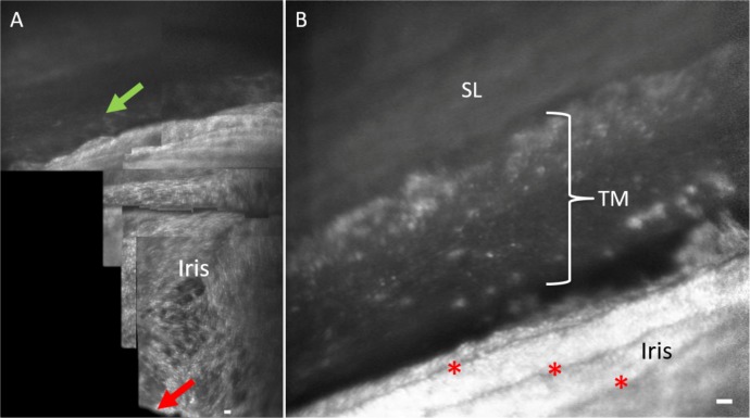
The seven control participants had normal IOPs, no history of glaucoma or intraocular surgery, and were not taking any ocular medications. The two participants with pigment dispersion syndrome had normal IOPs and have not been diagnosed with glaucoma. Prior to the AOG imaging session, clinical gonioscopy and gonio photography at 16× were performed on all participants to document anatomical landmarks and the depth of the iridocorneal angle. The AOG beam power was measured before participants were imaged at all visits to ensure we were well below the American National Standards Institute Z136 for laser safety (which is based on the retina). The AOG is typically operating at 150 μW. In comparison, diode laser trabeculoplasty at a similar wavelength typically averages a power of 1100 mW.31 Prior to imaging each human participant, the model eye was imaged first as a check of the system. Each participant was topically anesthetized using an ophthalmic preparation of tetracaine and an adjustable closed-bladed lid speculum was placed in the right eye to make sure the eyelids were clear of the gonio lens. Goniosoft was applied to the cornea as well as the posterior surface of the gonio lens. The patient was then secured in the head rest and a Velcro strap was fastened behind the head. Each participant was moved into contact with the gonio lens and imaged. Imaging was performed by first focusing on the anterior iris plane and then steering the imaging beam into the iridocorneal angle (Fig. 4).
Figure 4.
Orientation to iridocorneal angle structures with AOG imaging. (A) Initial imaging of human participants start by visualizing the iris plane and pupil margin (red arrow) and then advancing into the iridocorneal angle. The posterior uveal meshwork (green arrow) is visible at the junction of the iris into the angle of subject 3. (B) More magnified view of the iridocorneal angle in participant 2. Iris folds are visible (red asterisks) leading into the angle structures. Scale bars, 50 μm.
At each location 50 video frames were acquired. The scan was then steered to adjacent regions with approximately 50% overlap between video grabs. Images were acquired with 2.6° × 2.4°, 2.0° × 1.8°, or 1.33° × 1.2° field sizes. The lateral resolution was roughly 0.4 arc min, or 2 μm, although due to the variation in the size of the cornea and the depth of the iridocorneal angle, this will vary across participants. For a diffraction limited system, the axial resolution is approximately 60 μm, although the actual depth of field depends on the anterior segment anatomy and quality of the wavefront correction. Each imaging session lasted 10 to 20 minutes. After the imaging session, participants were backed out of the gonio lens, the lid speculum was removed and the participants were taken to an examination room to have the Goniosoft rinsed out of their eye and the integrity of the corneal surface examined with slit-lamp biomicroscopy. The best images from the gathered video sequences per participant were imported into Adobe Photoshop CC after processing in order to measure the structural characteristics of the TM beams and cells.
Results
All nine participants were successfully imaged using AOG. The imaging procedure was well-tolerated, with no corneal epithelial defects noted on slit-lamp exam following the imaging session. We were able to image from the pupil margin of the iris radially out to the iridocorneal angle in all participants. However, as in clinical imaging, the variability in the shape of the anterior segment caused the extent of visible TM to vary (Table 1). For instance, in one participant it was difficult to image the TM because of a plateau iris configuration, blocking visualization of the posterior iridocorneal angle. The imaging session allowed us to scan the inferior angle in a sweeping motion and to reliably visualize the same structures with each pass. Additionally, four of nine participants elected to return for a second imaging session at another date. This confirmed the same structures were reliably and repeatably imaged.
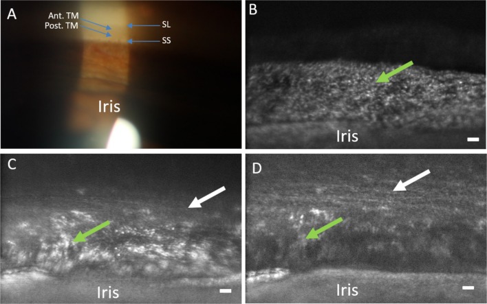
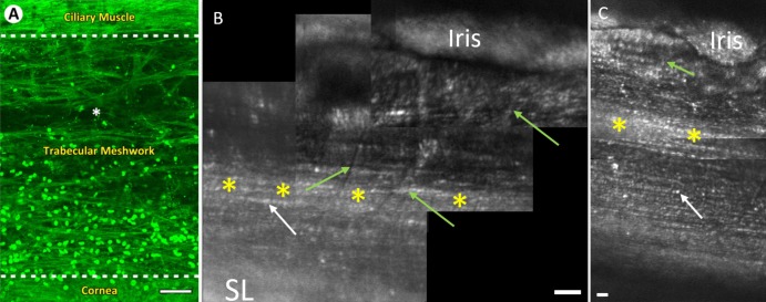
The system provided clear images of the iris stroma, processes, and crypts (Fig. 5), as well as visible blood flow in iris vessels. Comparing standard clinical gonio photography with AOG images, greater detail was seen with AOG including details of the proximal uveal meshwork and underlying corneoscleral meshwork (Fig. 6). The uveal TM was seen as a superficial loose meshwork directly overlying the deeper tightly packed beams of the corneoscleral meshwork (Figs. 6, 7). In the anterior portion of the uveal trabecular meshwork we could easily adjust focus to visualize regularly spaced corneoscleral TM beams oriented parallel to the limbus (Figs. 7, 8). These beams appear beaded presumably with endothelial cell somas on the meshwork beams. Anterior to the beams we could see Schwalbe's line and even the thicker corneal collagen bundles. Extensions of the uveal meshwork are perpendicular to Schwalbe's line and overlie the more densely packed striated beams. The posterior uveal meshwork appears to vary widely in appearance between individuals with more densely packed TM beams compared with the anterior TM (Figs. 7, 8). There were individual differences in the appearance and number of uveal meshwork beams coursing from their posterior insertion anterior toward Schwalbe's line and the three-dimensional nature of the TM required careful focus. Figure 6 illustrates the change in appearance of the TM with increasing focal depth in the same region of TM, starting with the initial focus on the proximal uveal TM (Fig. 6B) and then progressing deeper into the more organized striated beams (Fig. 6D). A more reflective line was consistently visible midway between the iris and Schwalbe's line as the montages in Figures 7 and 8 illustrate.
Figure 5.
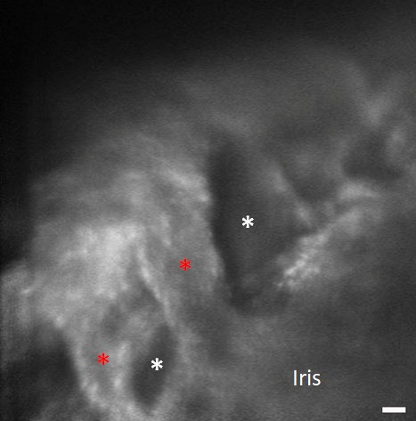
Detailed image of the iris in participant 7. Thick iris strands (red asterisks) and iris crypts (white asterisks) are visible. Scale bar, 50 μm.
Figure 6.
Comparison of clinical gonioscopic and AOG images in participant 3. (A) Clinical view of iridocorneal angle through a gonioscopic lens (16× magnification). (B) The posterior uveal meshwork is in focus (green arrow) with the iris at the bottom of the image. (C) The focus is transitioning through the uveal meshwork (green arrow) to the deeper corneoscleral meshwork (white arrow). (D) Focus has shifted to the corneoscleral meshwork (white arrow) while part of the uveal meshwork (green arrow) and iris can still be seen. Note the level of detail in comparison to the clinical image. Scale bars, 50 μm.
Figure 7.
Views of the TM with clinical and AOG imaging in participant 4. (A) An enlarged region of the slit-lamp image showing SL, the Ant. TM, the Post. TM, and the CBB. (B) AOG image of the same region in the same participant obtained with an intermediate AOG magnification. (C) Image acquired of the same region as (B), but now at the maximum magnification of the AOG imaging system focusing on the Post. TM. Here, we can resolve both the uveal beams (green arrows) and the deeper corneoscleral beams (white arrows). Scale bar, 50 μm.
Figure 8.
Views of the TM with two-photon and AOG imaging. Note, images are inverted compared with prior figures. (A) En face autofluorescence section of the human TM in situ using two-photon imaging (reprinted by permission from Gonzalez JM Jr, Heur M, Tan JC. Two-photon immunofluorescence characterization of the trabecular meshwork in situ. Invest Ophthalmol Vis Sci. 2012;53:3395–404). The CBB is seen as dense horizontal fibers at the top of the image. TM beams are seen between the hash lines with loosely packed beams near the ciliary muscle and densely packed beams below. The cornea is seen below the bottom hash line. Hoechst-33342 labeling illustrates the TM cell nuclei. (B) AOG montage of iridocorneal angle in participant 4. The uveal meshwork beams (green arrows) are visualized coursing vertically over deeper, more densely packed corneoscleral TM beams (white arrow) running parallel to the limbus. (C) AOG montage of iridocorneal angle in participant 5. In both participants, a reflective band of the TM is visible midway up the iridocorneal angle (yellow asterisks). The densely packed corneoscleral TM beams (white arrows) are visible in both participants. In both participants densely packed corneoscleral TM beams (white arrows) run parallel to the limbus and become thinner as we move anteriorly. The beaded appearance of cellular bodies on the beams in AOG images (B, C) closely resembles that of the cell nuclei on the TM beams in panel A. Scale bars, 50 μm.
In all controls with high-quality images of the TM, measurements were taken from the best quality image per participant by one of the authors (BJK). In each case 10 separate structures (e.g. corneoscleral beam width) were measured three times and then averaged over all measurements within a participant. The diameter of the presumed endothelial cell somas ranged from 5.9 to 7.7 μm (Table 2). Uveal meshwork beams in controls averaged 25.5 μm (range, 15.2–44.7) The measured separation of the TM beams (pores) varied significantly between participants. Despite the variation, the more anterior TM structures are parallel striated beams compared with the more randomly oriented posterior beams and the deeper corneoscleral beams were more densely spaced compared to the uveal meshwork beams (average corneoscleral 8.9 μm; average uveal 42.6 μm) in all participants. We did find that pores between uveal meshwork beams ranged from 22 to 51 μm, and for the spacing between beams of the corneoscleral meshwork, we found a range of 7.7 to 12.1 μm. In four controls, we were able to image anteriorly past Schwalbe's line, and in those participants, we visualized presumed corneal collagen bundles. In two controls, we were able to image perpendicular to the cornea and see corneal endothelial cells (Participants 1 and 7).
Table 2.
Participants in Which Resolution Allowed Measuring for All the Reported TM Structures With Age, Averages, and Standard Deviationa
| Subject |
Age |
UM Beam Average, μm |
UM Pore Average, μm |
CS Pore Average, μm |
TM cell Size Average, μm |
| 3 | 45 | 15.9 (±4.7) | 22.3 (±6.1) | 8.2 (±1.8) | 6.6 (±1.6) |
| 4 | 26 | 15.2 (±4.0) | 38.57 (±17.8) | 7.9 (±1.1) | 5.9 (±1.3) |
| 5 | 30 | 26.2 (±8.4) | 51.4 (±18.4) | 7.7 (±2.3) | 6.7 (±2.0) |
| 7 | 68 | 44.7 (±17.9) | 48.5 (±25.4) | 12.1 (±3.5) | 7.7 (±1.9) |
| Total Avg. | 25.5 (±15.6) | 42.6 (±19.6) | 8.9 (±2.9) | 6.7 (±1.8) |
UM, uveal meshwork; CS, corneoscleral.
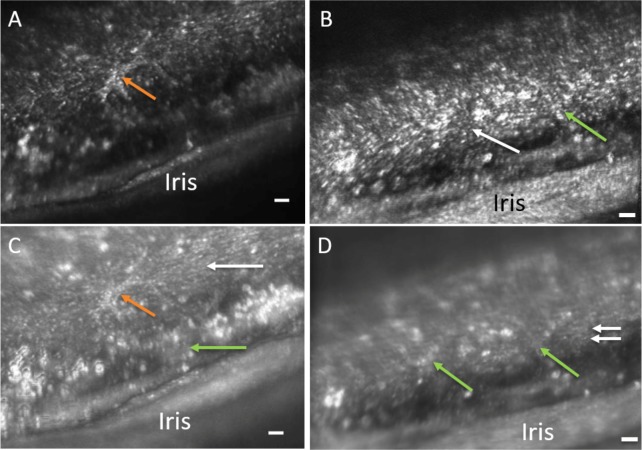
In comparing the two participants with pigment dispersion syndrome to the seven controls, the highly pigmented structures appear intensely bright with plaque-like areas within the TM. Large pigment granules or presumed pigment engorged TM endothelial cells were visible in both participants and there was no visible separation between TM beams (Fig. 9) preventing beam diameter measurements. Additionally, a bright cell-like structure is visible with possible pseudopod arms presumed to be a macrophage with engulfed pigment granules.
Figure 9.
Confocal (A, B) and multiply scattered (C, D) AOG images of a participant with pigment dispersion syndrome. Intensely bright areas of presumed pigmented granules are visible throughout the images. Panels A and C show a cell-like structure with pseudopod arms (orange arrows). Both uveal meshwork (green arrows) and corneoscleral meshwork are also visible in the multiply scattered light image (Panel C). Panels B and D show the overlying uveal meshwork (green arrows) slightly out of focus and deeper corneoscleral meshwork (white arrows). Note that in the multiply scattered image (Panel D), further structural detail is evident of the TM. “Y” shaped patterns of uveal meshwork beams (green arrows) are evident traversing over the deeper corneoscleral meshwork beams that run horizontally (white arrows). The spaces between the corneoscleral beams appear narrow in comparison to the other participants. Scale bars, 50 μm.
Discussion
We used a new adaptive optics gonioscopy system to successfully image each of nine participants, two of whom had pigment dispersion syndrome at a micrometer scale in vivo. Clinical gonioscopy and gonio photography largely show only the degree to which the angle is open, the amount of pigmentation, and anatomic features such as iris processes. Comparison of the AOG images to clinical gonio photography of the same participant shows anatomic correspondence between features, such as visible iris processes, but with much greater detail in AOG. The highly pigmented angles of the PDS participants illustrate abundant highly refractive areas within cells presumed to be melanin granules. Specifically, many features are visible with AOG that are not resolved with clinical gonioscopy. The beams of the TM are seen and the beaded appearance of the beams may indicate TM endothelial cell somas especially when comparing with in situ two-photon immunoflourescence20 (Fig. 8). The uveal meshwork is fairly irregular in structure and overlies a system of regular limbal parallel beaded beams demonstrated in the control participants.
Uveal extensions perpendicular to Schwalbe's line are quite prominent in our AOG imaging similar to extensions that have been visualized by scanning electron microscopy (SEM)8,10 as well as ex vivo and in situ two-photon and multiphoton imaging.17–21 The appearance of the more anterior TM beams on AOG differ somewhat from that on SEM imaging.8 The TM beams seen by SEM appear more as a randomly structured meshwork, whereas the AOG images demonstrate a more regular banded or striated appearance (Fig. 8). This striated appearance is comparable to images from recent two-photon and multiphoton ex vivo imaging.20,21 The difference may arise from the fixation processing required for the SEM imaging and also from our direct en face imaging of the TM adjacent to the aqueous. In the anterior portion of the TM, limbal parallel striations become more apparent. Less of the overlying irregular uveal meshwork as one image anteriorly may increase visibility of the underlying more regular corneoscleral TM. The measurements of distance between striated appearing TM beams is consistent with what has been reported in two-photon and multiphoton imaging for the corneoscleral meshwork.20,21 We found for the spacing between beams of the corneoscleral meshwork a range of 7.7 to 12.1 μm and the literature reports values from histology of 2 to 15 μm and our measurements on the spacing between uveal meshwork beams ranged from 22 to 51 μm with literature reports of 25 to 75 μm.32 Thus, our pilot measurements are consistent with the histologic literature. The scleral spur, which is visible in clinical examination, is not as apparent in our images, as it is deep to the TM and in our AOG contrast is dependent on backscattering, which emphasizes surface as opposed to deeper structures. We do however see a bright band in most participants in the appropriate position. It is not yet clear whether this band is the underlying scleral spur or due to backscattering from melanin granules lodged in the meshwork directly overlying Schlemm's canal, usually an area of greater pigmentation.
The separation between beams observed in controls was not readily visualized in participants with PDS (see also Ref. 33). This suggests that the TM endothelial cells on the surface of the beams are engorged with pigment granules. The areas of high reflectivity seen within the TM endothelial cells are consistent with internalized melanin granules. Previous light microscopy and SEM images from participants with PDS indicate that the majority of the pigment granules found in these layers of the TM to be within swollen endothelial cells.33,34 Additionally, there appeared to be an occasional cell visualized with a macrophage-like appearance (Figs. 9A, 9C). Histologically, macrophages have been shown to be present in the TM assisting the TM endothelial cells with phagocytosis.7 Additionally, extensive loss of TM cells and collapsed or fused TM lamellae have been noted histopathologically in participants with pigmentary glaucoma.33,35
A threshold level of the TM endothelial cells seems essential for the normal maintenance and function of the TM lamellae because denuded beams lead to a collapse of the TM structure with fusion of the beams.34,36 TM endothelial cells number declines with aging,37 which may be a reason for decreased outflow and increased incidence of glaucoma in the aging population.
The TM endothelial cells cover the beams with thin cytoplasmic extensions, which would not be visualizable but assessing the number of cell somas present would be a quantification that could be of great prognostic import. If this is the case, subject cell counts in aging adults and patients with glaucoma may allow predictions of clinical course in progressive open-angle glaucoma, the most common form. Pharmaceutical agents used in the treatment of open-angle glaucoma that work largely at the level of the conventional outflow pathway yet very little data are available on the consequences of their use on the structure of the TM. A common surgical intervention in glaucoma is the use of laser trabeculoplasty. Dynamic consequences to the TM structure from this procedure still remain unclear. Another apparent application of AOG would be in the analysis of the changes occurring over time after placement of MIGS devices as they often lower pressure for a year or two and then seem to fail. Possibly the healing response around the device leads to its failure or improper initial anatomic placement but current clinical gonioscopic imaging has insufficient resolution to assess these problems. We suggest that all current glaucoma interventions acting on the conventional drainage pathway would benefit from the improved imaging provided by AOG, which resolves both the trabecular beams and the TM endothelial cells.
Limitations
The current modified AOSLO has several limitations when applied to TM imaging. First, it is designed for retinal imaging, and thus the pupil is fixed in space. Clinically, the gonioscopic lens is rotated and tilted by the clinician to access the entire TM if needed. In our case, the eye and lens are fixed within an imaging session. This restricts our current imaging system to approximately 30° in the inferior angle though if the lens rotational position was altered, any other portion of the angle could have been observed. A movable pupil in the AOSLO coupled with a mechanically rotated gonio lens would allow full 360° imaging of the angle in a single session. Last, imaging with a longer wavelength may provide for deeper inspection into the TM potentially allowing for visualization of the juxtacanalicular tissue, the structure adjacent to Schlemm's canal.
Summary
AOG imaging of the TM provides micrometer level imaging in vivo in humans. The images obtained show the beams and endothelial cells of the TM and are comparable to images obtained with two-photon imaging in nonclinical contexts. This proof of concept investigation is encouraging for continued progress on a specifically developed AOG system to provide imaging of the detailed anatomic structure of the TM and how this relates to the development of elevated IOP, the primary driver of glaucoma. Further development of this technology may also elucidate the mechanisms of pharmacologic treatments and surgical alterations to outflow of aqueous humor in patients with glaucoma. In this regard, we may be able to identify reasons for success or eventual failure of pharmaceutical, laser, and surgical interventions.
Acknowledgments
The authors would like to thank Thomas Freddo, OD, PhD for his help with Figure 1 and opinions on the trabecular meshwork, Stuart Stoll, MD with insEYEt LLC for his help with the SimulEye, and Peter Harrington with Ocular Instruments, Inc. for his assistance with constructing the gonioscopic lens.
Supported by National Institutes of Health Grant R01-EY024315 (SAB) and American Academy of Optometry Foundation: Allergan Foundation Research Grant (SAB).
Disclosure: B.J. King, None; S.A. Burns, None; K.A. Sapoznik, None; T. Luo, None; and T.J. Gast, None
References
- 1.Foster PJ, Buhrmann R, Quigley HA, Johnson GJ. The definition and classification of glaucoma in prevalence surveys. Br J Ophthalmol. 2002;86:238–242. doi: 10.1136/bjo.86.2.238. [DOI] [PMC free article] [PubMed] [Google Scholar]
- 2.Tham YC, Li X, Wong TY, Quigley HA, Aung T, Cheng CY. Global prevalence of glaucoma and projections of glaucoma burden through 2040: a systematic review and meta-analysis. Ophthalmology. 2014;121:2081–2090. doi: 10.1016/j.ophtha.2014.05.013. [DOI] [PubMed] [Google Scholar]
- 3.Kerrigan-Baumrind LA, Quigley HA, Pease ME, Kerrigan DF, Mitchell RS. Number of ganglion cells in glaucoma eyes compared with threshold visual field tests in the same persons. Invest Ophthalmol Vis Sci. 2000;41:741–748. [PubMed] [Google Scholar]
- 4.Shields MB. Normal-tension glaucoma: is it different from primary open-angle glaucoma? Curr Opin Ophthalmol. 2008;19:85–88. doi: 10.1097/ICU.0b013e3282f3919b. [DOI] [PubMed] [Google Scholar]
- 5.Anderson DR. for the Normal Tension Glaucoma Study. Collaborative normal tension glaucoma study. Curr Opin Ophthalmol. 2003;14:86–90. doi: 10.1097/00055735-200304000-00006. [DOI] [PubMed] [Google Scholar]
- 6.Civan MM, Macknight AD. The ins and outs of aqueous humour secretion. Exp Eye Res. 2004;78:625–631. doi: 10.1016/j.exer.2003.09.021. [DOI] [PubMed] [Google Scholar]
- 7.Stamer WD, Clark AF. The many faces of the trabecular meshwork cell. Exp Eye Res. 2017;158:112–123. doi: 10.1016/j.exer.2016.07.009. [DOI] [PMC free article] [PubMed] [Google Scholar]
- 8.Hansson HA, Jerndal T. Scanning electron microscopic studies on the development of the iridocorneal angle in human eyes. Invest Ophthalmol. 1971;10:252–265. [PubMed] [Google Scholar]
- 9.Gierek A, Sosnierz M, Bialas B, Szymanski A. Morphological picture of the iridocorneal angle of the human eyeball viewed under a scanning electron microscope. Ophthalmologica. 1974;169:371–376. doi: 10.1159/000307139. [DOI] [PubMed] [Google Scholar]
- 10.Abu-Hassan DW, Acott TS, Kelley MJ. The trabecular meshwork: a basic review of form and function. J Ocul Biol. 2014. 2. [DOI] [PMC free article] [PubMed]
- 11.Gong H, Tripathi RC, Tripathi BJ. Morphology of the aqueous outflow pathway. Microsc Res Tech. 1996;33:336–367. doi: 10.1002/(SICI)1097-0029(19960301)33:4<336::AID-JEMT4>3.0.CO;2-N. [DOI] [PubMed] [Google Scholar]
- 12.Wang D, Lin S. New developments in anterior segment optical coherence tomography for glaucoma. Curr Opin Ophthalmol. 2016;27:111–117. doi: 10.1097/ICU.0000000000000243. [DOI] [PubMed] [Google Scholar]
- 13.Crowell EL, Baker L, Chuang AZ, et al. Characterizing anterior segment OCT angle landmarks of the trabecular meshwork complex. Ophthalmology. 2018;125:994–1002. doi: 10.1016/j.ophtha.2018.01.018. [DOI] [PubMed] [Google Scholar]
- 14.Fernandez-Vigo JI, Garcia-Feijoo J, Martinez-de-la-Casa JM, Garcia-Bella J, Fernandez-Vigo JA. Morphometry of the trabecular meshwork in vivo in a healthy population using fourier-domain optical coherence tomography. Invest Ophthalmol Vis Sci. 2015;56:1782–1788. doi: 10.1167/iovs.14-16154. [DOI] [PubMed] [Google Scholar]
- 15.McNabb RP, Challa P, Kuo AN, Izatt JA. Complete 360 degrees circumferential gonioscopic optical coherence tomography imaging of the iridocorneal angle. Biomed Opt Express. 2015;6:1376–1391. doi: 10.1364/BOE.6.001376. [DOI] [PMC free article] [PubMed] [Google Scholar]
- 16.Perinchery SM, Shinde A, Fu CY, et al. High resolution iridocorneal angle imaging system by axicon lens assisted gonioscopy. Sci Rep. 2016;6:30844. doi: 10.1038/srep30844. [DOI] [PMC free article] [PubMed] [Google Scholar]
- 17.Ammar DA, Lei TC, Masihzadeh O, Gibson EA, Kahook MY. Trans-scleral imaging of the human trabecular meshwork by two-photon microscopy. Mol Vis. 2011;17:583–590. [PMC free article] [PubMed] [Google Scholar]
- 18.Masihzadeh O, Ammar DA, Kahook MY, Gibson EA, Lei TC. Direct trabecular meshwork imaging in porcine eyes through multiphoton gonioscopy. J Biomed Opt. 2013;18:036009. doi: 10.1117/1.JBO.18.3.036009. [DOI] [PMC free article] [PubMed] [Google Scholar]
- 19.Gonzalez JM, Jr, Ammar MJ, Ko MK, Tan JC. Optimizing two-photon multiple fluorophore imaging of the human trabecular meshwork. Mol Vis. 2016;22:203–212. [PMC free article] [PubMed] [Google Scholar]
- 20.Gonzalez JM, Jr, Heur M, Tan JC. Two-photon immunofluorescence characterization of the trabecular meshwork in situ. Invest Ophthalmol Vis Sci. 2012;53:3395–404. doi: 10.1167/iovs.11-8570. [DOI] [PMC free article] [PubMed] [Google Scholar]
- 21.Gonzalez JM, Ko MK, Pouw A, Tan JC. Tissue-based multiphoton analysis of actomyosin and structural responses in human trabecular meshwork. Sci Rep. 2016;6:21315. doi: 10.1038/srep21315. [DOI] [PMC free article] [PubMed] [Google Scholar]
- 22.Lin CW, Sherman B, Moore LA, et al. Discovery and preclinical development of netarsudil, a novel ocular hypotensive agent for the treatment of glaucoma. J Ocul Pharmacol Ther. 2018;34:40–51. doi: 10.1089/jop.2017.0023. [DOI] [PMC free article] [PubMed] [Google Scholar]
- 23.Dang Y, Wang C, Shah P, et al. Outflow enhancement by three different ab interno trabeculectomy procedures in a porcine anterior segment model. Graefes Arch Clin Exp Ophthalmol. 2018;256:1305–1312. doi: 10.1007/s00417-018-3990-0. [DOI] [PMC free article] [PubMed] [Google Scholar]
- 24.Burns SA, Tumbar R, Elsner AE, Ferguson D, Hammer DX. Large-field-of-view, modular, stabilized, adaptive-optics-based scanning laser ophthalmoscope. J Opt Soc Am A Opt Image Sci Vis. 2007;24:1313–1326. doi: 10.1364/josaa.24.001313. [DOI] [PMC free article] [PubMed] [Google Scholar]
- 25.Ferguson RD, Zhong Z, Hammer DX, et al. Adaptive optics scanning laser ophthalmoscope with integrated wide-field retinal imaging and tracking. J Opt Soc Am A Opt Image Sci Vis. 2010;27:A265–A277. doi: 10.1364/JOSAA.27.00A265. [DOI] [PMC free article] [PubMed] [Google Scholar]
- 26.Burns SA, Elsner AE, Chui TY, et al. In vivo adaptive optics microvascular imaging in diabetic patients without clinically severe diabetic retinopathy. Biomed Opt Express. 2014;5:961–974. doi: 10.1364/BOE.5.000961. [DOI] [PMC free article] [PubMed] [Google Scholar]
- 27.Zou W, Qi X, Burns SA. Wavefront-aberration sorting and correction for a dual-deformable-mirror adaptive-optics system. Opt Lett. 2008;33:2602–2604. doi: 10.1364/ol.33.002602. [DOI] [PMC free article] [PubMed] [Google Scholar]
- 28.Huang G, Zhong Z, Zou W, Burns SA. Lucky averaging: quality improvement of adaptive optics scanning laser ophthalmoscope images. Opt Lett. 2011;36:3786–788. doi: 10.1364/OL.36.003786. [DOI] [PMC free article] [PubMed] [Google Scholar]
- 29.Elsner A, Miura M, Burns S, et al. Multiply scattered light tomography and confocal imaging: detecting neovascularization in age-related macular degeneration. Opt Express. 2000;7:95–106. doi: 10.1364/oe.7.000095. [DOI] [PubMed] [Google Scholar]
- 30.Chui TY, Vannasdale DA, Burns SA. The use of forward scatter to improve retinal vascular imaging with an adaptive optics scanning laser ophthalmoscope. Biomed Opt Express. 2012;3:2537–2549. doi: 10.1364/BOE.3.002537. [DOI] [PMC free article] [PubMed] [Google Scholar]
- 31.Farrar SK, Roberts C, Johnston WM, Weber PA. Optical properties of human trabecular meshwork in the visible and near-infrared region. Lasers Surg Med. 1999;25:348–362. doi: 10.1002/(sici)1096-9101(1999)25:4<348::aid-lsm9>3.0.co;2-2. [DOI] [PubMed] [Google Scholar]
- 32.Freddo TF, Chaum E. Anatomy of the Eye and Orbit 1st ed. Philadelphia, PA: Wolters Kluwer; 2017. [Google Scholar]
- 33.Shimizu T, Hara K, Futa R. Fine structure of trabecular meshwork and iris in pigmentary glaucoma. Albrecht Von Graefes Arch Klin Exp Ophthalmol. 1981;215:171–180. doi: 10.1007/BF00413148. [DOI] [PubMed] [Google Scholar]
- 34.Richardson TM, Hutchinson BT, Grant WM. The outflow tract in pigmentary glaucoma: a light and electron microscopic study. Arch Ophthalmol. 1977;95:1015–1025. doi: 10.1001/archopht.1977.04450060101010. [DOI] [PubMed] [Google Scholar]
- 35.Murphy CG, Johnson M, Alvarado JA. Juxtacanalicular tissue in pigmentary and primary open angle glaucoma. The hydrodynamic role of pigment and other constituents. Arch Ophthalmol. 1992;110:1779–1785. doi: 10.1001/archopht.1992.01080240119043. [DOI] [PubMed] [Google Scholar]
- 36.Grierson I, Wang Q, McMenamin PG, Lee WR. The effects of age and antiglaucomatous drugs on the meshwork cell population. Res Clin Forums. 1982. 69.
- 37.Alvarado J, Murphy C, Juster R. Trabecular meshwork cellularity in primary open-angle glaucoma and nonglaucomatous normals. Ophthalmology. 1984;91:564–579. doi: 10.1016/s0161-6420(84)34248-8. [DOI] [PubMed] [Google Scholar]


