

Abstract
The existence of a third visual area, V3, along the outer margin of V2 was originally proposed for primates on the basis of projections from V1. The evidence for V3 was never totally convincing because investigators failed to demonstrate V1 projections to ventral V3, and projections to dorsal V3 could be attributed to the dorsomedial visual area (DM). We have reexamined the issue by placing large injections into both dorsal and ventral portions of V1 and subsequently processing flattened cortex for myelin and cytochrome oxidase so that borders of V1 and V2 could be determined accurately. The injections were in small-brained marmosets, where ventral V1 was most accessible and cortex could be flattened easily. The results indicate that dorsal V1 (representing the lower visual quadrant) projects to a narrow “dorsal V3” located between DM and dorsal V2, whereas ventral V1 (representing the upper visual quadrant) projects to a narrow “ventral V3.” Architectonic borders for these dorsal and ventral strips were clearly apparent. In addition, all parts of V1 project to DM, whereas ventral V1 connections indicate that the dorsolateral area (DL) extends more ventral than has been established previously. We also placed injections within dorsal V2, dorsal and ventral DM, and dorsal, central, and ventral middle temporal (MT) area. Results from these injections were consistent with the proposed retinotopic organizations of V3, DM, and DL. We provide compelling evidence for the existence of areas V3, DM, and DL in marmosets and suggest that these areas are likely to be found in all primates.
Keywords: V3, DM, DL, V4, MT, visual cortex, extrastriate cortex
Despite >30 years of intensive research on the organization of visual cortex in primates, there is widespread agreement on the existence of only a few visual areas (Kaas, 1996, 1997). Surprisingly, V3 or VIII, one of the first proposed extrastriate visual areas in primates, has been one of the most questioned. The first evidence for a V3 came from studies of the projection patterns of V1 in macaque monkeys (Cragg, 1969; Zeki, 1969). V1 appeared to project topographically to two successive belt-like surrounding fields, an immediately adjacent V2 and a V3 along the outer border of V2. The proposed areas were continuous and approximately equal in width, and they formed mirror images of each other in retinotopic organization. The concepts of V2 and V3 fit well with expectations stemming from the early cytoarchitectonic descriptions ofBrodmann (1909) of a large primary visual cortex, area 17, surrounded by areas 18 and 19, especially because areas 18 and 19 had already been associated with a V2 and a V3 in cats (Hubel and Wiesel, 1965). In fact, V2 and V3 were originally designated as “areas 18 and 19” in macaques (Zeki, 1969) despite the recognition that the V1 projection fields were both well within Brodmann's proposed area 18.
Although evidence accumulated for the existence of V2, and V2 is now a widely accepted subdivision of visual cortex, convincing evidence for V3 failed to materialize. The first problem was that V3 did not correspond to any of Brodmann's architectonic subdivisions, and subsequent architectonic attempts to define the field were inconsistent and unconvincing (see Discussion). A second problem was that further studies of V1 projections in primates did not reveal a complete ring-like projection field along the outer border of V2. Projections to cortex just rostral to V2 either were not found in squirrel monkeys (Spatz and Tigges, 1972) or were found only in a small region of cortex along the dorsomedial (DM) rostral border of V2. These V1 projections to a dorsomedial location were interpreted either as within another visual area, DM, in owl monkeys (Lin et al., 1982;Krubitzer and Kaas, 1993) or to a dorsal V3 that differed considerably from the V3 of initial proposals in macaque monkeys (Burkhalter et al., 1986; Van Essen et al., 1986). Some held that V3 existed only along the dorsomedial border of V2, rather than as a long, band-like area. This dorsal V3 was a fragment of its former size, and it had the improbable characteristic of representing only the lower visual quadrant. Other types of evidence, from microelectrode mapping studies, investigations of single neuron response properties, and imaging brain activity, have not resolved the issue, and a range of opinions continues to persist (see Discussion).
Because of the importance of the issue, we reinvestigated the connections and architecture of the V3 region. The results provide evidence for a modified V3, DM, and an enlarged dorsolateral (DL) visual area [Stepniewska and Kaas (1996); for the relationships of DM to V3A and DL to V4 of macaque monkeys, see Beck and Kaas (1999)].
MATERIALS AND METHODS
We related cortical patterns of cytochrome oxidase (CO) and myelin to connections of V3 and DM after multiple injections of fluorescent and bi-directional tracers into retinotopic locations in V1, V2, DM, and middle temporal (MT) areas in a total of nine marmosets (Callithrix jacchus) (see Table 1). Of particular interest was whether ventral V1 interconnects with ventral cortex lateral to V2. Because it is difficult to inject all parts of V1 and flatten cortex in macaques, we used the more manageable brains of New World marmoset monkeys. The small, liscencephalic brain of the marmoset enabled us to more easily place large injections of tracers in ventral V1 and more effectively flatten cortex so that areal patterns in the architecture and connections could be evaluated. In addition to V1 injections, we placed injections within V2, MT, and the proposed field DM to help determine further whether V3 and DM are valid areas. Marmosets also served as a useful model because of the existence of detailed retinotopic maps of the areas that we injected (Rosa and Schmid, 1995; Fritsches and Rosa, 1996; Rosa et al., 1997; Rosa and Elston, 1998; Rosa and Tweedale, 2000). Therefore we were able to infer retinotopy from our connection patterns.
Table 1.
Summary of injection sites
| Case number | Injection site | Tracer | Figure |
|---|---|---|---|
| 99-64 | Ventral V1 | CTB | 7B |
| DY | 7C | ||
| FB | 1B,7A | ||
| Dorsal V1 | FR | 7D | |
| 99-51 | Dorsal V2 | CTB | N.S. |
| FB | 8A | ||
| FR | 8B | ||
| Ventral DM | DY | 9 | |
| 99-48 | Ventral V1 | CTB | 5 |
| FE | 6 | ||
| FR | 6 | ||
| Dorsal V1 | DY | 6 | |
| FB | 6 | ||
| 99-21 | Dorsal MT | FR | N.S. |
| 98-6 | Dorsal DM | DY | N.S. |
| Central MT | FE | N.S. | |
| 98-4 | Dorsal DM | FB | 10B |
| Ventral MT | DY | 10B | |
| 97-141 | Dorsal V2 | FB | N.S. |
| 97-123 | Dorsal DM | FB | 10A |
| Ventral MT | DY | 10A | |
| 97-109 | Dorsal V2 | DY | N.S. |
Injection site indicates whether a tracer was placed in the dorsal or ventral aspect of the listed visual area. DY, Diamidino yellow; FB, Fast Blue; FE, fluoroemerald; FR, fluororuby; N.S., not shown.
Surgery and injections. All procedures were approved by the Vanderbilt animal care and use committee and followed National Institutes of Health guidelines. Marmosets were anesthetized with ketamine hydrochloride (30 mg/kg) and xylazine (5 mg/kg) and placed in a stereotaxic headholder, and different portions of the dorsolateral surface of visual cortex were exposed depending on the intended injection sites (see below).
For V1 injections, a small portion of the skull covering the caudal end of visual cortex in the left hemisphere was removed by trephination and small rongeurs. After removal of the dura, portions of the dorsal lateral surface, the medial wall, and ventral surface of striate cortex were gently aspirated away to allow access to the calcarine sulcus of the right hemisphere (Fig.1A). Once the dura was removed from the medial wall of the right hemisphere the calcarine sulcus was clearly visible (Fig. 1B). We were able to inject a total of nine neuroanatomical tracers (see below) in two cases along the upper and lower banks of the calcarine sulcus (see Results) without contamination of the opposite hemisphere. Pressure injections of 0.1–0.3 μl were made at ∼20° from perpendicular to the cortical surface using a stereotaxic syringe holder and 1.0 μl Hamilton syringes with sealed glass micropipettes. Any leakage of tracer from the injection site was removed with a swab during and after the injection to prevent any artifactual spread. Injections placed on the lower bank were considered to be in the upper quadrant of V1, whereas injections along the upper bank were considered to be in the lower quadrant (Fig.2B) [based on retinotopic maps of marmoset V1 by Fritsches and Rosa (1996)]. Injections were placed by estimated depth into the middle layer of cortex. The dense core of injected tracer included both supragranular and infragranular layers in all instances. After injections, gel foam was used to replace the aspirated cortex, and the opening of the skull was sealed with a thin cap of dental acrylic.
Fig. 1.
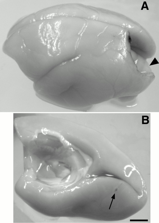
A, A dorsolateral view of a marmoset brain. A caudal portion of the left cortical hemisphere was removed by aspiration to allow access to the calcarine sulcus of the right hemisphere. As opposed to larger New World monkeys and prosimian galagos, the cerebellum (arrowhead) does not occlude the calcarine sulcus, so that injections could be placed on both its upper and lower banks. B, View of the medial and ventral walls of the right cortical hemisphere. The arrow indicates an FB injection (case 99-64) placed well ventral to the calcarine sulcus near the V1/V2 border in the peripheral upper quadrant of V1 (see Results). By removing the corresponding cortex of the left hemisphere (A), we were able to inject both upper and lower quadrants of V1 directly, without having to penetrate through dorsolateral cortex of the same hemisphere with possible tracer leakage to nontargeted regions of cortex. Left is rostral;up is dorsal. Scale bar, 4 mm.
Fig. 2.

A, Our current proposal for how visual cortex is subdivided into areas in New World marmosets. More established areas are outlined, others are indicated byabbreviations, and other proposed areas are not included. Outlined areas include primary visual cortex (V1), the second visual area (V2), dorsal and ventral divisions of a redefined third visual area, V3 (V3d and V3v), the dorsomedial area (DM), the middle temporal area (MT), the middle temporal crescent (MTc), the medial superior temporal area (MST), and the dorsal and ventral divisions of the fundal area of the superior temporal sulcus (FSTdand FSTv). Borders for the caudal and rostral (DLc and DLr) divisions of the dorsolateral area (DL) are defined primarily by connection patterns and not architecture; therefore dashed lines are used. Representations of the upper (+) and lower (−) visual quadrants are indicated for some of the visual areas. Also, for some visual areas the zero horizontal (hollow circles) and the zero vertical (hollow squares) meridians are marked. Filled circles represent estimated location of foveal vision in V1, V2, DM, and MT. The locations of the dorsointermediate area (DI), caudal inferior temporal area (ITc), superior temporal sulcus (STS), and posterior parietal (PP) visual regions, the ventral parietal (VPP), and the lateral parietal (LPP) are also indicated. For reference the somatosensory areas, area 3b or primary somatosensory cortex (S1), somatosensory areas 1 and 3a, the second somatosensory area (S2), the parietal ventral somatosensory area (PV), and the auditory core (A) are also outlined. LS, Lateral sulcus. The two asterisks and the adjoiningarc indicate adjacent points of cortex (as indicated by the thin black lines) before cutting the lip of the upper bank of the calcarine sulcus to permit the unfolding of the medial and ventral walls. White-tipped arrows designate the caudal (1) and rostral (2) ends of the lower bank of the calcarine sulcus. Shading indicates cortex that was exposed by unfolding. B, A view of the medial and ventral surface of marmoset cortex before unfolding. The peripheral border of V1 is indicated, with the lower quadrant (−) of V1 on the upper bank of the calcarine sulcus and the upper quadrant (+) located on the lower bank of the calcarine. Cortex within the calcarine sulcus is designated by dark gray. The thick white line indicates where cortex was cut along the lip of the upper bank of the calcarine. CC, Corpus callosum.Black arrows in both A andB indicate medial (M) and rostral (R) directions.
For V2, DM, and MT injections, a larger portion of the dorsal lateral cortical surface was exposed so that at least one-third of the lateral sulcus, the tip of the superior temporal sulcus, the lip of the medial wall, and the dense vessel pattern of striate cortex were visible after removal of the dura. All injections were made perpendicular to the cortical surface. Injections in dorsal MT were made by placing the micropipette ∼3–4 mm caudal from the tip of the lateral sulcus. Injections in central and ventral MT were placed between 3 and 6 mm lateral to the dorsal MT injections. Coordinates for marmoset MT injections were based on the retinotopic maps of Rosa and Elston (1998)and the position of MT seen in myelin stains (Lyon et al., 1998). DM was injected by first placing the micropipette ∼7–8 mm caudal to the tip of the lateral sulcus. For injections placed in dorsal DM, the tip of the micropipette was then moved medially to the lip of the medial wall. For the injection placed in ventral DM, the needle tip was next moved laterally ∼5–6 mm. Coordinates for DM injection sites were based on myelin patterns seen in preliminary work (Lyon et al., 1998), injections in other New World monkeys (Krubitzer and Kaas, 1990a, 1993;Beck and Kaas, 1998), and microelectrode maps of dorsomedial marmoset cortex (Rosa and Schmid, 1995). V2 injections were placed ∼2–4 mm caudal to the DM injections and up to 5 mm lateral from the medial lip. After injections, a soft disposable contact lens was used to cover the defect in the dura, and the skull opening was covered with a thin cap of dental acrylic. Then the scalp was sutured, and the closed incision was treated with antibiotic ointment. Each marmoset was then given prophylactic injections of penicillin (60,000 U/kg) and an analgesic, banamine (1 mg/kg). They were carefully monitored during recovery from anesthesia.
Tracers used in this study included 0.1–0.3 μl of fluorochromes diamidino yellow (DY; 2%) (Keizer et al., 1983), Fast Blue (FB; 3%) (Kuypers et al., 1980), fluororuby (FR; 10%) (Schmued et al., 1990), and fluoroemerald (FE; 10%) (Novikova et al., 1997) and the bi-directional tracer, cholera toxin-B subunit (CTB; 5%) (Ericson and Blomqvist, 1988).
Histology and data analysis. Seven to nine days after surgery, the marmosets were first anesthetized with ketamine hydrochloride (30 mg/kg) and xylazine (5 mg/kg) and then a lethal dose of sodium pentobarbital. When areflexive, they were perfused transcardially with 0.9% PBS followed by a solution of 2% paraformaldehyde fixative and subsequently 2% paraformaldehyde with 10% sucrose in PBS.
After removal of the brain, the cortical hemispheres were carefully separated from underlying structures and subsequently flattened in one of two ways. All flattening was similar to previous methods used for marmosets (Krubitzer and Kaas, 1990b, 1993) but differed in how the calcarine sulcus was unfolded. We focused on either maintaining the opened calcarine sulcus in one piece (Fig. 2A) or cutting it through the middle (along the fundus of the calcarine), presumably separating upper and lower quadrants of V1 into equal halves. After they were flattened, the hemispheres were submerged overnight in 30% sucrose in PBS while placed under a glass slide. Additional weight was not placed on top of the glass slide because the relatively liscencephalic marmoset cortex was easy to flatten.
The next day, the flattened hemispheres were frozen and cut parallel to the surface in 40 μm sections. A series of every third or fourth section was mounted on glass slides without further processing to observe fluorescent tracers. If CTB was injected, a second series was put through an immunocytochemical procedure to visualize the transported label (Bruce and Grofova, 1992; Sakai et al., 2000). Two more series were processed for either myelin (Gallyas, 1979) or CO (Wong-Riley, 1979).
The location of retrogradely labeled fluorescent and CTB cells and anterogradely labeled terminals were digitized by using an XY encoder attached to the stage of a high-powered fluorescent and bright-field microscope and plotted with the aid of Igor Pro (WaveMetrics, Lake Oswego, OR). The XY coordinates were imported as EPS files from Igor Pro into Canvas 7 (Deneba) and printed. Borders from CO and myelin stains of adjacent sections were drawn on printed copies of each cortical section with plotted cells, scanned into Canvas 7, and redrawn digitally. Within Canvas 7, labeled cells were aligned with adjacent sections using injection sites, blood vessel patterns, and section contours as landmarks.
The image in Figure 1 was captured using a digital camera (Scion Corp.) and NIH image software and adjusted for contrast within Canvas 7. Other images (Figs. 3, 4, and 5A) were captured using a Spot 2 camera mounted on a Nikon E800 microscope and acquired through Adobe Photoshop 5.02 software and adjusted for brightness. None of the images were altered in any other way.
Fig. 3.

Captured images of sections through superficial layers of flattened marmoset cortex processed for CO. So as not to obscure the staining pattern, an unlabeled image of most of a cortical hemisphere (A) is duplicated and labeled (B). As in all primates, the lateral border of V1 is most easily recognized because of a sharp decrease in CO density from V1 to V2. Areas V2, MT, and MTc show typical modular CO staining patterns of primates, the narrow dark and light bands in V2 and dark andlight patches in MT, and their borders are clearly identified. Just lateral to dorsal and ventral V2, we identify two 1.5–2 mm narrow strips of cortex roughly half the width of V2. Previous interpretations may have included these strips as an extension of V2. More highly magnified images of V3d (C) and V3v (D, E) show that V3 is clearly distinguishable from V2, containing darker and thicker CO bands. Furthermore, V3d and V3v are separated by a CO light region lateral to central V2. The V2/V3 border is marked withhollow circles, whereas the outer border of V3 is designated by hollow squares. Cand D are higher-magnified photomicrographs of the section in A, whereas E is an even higher-magnified image of V3v in a separate case. Other areas labeled in B such as DM, DI, andFST were better determined from myelin staining patterns (Fig. 4). Locations of other visual areas such as DL,VPP, LPP, and ITc are based on connection patterns and indicated in B for reference. The dashed black line represents the estimated boundary of the dorsal and lateral surface of the cortex before flattening (Fig. 2). The white dotted linesindicate the location of the upper and lower lips of the banks of the calcarine sulcus. Areas S1, 3a, andA stain dark for CO and are also shown for reference. For abbreviations, see Figure 2. Scale bars: A,B, 2 mm; C–E, 1 mm.
Fig. 4.

A, A captured image of caudodorsal visual cortex in a section through superficial layers of flattened cortex processed for myelin. The V1/V2 border is marked bywhite arrowheads. Rostral to V2 is a more darkly myelinated narrow strip of cortex that corresponds to the CO dark and light banded strip of V3d (dashed lines) (see Fig. 3). Just rostral to the dorsal half of V3d is a larger,darker oval of myelinated cortex corresponding to DM (dashed arc). Two other moderately myelinated regions of cortex are adjacent to DM indicating areas DI (ventral) and VPP (rostral). B, A captured image of marmoset temporal visual cortex flattened and processed for myelin. Just caudal and lateral to the tip of the LS, areas MT, MTc, MST, FSTd, and FSTv are distinguishable through variations in myelin density. MT (outlined by white dots) stains the darkest, compared with surrounding cortex, and consists of modular-like dark and light patches of myelin. MTc (outlined by black dots) is seen as a thin crescent of lighter myelin surrounding the majority of caudal and lateral MT. MST (dashed line) located at the rostral border of MT is less uniformly stained, probably because of uneven flattening near the LS. Areas FSTd and FSTv are visible as moderately myelinated regions of cortex located successively lateral to ventral MTc. The caudal end of the darkly stained auditory core is also visible (A). For both A andB, right is rostral and upis medial. For abbreviations, see Figure 2. Scale bars, 2 mm.
Fig. 5.

Connections of ventral V1. Reconstructed borders of visual areas based on CO patterns and myeloarchitecture are superimposed onto either (A) a captured image of CTB-labeled terminals and cells in a superficial section of flattened visual cortex or (B) the distribution of CTB-labeled cells (black dots) in case 99-48. The CTB injection (marked white and indicated by a black arrow) was placed on the lower bank of the calcarine sulcus in the upper quadrant of V1. Most importantly, there were large numbers of labeled terminals (A) and cells (A, B) within ventral V3. Previous reports failed to demonstrate such connections between ventral V1 and V3v, resulting in the dismissal of V3 as a valid visual area. Both labeled terminals (A) and cells (B) also formed a pinwheel-like array immediately surrounding the injection site, thus indicating that intrinsic V1 connections are modular (see inset for higher magnification of label). Note that the hole at thebottom of the CTB injection site (A andinset) is from damage of a separate injection of FE (see Fig. 6). Labeled terminals (A) are clearly present only in ventral V2, V3v, ventral DM, and ventral MT, whereas labeled cells (B) are obvious in large numbers in ventral DL, ventral MTc, throughout areas DI, IT, MST, VPP, LPP, and in the same locations as the labeled terminals. Scale bar, 2 mm. Other conventions as in Figure 2.
RESULTS
Our results provide architectonic and connectional evidence for the existence of retinotopically organized dorsal and ventral halves of V3 (V3d and V3v, respectively) along the outer border of the dorsal and ventral halves of V2, and the DM visual area rostral to the dorsal portion of V2 near the medial wall but displaced from the V2 border by V3d (Fig. 2A). Furthermore, we identified other visual areas including DL just rostral to central V2 and central V3v and V3d, area MT and its crescent (MTc) rostral to DL, multiple regions within posterior parietal cortex, and a distinct area in inferotemporal (IT) cortex (Fig. 2). These results are presented in several parts. First, we show the relative locations and extents of V1, V2, V3d, V3v, DM, and MT in sections of flattened cortex processed for cytochrome oxidase or myelin. The connection patterns are then presented, beginning with the results of V1 injections in both the upper and lower banks of the calcarine sulcus that revealed retinotopic connections of extrastriate cortex. Results from the placement of tracers in the dorsolateral aspect of V2 are presented next. Finally, the connection patterns after injections in DM and MT are compared and provide further evidence of retinotopy within V3d/v and DM.
Architectonic subdivisions of marmoset visual cortex
We used stains for CO and myelin as a reliable means of identifying visual areas on flattened marmoset cortex. Figure 3 shows an example of a brain section that was processed for CO, covering most of a right hemisphere. A portion of striate cortex is easily distinguished as the most darkly stained region along the caudal end of the brain section (the full extent of V1 is portrayed in Fig. 2). V1 is most densely stained in layer 4. Variations in staining density in V1 reflect variations in the depth of the section through cortex. The characteristic CO blobs of primate V1 are best visualized more superficially (∼ 300-400 μm deep). The CO blobs are surrounded by interblobs that stain dark for myelin where the CO stain is light (data not shown) (Krubitzer and Kaas, 1990a).
Marmoset V2 is characterized by the CO dark and light bands of similar thickness extending out from the border of V1 (Fig. 3) [also see Krubitzer and Kaas (1990b)]. The bands extend 3–4 mm at the dorsal and ventral ends of V2 and only 1–2 mm in dorsolateral cortex where V1 bulges into V2.
Another set of CO dark and light bands occupies strips of cortex along the outer border of the dorsal and ventral halves of V2 (Fig. 3). These strips correspond to V3d (Fig. 3C) and V3v (Fig.3D,E). The bands in V3 do not seem to be simple continuations of the V2 bands, and they appear somewhat thicker, darker, and more diffuse than those of V2. They are approximately two-thirds to one-half the length of the V2 bands. The V3 strips of cortex stain more lightly for myelin than adjacent DM (Fig.4A). Previous reports on the architecture of New World monkey visual cortex may have included these V3 strips of bands as either continuations of V2 or as parts of DM and the ventroposterior (VP) area (Krubitzer and Kaas, 1990a,b,1993; Beck and Kaas, 1998). As we demonstrate in the next section, V3d represents the lower visual quadrant and V3v represents the upper quadrant.
In New World monkeys, DM is clearly identified architectonically as a darkly myelinated oval of cortex similar in size to MT (Fig.4B) (Allman and Kaas, 1975; Krubitzer and Kaas, 1990b, 1993; Beck and Kaas, 1998) and contains an orderly retinotopic map of the entire contralateral hemifield [Fig. 2; from connectional data presented here and from microelectrode recordings by Allman and Kaas (1975); Krubitzer and Kaas (1993); Rosa and Schmid (1995)]. As mentioned above, previous descriptions of DM may have included part or much of V3d. However, in our preparations, the myelin-dark zone that marked DM was separated from V2 by a lighter strip of myelin (Fig.4A) that coincided with the CO bands of V3d (Fig. 3). Thus, we distinguish both a V3d and a DM. DM is similar in location to that of V3A as described in macaques (Van Essen et al., 1986) and humans (Tootell et al., 1997).
As in other primates (Allman and Kaas, 1971), MT of marmosets contains a first order representation of the contralateral visual hemifield (Fig. 2) (Rosa et al., 1998). MT is visible as an oval of cortex composed of light and dark CO patches (Fig. 3). MT is also easily distinguished as a myelin-dense oval that is also somewhat patchy in appearance (Fig. 4B). Both the patchy CO and myelin patterns in marmosets are best seen in the upper cortical layers, and these patterns have been demonstrated in other New World monkeys (Tootell et al., 1985; Krubitzer and Kaas, 1990b). The patches relate to the modular organization of intrinsic MT connections (Malach et al., 1997) and callosal connections (Krubitzer and Kaas, 1990b). Functionally, the patches may represent separate modules for orientation and direction selectivity (Malonek et al., 1994) or local and global motion selectivity (Born and Tootell, 1992).
Around MT, areas MTc, MST, and FSTd/v can be distinguished by differences in myeloarchitecture (Fig. 4B). A crescent (MTc) of less dense myelination borders the dorsal, caudal, and lateral regions of MT (Kaas and Morel, 1993). MTc contains a second order transformation of the hemifield, with only 50% of the sampled cells selective for direction (Rosa and Elston, 1998). MTc corresponds partially to area V4t described in macaques (Desimone and Ungerleider, 1986; Gattass et al., 1988). The rostral border of MT is adjacent to the moderately myelinated medial superior temporal area (MST) (Lyon et al., 1998). It too contains a representation of the visual hemifield. The retinotopic organization of MST is unclear, because receptive fields are large and centered more peripherally (Rosa et al., 1998). The fundal area of the superior temporal sulcus (FST) is a myelin-dark region around the dimple that comprises the superior temporal “sulcus” (STS) in marmosets. FST lies lateral to the ventral part of MTc. FST has dorsal and ventral subdivisions, connected with MT or MTc, respectively (Kaas and Morel, 1993). Recordings in the dorsal division of the FST (FSTd) indicate that this region contains direction-selective neurons with smaller receptive field sizes and an emphasis on central vision (Rosa et al., 1998).
The dorsolateral (DL), dorsointermediate (DI), medial (M), posterior parietal (PP), ventral and lateral parts of PP cortex (VPP and LPP), ventroanterior (VA), and IT visual areas could not be defined reliably in our CO or myelin preparations. These areas are located relative to areas described above, on the basis of previously reported locations of these areas from connections in marmosets and other New World monkeys (Weller and Kaas, 1983, 1985, 1987; Cusick and Kaas, 1988a,b; Krubitzer and Kaas, 1990b, 1993; Beck and Kaas, 1998) and from microelectrode maps (Rosa and Schmid, 1995). Cortex in the DL region is also known as V4 in macaques (Kaas, 1997).
Figure 3 also shows the locations of auditory cortex (A), primary somatosensory cortex (S1), and surrounding somatosensory areas 1, 3a,S2, and PV, based on CO architecture. All of these areas are also visible in sections stained for myelin (data not shown) (Krubitzer and Kaas, 1990c).
V1 injections
Tracer injections in different parts of V1 revealed intrinsic connections of V1 and retinotopic patterns of connections with V2, V3d/v, DM, and MT as well as connections with other extrastriate areas. Most importantly, injections in the portion of V1 representing the upper visual quadrant demonstrated connections with DM and V3v. We found that the lower bank of the calcarine sulcus, a reliable marker for V1 upper field (Fritsches and Rosa, 1996), can be approached through an aspirated opening in the opposite hemisphere (see Materials and Methods and Fig. 1). Using this approach, we were able to make nine injections, six along the lower bank and three on the upper bank of the calcarine sulcus in two cases (99-48 and 99-64) (Figs.5-7), which allowed us to compare connection patterns of the peripheral fields of both the upper and lower quadrants (Table 1).
Fig. 6.

Distributions of labeled cells after injections of fluoroemerald (FE, green dots) and fluororuby (FR, red dots) in the upper quadrant and diamidino yellow (DY, yellow dots) and fast blue (FB, blue dots) in the lower quadrant of V1 in case 99-48.Arrows point to black ovals that represent the injection site and uptake zone of each fluorochrome. The cortex was flattened as diagrammed in Figure 2, so that cortex within the calcarine sulcus was preserved as a single piece at thebottom left. The thick black line just below and parallel to the FE and FR injection sites represents the lip of the lower bank of the calcarine sulcus. The injection sites of DY and FB were placed at the upper bank of the calcarine; these two injection sites are actually adjacent to each other, but because a cut was made roughly along the lip of the bank (as diagrammed in Fig. 2), they are separated artificially through the unfolding process. The most significant finding was that ventral V1 injections (FE,FR) labeled cells in V3v (greenand red). Likewise, dorsal V1 injections (DY, FB) labeled cells in V3d (yellow and blue). This dorsal and ventral retinotopic pattern of label is also observed for DL and MT, whereas the remaining areas with label do not indicate a clear pattern of retinotopy. There is also evidence for a mirror reversal of the horizontal visual field from V1 to V2 (i.e., green–redflips to red–green) and again from V2 to V3v (i.e.,red–green flips back to green–red). The dorsal V1 injections are placed more side by side; thus a flip is less apparent. Right is rostral; up is medial (also see Fig. 2 for explanation of the layout of V1). Conventions as in Figure 5.
Fig. 7.

Distribution of labeled cells in visual cortex after V1 injections of four tracers in marmoset 99-64.Arrows point to white ovals that represent the injection site and uptake zone of each tracer. Three injections were on the lower bank of the calcarine sulcus in ventral V1 in the upper quadrant (A–C). The FB injection was placed nearest the V1/V2 border (see Fig. 1), whereasCTB and DY were placed progressively further caudal into V1. A fourth injection, FR, was placed on the upper bank of the calcarine, in the lower quadrant of V1 (D). Ventral V1 injections labeled V3v (A–C), whereas the dorsal V1 injection labeled V3d (D). This dorsal and ventral retinotopic pattern of label is also observed for DL,MT, and somewhat for the MTc, whereas the remaining areas with label did not have a clear retinotopic pattern. Cortex was flattened as diagramed in Figure 2. Right is rostral; up is medial. Conventions as in Figure 5.
Areal patterns of intrinsic connections after V1 injections in primates have been described previously using wheat germ agglutinin conjugated with horseradish peroxidase injections in squirrel monkeys and macaque monkeys (Rockland and Lund, 1983), and in prosimian galagos (Cusick and Kaas, 1988a). Here we briefly present evidence for a similar pattern in marmosets based on injections of CTB and fluorochromes. The CTB injection in case 99-48 shows an intricate pattern of labeled terminations and cell patches that surround the injection site in a pinwheel-like pattern (Fig. 5A). The cell pattern is seen throughout most sections of cortex, including superficial and deep cortical layers (although in deeper sections the pattern was less distinctive). Terminals were primarily found in more superficial sections. Thus, intrinsic connections of V1 arise from neurons in both shallow and deep layers, but terminations are most dense in supragranular layers. Fluorochrome injections showed similar patterns of labeled cells. The FB and DY injections in case 99-48 formed distinct groups of small patches (Fig.6). Because the needle track went through the lip of the upper bank of the calcarine, the FR injection in case 99-64 resulted in two injection sites with distinct pinwheels of adjacent patches (Fig. 7D). Other injections in V1 produced uniform distributions of adjacent label. When the intrinsic label was patchy, the patches were about the size of the CO blobs, yet patches did not appear to have any consistent relationship to blobs. Patches of label fell within both the CO blobs and the myelin-dense interblobs.
The injections in V1 demonstrated interconnections with V2, V3, DM, DI, MT, MTc, MST, FST, DL, and IT. These connections are all demonstrated in case 99-48, with a large CTB injection in the ventral portion of V1 representing the upper visual quadrant (Fig. 5). The bi-directional tracer labeled axon terminations that were clustered with cells in such high density in some regions that they were easily seen under low magnification (Fig. 5A). Dense patches of labeled terminations were obvious in V2, V3v, DM, and MT. The patches are in parts of V2, DM, and MT known to represent the upper visual quadrant, and thus the projections are retinotopically matched. The patch in V3v is clearly distinct from the one in ventral V2, and it is clearly beyond the architectonic boundary of V2. This patch represents the first clear demonstration that ventral V1 projects to cortex along the rostral border of ventral V2, that is, to V3v.
V1 may project to other areas of extrastriate visual cortex as well, but if so the projections were too sparse to demonstrate as obvious patches of labeled axons. However, retrogradely labeled neurons were obvious both in regions with labeled patches of fibers and in additional regions of cortex (Fig. 5B). In V2, V3v, DM, and MT, the distributions of labeled neurons included regions of labeled axons but were more extensive. Thus, feedback connections may be more broadly distributed than feedforward projections. In addition, many labeled neurons were found in IT cortex, DI, MST, FST, LPP, and VPP. A few labeled neurons were in V3d, and thus these connections were not retinotopic.
Labeled cells were seen in similar locations after other injections into ventral V1 of retrograde fluorescent tracers FE and FR, in case 99-48 (Fig. 6), and FB and DY in case 99-64 (Fig.7A,C), which included another injection of CTB in ventral V1 (Fig. 7B). Injections of fluorescent tracers in dorsal V1, also in cases 99-48 and 99-64, labeled cells in the same visual areas (Figs. 6, 7D). However, the fluorescent tracers failed to label cells in MST and FST, possibly reflecting a difference in transport between fluorescent dextran beads and CTB. Labeled cells outside of V1, V2, and V3 were found only in the deepest cortical sections, whereas the labeled terminals (CTB injections only) were seen in middle and superficial sections. This is consistent with the fact that feedforward projections usually terminate in layer IV or III, whereas feedback connections usually arise from cells in the infragranular layers (V and VI) (Rockland and Pandya, 1979; Maunsell and Van Essen, 1983). Furthermore, because V2, V3, DM, and MT receive direct projections from V1, they can be considered to be at early stages in the processing hierarchy of visual areas (Felleman and Van Essen, 1991).
Most injections in V1 (Figs. 5, 6, 7) consistently labeled cells in at least roughly matched retinotopic locations in V2, V3, DM, and MT. Injections in ventral V1, corresponding to the upper visual quadrant, labeled large patches of nearby cells that occupied both dark and light CO bands in ventral V2 and V3v (Figs. 5, 6,7A–C). According to traditional views, V2 and V3 border each other along a representation of the zero vertical meridian and form mirror image reversals of each other (Fig. 2). Pairs of closely spaced injections in V1 provide support for this view. Figure 6illustrates a mirror reversal pattern for two injections. The FE injection is farthest from the V1/V2 border and thus is farther from the zero vertical meridian in V1, whereas the FR injection is closer to the border and closer to the zero vertical meridian in V1. The FR-labeled cells (red) are caudal to the FE-labeled cells (green) in V2 and rostral to FE cells in V3v, thus providing clear evidence for a mirror reversal of the topographic pattern in V1 and V2 and between V2 and V3v. A similar pattern of connections is revealed by the three upper field injections in case 99-64 (Fig. 7A–C). The DY injection placed farthest from the zero vertical meridian in V1 labeled cells in V2 away from the V1/V2 border and nearer to the V3v/V2 border within V3v (Fig.7C). The CTB and FB injections were ∼2 and 3 mm closer to the vertical meridian in V1 and resulted in a dense patch of labeled cells adjacent to the V2/V1 border (Fig.7A,B). Furthermore, the FB injection that was essentially placed at the V1 vertical meridian labeled a dense patch of cells at the rostrolateral border of V3v (Fig.7A), consistent with the interpretation that this border represents the vertical meridian of V3v.
The pattern of label from dorsal V1 injections, representing the lower visual quadrant, in V2 and V3d was symmetrical to that of the upper quadrant connections to V2 and V3v, although in some instances the pattern was more difficult to see because of the lower field representation of DM that is partially adjacent to the rostral border of V3d. The DY and FB injections of case 99-48 were both placed close to the zero vertical meridian near the V1/V2 border on the lip of the upper bank of the calcarine sulcus (Fig. 6). A large cluster of DY-labeled cells (yellow) in V2 was adjacent to the injection site. A smaller DY cluster was more lateral, in a retinotopically matched portion of V2. A few FB-labeled cells (blue) were found exclusively in caudal V2 at the vertical meridian of V2. In V3d, the largest cluster of DY-labeled cells as well as a few FB-labeled cells were found at the rostral border along the representation of the vertical meridian. A third lower field V1 injection was placed farther from the V1/V2 border in a separate case (Fig. 7D). As expected, labeled cells in V2 clustered at the rostral border along the zero horizontal meridian. However, in V3d the cluster of labeled cells stretched across the width of the area.
Cells labeled in DM and MT were also in roughly matched retinotopic locations after the V1 injections. As shown in Figure 2, both areas have retinotopic maps, with the lower field largely medial to the upper field, with the horizontal meridian extending diagonally in a rostromedial direction, and with central vision situated at the caudolateral border [for New World monkeys see Allman and Kaas (1974,1975); Krubitzer and Kaas (1993); Rosa and Schmid (1995); Rosa and Elston (1998)]. Injections in the representation of the upper quadrant of V1 [Figs. 5, 6 (FE), 7A–C] consistently labeled the lateral halves and thus the representation of the upper visual quadrants in DM and MT, whereas lower quadrant injections in V1 labeled the medial segments of DM and MT. The main cluster of labeled cells and terminals in MT (Fig. 5A) was centered at the matching retinotopic location, whereas additional labeled cells were scattered throughout rostrolateral MT. For most ventral V1 injections, the pattern of labeled cells in DM was more diffuse and extended diagonally throughout much of the upper quadrant representation (Figs. 5B,7A,B). Likewise, patches of labeled cells were found in dorsal DM after injections in dorsal V1. Thus, the pattern of labeled cells after V1 injections bolsters previous reports of the retinotopic organizations of DM and MT.
Injections in V1 labeled neurons in a number of additional regions. It was difficult to assign some of these labeled neurons to specific cortical areas because of uncertainties about architectonic borders. Injections in V1 consistently labeled neurons in the temporal lobe in a broad expanse of cortex rostral to V3v. The more caudal portion of this zone of labeled neurons probably corresponds to the ventral extension of rostral and caudal divisions of DL where representations of the upper visual quadrant are expected. However, the boundaries of DL are not yet well established. More rostral portions of this zone correspond to the caudal division of inferotemporal cortex (ITc) (Weller and Kaas, 1987). Neurons in this region appear to be labeled by injections in either ventral or dorsal V1, suggesting that there is little retinotopic organization. Injections in dorsal V1 labeled more dorsal locations in DL corresponding to the lower visual quadrant representation, whereas labeled neurons in more dorsal locations near DM may have been in DI. Labeled neurons were also commonly found in regions of cortex just outside of MT. Many of these labeled neurons were within MTc, and their locations roughly reflected the retinotopic organization of MTc (Rosa and Elston, 1998). The few labeled neurons just rostral to MT appeared to be in MST, whereas a scattering of labeled neurons ventral to MT may have been in FST. A few injections labeled neurons in parts of posterior parietal cortex.
V2 injections
A total of five injections were placed in V2 of three separate cases (Table 1). All injections were in dorsal V2 representing the lower quadrant, and they labeled similar patterns of connections. In case 99-51, FB was injected in caudal V2 near the representation of the zero vertical meridian and labeled cells in immediately adjacent V1 (Fig. 8A). In the same case, the FR injection, more centered in V2 far from the vertical meridian, labeled cells in V1 away from the V1/V2 border (Fig.8B). FR also labeled a distinct band of cells in V3d, adjacent to the injection site. A patch of cells was labeled in the dorsal half of DM, where the lower quadrant is represented (Fig. 2) (see previous section). FB labeled a small patch of cells dorsally in V3d and a larger cluster extending across the lower quadrant in DM along its dorsal border. Both injections labeled a small cluster of cells in rostromedial MT. Furthermore, both labeled two clusters of cells in what may be caudal DL (DLc) and rostral DL (DLr). A small cluster of FB-labeled cells was in IT cortex, whereas only a few scattered cells were labeled in IT by FR. We conclude that V2 has connections with both V3d and DM.
Fig. 8.
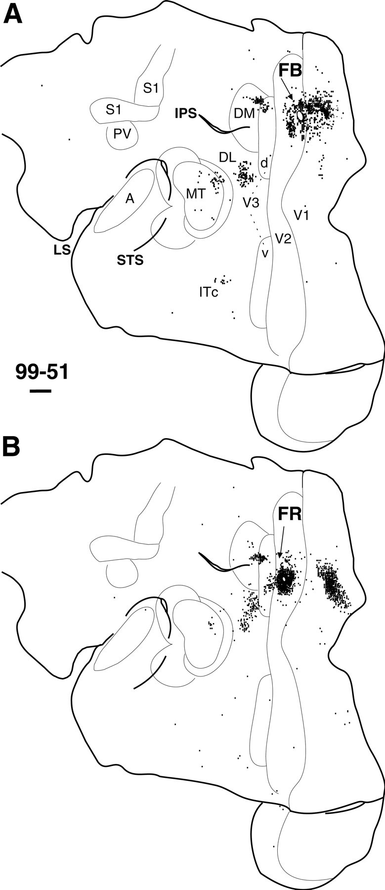
Distribution of labeled cells after an injection placed caudally (A) and rostrally (B) in dorsal V2 in the left hemisphere of marmoset 99-51. Arrows point to white ovals that represent the injection site and uptake zone of each tracer. The connection pattern is similar to dorsal V1 connections (Figs. 6, 7D). IPS, Intraparietal sulcus. Cortex was flattened as diagrammed in Figure 2. Left is rostral; up is medial. Other conventions as in Figure5.
DM and MT injections
Although the connections of DM and MT in marmosets have been described previously (Krubitzer and Kaas, 1990a,b, 1993; Rosa and Tweedale, 2000), they have not been evaluated for evidence for V3. Here, we present results from two cases in which both DM and MT injections were made and a third case with a single DM injection (Figs.9, 10). Having multiple injections allowed us to compare lower visual quadrant DM injections with upper visual quadrant MT injections to provide further evidence of the retinotopy in DM as well as V3d/v. Because MT and DM are approximately one-tenth the size of V1 and the retinotopic maps are more compressed and less detailed, the topographic patterns of connections from injections in these areas provide less precise information about the retinotopy of other areas.
Fig. 9.

Distribution of labeled cells after an injection of DY near the central representation of vision in caudolateral DM in marmoset 99-51. Anarrow points to a white oval (uptake zone) where an x marks the site of injection. Because the injection site involved parts of lateral DM devoted to both upper and lower visual quadrants, both dorsal and ventral parts of areas were labeled. Thus, both V3v and V3d project to lateralDM, as well as dorsal and ventral aspects ofV2, DL, and MT.DM connections reveal modularity within other areas. Of special interest are the different banding patterns of labeled cells in V3v and ventral V2, and somewhat within V3d and dorsal V2, and the patchy pattern within MT. Conventions as in Figure 8.
Fig. 10.

Distributions of labeled cells after FB injections in dorsal DM and DY injections in ventral MT within the same cases: 97-123 (A) and 98-4 (B).Arrows point to black ovals that represent the injection site and uptake zone of each tracer. Note that ventral MT injections (yellow) label cells in V3v, in a band-like pattern, and dorsal DM injections (blue) label V3d. A similar connection pattern was seen for dorsal and ventral DL. FEF, Frontal eye field. Other conventions as in Figure 8.
A DY injection in case 99-51 was placed at the caudolateral border of DM (Fig. 9). This site was near the expected location of the central visual field representation of DM (Rosa and Schmid, 1995; Beck and Kaas, 1998). This single injection labeled the representations of both upper and lower fields of V2, V3, and MT. Although labeled cells in V1 were expected, only a few were found, possibly because a portion of V1 was lost in the flattening process. Nevertheless, the results provide clear evidence for a V3 that projects to DM, as well as for both ventral and dorsal subdivisions of V3. These and other connections demonstrate further that DM represents both upper and lower visual quadrants.
Ventral V2 and V3v both had clusters of labeled cells forming distinct bands that matched the thickness and separation of CO dark and light bands. These bands of cells overlapped the CO dark bands of V2 and V3v (data not shown). Furthermore, the bands of labeled cells in V3v were thicker and shorter than the V2 bands of labeled cells, similar to the differences seen in CO architecture (Fig. 3). The dorsal part of V2 and V3 had fewer labeled cells, some of which clustered together in a band-like pattern.
The remaining two DM injections were both placed at the dorsal extreme of DM, just lateral to the medial wall [Fig.10A(FB),B(FB),blue], which corresponded to the representation of the lower quadrant in DM (Fig. 2) (Krubitzer and Kaas, 1993; Rosa and Schmid, 1995). In the same two cases, MT injections were placed at the lateral border of MT [Fig.10A(DY),B(DY),yellow], which corresponds to the upper quadrant. The two DM injections (Fig. 10, blue) showed similar patterns of connections). Both labeled a dense cluster of cells within the dorsal half of DM. A band of label was seen in adjacent V3d. Cells in dorsal V2 and V1 were also labeled, and in a somewhat modular fashion, with noticeable bands of cells in V2 (Fig. 10B,blue) and patchy-like blobs of labeled cells in V1 (Fig. 10,blue). Although the relationship of labeled cells to CO bands and CO blobs in V1 were not analyzed, these CO dense regions tend to provide more of the projection to DM in New World monkeys (Krubitzer and Kaas, 1993; Beck and Kaas, 1998).
The dorsal DM injections also labeled dorsal regions in MT and MTc, cells in VPP, LPP, and frontal cortex. Both cases had labeled cells in the proposed location of DLr.
Cases 97-123 and 98-4 also had injections in MT, at virtually identical locations, situated at the ventral border adjacent to MTc (Figs. 10,yellow). Within MT, labeled cells were concentrated mostly in the ventral half. In addition, there were distinct clusters of labeled cells in ventral DM, V3v, and the ventral halves of V2 and V1. In Figure 10A, labeled cells (yellow) were clustered into band-like arrays in V3v and V2. At least one focus of labeled cells was found adjacent to the lateral border of DM, probably area DI (Fig. 10, yellow). Labeled cells were also in MTc, FST, MST, and frontal cortex in regions that may correspond to the frontal eye field and frontal ventral visual motor areas (Krubitzer and Kaas, 1990b). The important result from the two cases in which injections were placed in the representation of the lower visual quadrant of one of the visual areas, DM, and the upper visual quadrant of another visual area, MT, is that the lower quadrant injections labeled V3d and the upper quadrant injections labeled V3v. Note also that the lower visual quadrant injections (blue) also labeled lower quadrant portions of V2 and V1, whereas the upper visual quadrant injections (yellow) labeled the upper quadrant of V2 and V1 (Krubitzer and Kaas, 1990b).
An injection was placed more dorsally in MT in two other cases (data not shown). In both cases, labeled neurons were found in V3d, whereas a few labeled neurons were in V3v of one of the cases where the tracer uptake zone was partially in both dorsal and ventral MT. Other connections were typical of MT.
DISCUSSION
The most important conclusion derived from the present results is that marmosets, and by implication other primates, have a V3. This V3 is not like the originally proposed V3 for monkeys in that it is discontinuous, with a gap in the center, and it is perhaps half the originally proposed size. However, it does have both a dorsal half, representing the lower visual quadrant, and a ventral half, representing the upper visual quadrant. In these respects, the V3 proposed for marmosets closely resembles the V3 proposed by Gattass et al. (1988) for macaques.
The connection pattern provides evidence that this modified V3 (V3m) represents the visual hemifield as a smaller, cruder, mirror image of V2. Both the connection pattern and the architecture suggest that V3 is modular in internal organization with band-like modules that are wider than in V2. This V3 is interconnected with V1, V2, DM, and MT (Fig. 11). V3m appears to represent a hierarchical level of processing that is higher than V1 and V2 and possibly lower than DM and MT. Part of the evidence for V3 m is architectonic, in that both dorsal and ventral divisions are apparent in flattened cortex sections processed for CO or myelin. The other part is connectional. Neurons and terminals labeled in V3d and V3v were obviously separate from those in adjoining parts of V2, DM, and DL. This separation was apparent in part because cortex was flattened and cut parallel to the surface. Thus, surface-view patterns of connections could be evaluated directly. In addition, our unique approach to the ventral part of V1 allowed us to make large injections that produced more obvious connection patterns. Thus we were able for the first time to demonstrate V1 connections with a ventral V3. These results and others are related to previous findings (see below).
Fig. 11.

A summary of connection patterns ofV3 revealed in the present study. V1 andV2 project to V3d and V3v, and V3projects to DM and MT. Reciprocal connections between V2 and V3d were observed after CTB injections in V2 (data not shown). The projections from ventral V2 to V3v are assumed but have not yet been demonstrated.
A brief history of V3
The original concept of V3 was that of a visual area along the outer border of V2, equal to V2 in size and shape, and mirroring V2 in a retinotopic organization (for review, see Kaas and Lyon, 2001). This concept was based on evidence from early studies of V1 projections in macaque monkeys (Cragg, 1969; Zeki, 1969) that dorsal V1 projects to both a dorsal V2 and a dorsal V3. Because of the greater difficulty in placing lesions in ventral V1, there was no convincing evidence for V1 projections to a separate ventral V3 in these studies, and later studies in macaques also failed to produce evidence for V1 projections to cortex in the expected location of ventral V3 (for review, seeBurkhalter et al., 1986). For this and other reasons, cortex in the location of ventral V3 was assigned by some investigators to another visual area, VP (Newsome et al., 1986). This scheme left dorsal V3 as the only V3, representing only the lower visual quadrant, and VP as another incomplete visual area representing only the upper visual quadrant. In New World monkeys, initial studies revealed V1 projections to V2 but no connectional evidence for either a dorsal or a ventral V3 (Spatz and Tigges, 1972). Subsequently, V1 projections to cortex along the dorsomedial border of V2 (Lin et al., 1982; Krubitzer and Kaas, 1993; Beck and Kaas, 1998) were attributed to DM (Allman and Kaas, 1975) rather than V3, partly because these connections included both dorsal and ventral parts of V1, and thus provided evidence for a complete representation of the visual hemifield.
Another approach has been to define V3 architectonically. V3 has been described as a densely myelinated area (Burkhalter et al., 1986). However, because cortex in the region of dorsal V3 was thought to be more densely myelinated than cortex in ventral V3, the difference was seen as further evidence that only a dorsal V3 existed. A further difficulty is that dorsal V3 has been variously defined from a broad myelinated zone of 4–5 mm in width (Girard et al., 1991; Gegenfurtner et al., 1997) to a highly variable strip as narrow as 1–2 mm (Van Essen et al., 1986). Furthermore, DM has been consistently described across primate species as a densely myelinated oval (for review, seeBeck and Kaas, 1999), and much of the proposed territory of V3d could include DM. The usefulness of myelin stains in identifying V3 was questioned by Gattass et al. (1988), when they concluded that V3 was difficult to distinguish from V2 and that V3 could not be distinguished from V3A (DM). We conclude that V3 can be identified in myelin, CO, and perhaps other (Hof and Morrison, 1995) preparations, and that V3d and V3v are similar in appearance. Yet, the difference between V3 and adjoining cortex can be subtle and is best seen in sections cut parallel to the cortical surface.
Microelectrode mapping studies of retinotopic patterns have resulted in a number of interpretations, some without any V3 (Allman and Kaas, 1975; Rosa and Tweedale, 2000), some with separate dorsal and ventral halves of V3 (Gattass et al., 1988), and some with a continuous dorsal to ventral V3 (Piñon et al., 1998; Rosa et al., 2000). These various interpretations are possible, in part, because adjoining recording sites tend to have similar receptive fields, and adjoining sites across the borders of areas have similar receptive fields. Thus, it is difficult to recognize whether recording sites have receptive fields belonging to one pattern or the other. In the instance of V3, there is the question of whether the separate representations of upper and lower parts of the visual hemifield belong together, as V3d and V3v, or correspond to separate fields, V3d and VP, or combine with parts of other areas such as DM or caudal DL (V4).
The present results support an interpretation that may apply to all primates. Separate dorsal and ventral narrow strips of cortex along the outer margin of V2 constitute ventral and dorsal halves of a modified concept of V3. Both halves are similar in architecture and connections. In addition, dorsal V3 has a densely myelinated DM along its rostral border. DM resembles V3 by having connections with V1, V2, and MT, but V3 and DM have quite different retinotopic organization. Most notably, V3 is a split area, whereas DM is whole. The split V3 in marmosets is much like the split V3 of Gattass et al. (1988) in macaques in proportions, location, and retinotopy. Previous studies without a dorsal V3 may have included some of V3d in V2 and some in DM. Previous studies with a broad V3d may have included much or all of DM in V3d. Studies with a continuous V3 may have included some of DL (V4) in V3. Much of VP would appear to be within V3v, although a recent portrayal extends VP dorsolaterally to include caudal DL (Rosa and Tweedale, 2000). Because of long-standing difficulties in defining boundaries of V3d, V3v, VP, and DM, studies of the properties of single-unit neurons in these areas need to be interpreted with caution.
Other connections of V1, V2, and DM
Although the focus of this report is on the connectional and architectonic evidence for V3, the injections in V1, V2, and DM did label other regions of cortex. V1 injections, for example, labeled a number of extrastriate regions of cortex. In addition to V3, the major connections are with V2, DM, and MT, and these connections have been described repeatedly in various primates (Krubitzer and Kaas, 1993; for review, see Casagrande and Kaas, 1994). Other connections such as those with MST and IT have been less commonly reported, but they have been noted, especially in macaques (for review, see Rockland and Van Hoesen, 1994). What is perhaps surprising is the large number of labeled neurons in IT cortex after injections of V1 in marmosets (Fig. 5). Of course some of this label could be in other areas, because the boundaries of IT are uncertain. Some have proposed (Rosa and Tweedale, 2000) that a VA area borders VP (our V3v), and if such a bordering area exists, it would clearly project to V1. Some of the cortex along the rostral border of V3v would also be occupied, according to our scheme, by DL, and some of the label attributed to IT could be in DL, but we remain uncertain about the ventral extent of DL. Nevertheless, even with these uncertainties, an impressive number of neurons in IT cortex obviously project to V1. Other labeled neurons scattered in posterior parietal cortex and cortex between DM and MT are in the territories of proposed visual areas such as DI, VPP, and LPP, but these areas have not been well defined, and further studies are needed. However, MTc does appear to be a visual area that was clearly identified by architectonic characteristics in the present study, and we present clear evidence of MTc projections to V1. Such connections have been reported for V4t of macaques (Felleman and Van Essen, 1991), corresponding to dorsal MTc.
Many of the neurons labeled by V1 injections were in locations where we had no evidence of reciprocal projections from V1. These include the IT region, MST, FST, MTc, DI, and posterior parietal cortex. This simply could be the consequence of it being more difficult to detect a sparse distribution of labeled fibers in comparison to labeled cell bodies. Yet, others have also noticed that V1 injections label neurons in locations where no fibers are labeled by such injections and have concluded that some regions of feedback connections to V1 do not receive direct projections from V1 (Felleman and Van Essen, 1991;Rockland and Van Hoesen, 1994).
Finally, our V2 and DM injections, in addition to providing evidence for V3, further demonstrated the connections of these two fields. The results are largely consistent with previous descriptions of V2 (for review, see Stepniewska and Kaas, 1996; Gattass et al., 1997) and DM (for review, see Beck and Kaas, 1999) connections. However, we can be fairly certain that our V2 or DM injections did not also include V3d, and thus the results are not contaminated by V3 connections.
Footnotes
This work was supported by National Eye Institute Grant EY 02686 and National Research Service Award Training Grant 5T32 EY07135 provided by Core Grant EY08126 to the Vision Research Center, Vanderbilt University. We thank Christine Collins, Troy Hackett, and Iwona Stepniewska for helpful comments on this manuscript, Mary Feurtado for her assistance during sterile surgical procedures and for postsurgical animal care, and Laura Trice and Mary Varghese for their help with histological procedures.
Correspondence should be addressed to Jon H. Kaas, Department of Psychology, 301 Wilson Hall, Vanderbilt University, 111 21st Avenue South, Nashville, TN 37240. E-mail:jon.kaas@vanderbilt.edu.
REFERENCES
- 1.Allman JM, Kaas JH. Representation of the visual field in striate and adjoining cortex of the owl monkey (Aotus trivirgatus). Brain Res. 1971;35:89–106. doi: 10.1016/0006-8993(71)90596-8. [DOI] [PubMed] [Google Scholar]
- 2.Allman JM, Kaas JH. A crescent-shaped cortical visual area surrounding the middle temporal (MT) in the owl monkey (Aotus trivirgatus). Brain Res. 1974;81:199–213. doi: 10.1016/0006-8993(74)90936-6. [DOI] [PubMed] [Google Scholar]
- 3.Allman JM, Kaas JH. The dorsomedial cortical visual area: a third tier area in the occipital lobe of the owl monkey (Aotus trivirgatus). Brain Res. 1975;100:473–487. doi: 10.1016/0006-8993(75)90153-5. [DOI] [PubMed] [Google Scholar]
- 4.Beck PD, Kaas JH. Cortical connections of the dorsomedial visual area in New World owl monkeys (Aotus trivirgatus) and squirrel monkeys (Saimiri sciureus). J Comp Neurol. 1998;400:18–34. doi: 10.1002/(sici)1096-9861(19981012)400:1<18::aid-cne2>3.0.co;2-w. [DOI] [PubMed] [Google Scholar]
- 5.Beck PD, Kaas JH. Cortical connections of the dorsomedial visual area in Old World macaque monkeys. J Comp Neurol. 1999;406:487–502. [PubMed] [Google Scholar]
- 6.Born RT, Tootell RBH. Segregation of global and local motion processing in primate middle temporal visual area. Nature. 1992;357:497–499. doi: 10.1038/357497a0. [DOI] [PubMed] [Google Scholar]
- 7.Brodmann K. Vergleichende Lokalisationslehre der Grosshirnrinde. Barth; Leipzig: 1909. [Google Scholar]
- 8.Bruce K, Grofova I. Notes on a light electron microscopic double-labeling method combining anterograde tracing with Phaseolus vulgaris leucoagglutinin and retrograde tracing with cholera toxin subunit B. J Neurosci Methods. 1992;45:23–33. doi: 10.1016/0165-0270(92)90040-k. [DOI] [PubMed] [Google Scholar]
- 9.Burkhalter A, Felleman DJ, Newsome WT, Van Essen DC. Anatomical and physiological asymmetries related to visual areas V3 and VP in macaque extrastriate cortex. Vision Res. 1986;26:63–80. doi: 10.1016/0042-6989(86)90071-4. [DOI] [PubMed] [Google Scholar]
- 10.Casagrande VA, Kaas JH. The afferent, intrinsic, and efferent connections of primary visual cortex in primates. In: Peters A, Rockland KS, editors. Cereb cortex, Vol 10, primary visual cortex in primates. Plenum; New York: 1994. pp. 201–259. [Google Scholar]
- 11.Cragg BG. The topography of the afferent projections in the circumstriate visual cortex of the monkey studied by the Nauta method. Vision Res. 1969;9:733–747. doi: 10.1016/0042-6989(69)90011-x. [DOI] [PubMed] [Google Scholar]
- 12.Cusick CG, Kaas JH. Surface view patterns of intrinsic and extrinsic cortical connections of area 17 in a prosimian primate. Brain Res. 1988a;458:383–388. doi: 10.1016/0006-8993(88)90483-0. [DOI] [PubMed] [Google Scholar]
- 13.Cusick CG, Kaas JH. Cortical connections of area 18 and dorsolateral visual cortex in squirrel monkeys. Vis Neurosci. 1988b;1:211–237. doi: 10.1017/s0952523800001486. [DOI] [PubMed] [Google Scholar]
- 14.Desimone R, Ungerleider LG. Multiple visual areas in the caudal superior temporal sulcus of the macaque. J Comp Neurol. 1986;248:164–189. doi: 10.1002/cne.902480203. [DOI] [PMC free article] [PubMed] [Google Scholar]
- 15.Ericson H, Blomqvist A. Tracing neuronal connections with cholera toxin subunit B: light and electron microscopic immunohistochemistry using monoclonal antibodies. J Neurosci Methods. 1988;24:225–235. doi: 10.1016/0165-0270(88)90167-7. [DOI] [PubMed] [Google Scholar]
- 16.Felleman DJ, Van Essen DC. Distributed hierarchical processing in primate cerebral cortex. Cereb Cortex. 1991;1:1–47. doi: 10.1093/cercor/1.1.1-a. [DOI] [PubMed] [Google Scholar]
- 17.Fritsches KA, Rosa MGP. Visuotopic organization of striate cortex in the marmoset monkey (Callithrix jacchus). J Comp Neurol. 1996;372:264–282. doi: 10.1002/(SICI)1096-9861(19960819)372:2<264::AID-CNE8>3.0.CO;2-1. [DOI] [PubMed] [Google Scholar]
- 18.Gallyas F. Silver staining for myelin by means of physical development. Neurol Res. 1979;1:203–209. doi: 10.1080/01616412.1979.11739553. [DOI] [PubMed] [Google Scholar]
- 19.Gattass R, Sousa APB, Gross CG. Visuotopic organization and extent of V3 and V4 of the macaque. J Neurosci. 1988;8:1831–1845. doi: 10.1523/JNEUROSCI.08-06-01831.1988. [DOI] [PMC free article] [PubMed] [Google Scholar]
- 20.Gattass R, Sousa APB, Mishkin M, Ungerleider LG. Cortical projections of area V2 in macaque. Cereb Cortex. 1997;7:110–129. doi: 10.1093/cercor/7.2.110. [DOI] [PubMed] [Google Scholar]
- 21.Gegenfurtner KR, Kiper DC, Levitt JB. Functional properties of neurons in macaque area V3. J Neurophysiol. 1997;77:1906–1923. doi: 10.1152/jn.1997.77.4.1906. [DOI] [PubMed] [Google Scholar]
- 22.Girard P, Salin PA, Bullier J. Visual activity in areas V3a and V3 during reversible inactivation of area V1 in the macaque monkey. J Neurophysiol. 1991;66:1493–1503. doi: 10.1152/jn.1991.66.5.1493. [DOI] [PubMed] [Google Scholar]
- 23.Hof PR, Morrison JH. Neurofilament protein defines regional patterns of cortical organization in the macaque monkey visual system: a quantitative immunohistochemical analysis. J Comp Neurol. 1995;352:161–186. doi: 10.1002/cne.903520202. [DOI] [PubMed] [Google Scholar]
- 24.Hubel DH, Wiesel TN. Receptive fields and functional architecture in two nonstriate visual areas (18 and 19) of the cat. J Neurophysiol. 1965;28:229–289. doi: 10.1152/jn.1965.28.2.229. [DOI] [PubMed] [Google Scholar]
- 25.Kaas JH. Theories of visual cortex organization in primates: areas of a third level. In: Norita M, Bando T, Stein BE, editors. Extrageniculostriate mechanisms underlying visually guided orientation and behavior. Elsevier; New York: 1996. pp. 213–221. [Google Scholar]
- 26.Kaas JH. Theories of visual cortex organization in primates. In: Rockland KS, Kaas JH, Peters A, editors. Cereb cortex, Vol 12, extrastriate cortex in primates. Plenum; New York: 1997. pp. 91–125. [Google Scholar]
- 27. Kaas JH, Lyon DC. Visual cortex organization in primates: theories of V3 and adjoining visual areas. Vision: from neurons to cognition Casanova C, Ptito M. 2001. Prog Brain Res, in press. [DOI] [PubMed] [Google Scholar]
- 28.Kaas JH, Morel A. Connections of visual areas of the upper temporal lobe of owl monkeys: the MT crescent and dorsal and ventral subdivisions of FST. J Neurosci. 1993;13:534–546. doi: 10.1523/JNEUROSCI.13-02-00534.1993. [DOI] [PMC free article] [PubMed] [Google Scholar]
- 29.Keizer K, Kuypers HG, Huisman AM, Dann O. Diamidino yellow dihydrochloride (DY · 2 HCl): a new fluorescent retrograde neuronal tracer, which migrates only very slowly out of the cell. Exp Brain Res. 1983;51:179–191. doi: 10.1007/BF00237193. [DOI] [PubMed] [Google Scholar]
- 30.Krubitzer LA, Kaas JH. Convergence of processing channels in the extrastriate cortex of monkeys. Vis Neurosci. 1990a;5:609–613. doi: 10.1017/s0952523800000778. [DOI] [PubMed] [Google Scholar]
- 31.Krubitzer LA, Kaas JH. Cortical connections of MT in four species of primates: areal, modular, and retinotopic patterns. Vis Neurosci. 1990b;5:165–204. doi: 10.1017/s0952523800000213. [DOI] [PubMed] [Google Scholar]
- 32.Krubitzer LA, Kaas JH. The organization and connections of somatosensory cortex in marmosets. J Neurosci. 1990c;10:952–974. doi: 10.1523/JNEUROSCI.10-03-00952.1990. [DOI] [PMC free article] [PubMed] [Google Scholar]
- 33.Krubitzer LA, Kaas JH. The dorsomedial visual area of owl monkeys: connections, myeloarchitecture, and homologies in other primates. J Comp Neurol. 1993;334:497–528. doi: 10.1002/cne.903340402. [DOI] [PubMed] [Google Scholar]
- 34.Kuypers HGJM, Bentivoglio M, Catsman-Berrevolets CE, Bharos Double retrograde neuronal labeling through divergent axon collaterals, using two fluorescent tracers with the same excitation wavelength which label different features of the cell. Exp Brain Res. 1980;40:382–392. doi: 10.1007/BF00236147. [DOI] [PubMed] [Google Scholar]
- 35.Lin CS, Weller RE, Kaas JH. Cortical connections of striate cortex in the owl monkey. J Comp Neurol. 1982;211:165–176. doi: 10.1002/cne.902110206. [DOI] [PubMed] [Google Scholar]
- 36.Lyon DC, Taub HB, Kaas JH. Connections of extrastriate visual areas in marmosets. Soc Neurosci Abstr. 1998;24:2093. [Google Scholar]
- 37.Malach R, Schirman TD, Harel M, Tootell RBH, Malonek D. Organization of intrinsic connections in owl monkey area MT. Cereb Cortex. 1997;7:386–393. doi: 10.1093/cercor/7.4.386. [DOI] [PubMed] [Google Scholar]
- 38.Malonek D, Tootell RBH, Grinvald A. Optical imaging reveals the functional architecture of neurons processing shape and motion in owl monkey area MT. Proc R Soc Lond B Biol Sci. 1994;258:109–119. doi: 10.1098/rspb.1994.0150. [DOI] [PubMed] [Google Scholar]
- 39.Maunsell JHR, Van Essen DC. The connections of the middle temporal visual area (MT) and their relationship to a cortical hierarchy in the macaque monkey. J Neurosci. 1983;3:2563–2586. doi: 10.1523/JNEUROSCI.03-12-02563.1983. [DOI] [PMC free article] [PubMed] [Google Scholar]
- 40.Newsome WT, Maunsell JHR, Van Essen DC. Ventral posterior visual area of the macaque: visual topography and areal boundaries. J Comp Neurol. 1986;252:139–153. doi: 10.1002/cne.902520202. [DOI] [PubMed] [Google Scholar]
- 41.Novikova L, Novikov L, Kellerth JO. Persistent neuronal labeling by retrograde fluorescent tracers: a comparison between Fast-Blue, Fluoro-Gold, and various dextrans. J Neurosci Methods. 1997;74:9–15. doi: 10.1016/s0165-0270(97)02227-9. [DOI] [PubMed] [Google Scholar]
- 42.Piñon MC, Gattass R, Sousa APB. Area V4 in Cebus monkey: extent and visuotopic organization. Cereb Cortex. 1998;8:685–701. doi: 10.1093/cercor/8.8.685. [DOI] [PubMed] [Google Scholar]
- 43.Rockland KS, Lund JS. Intrinsic laminar lattice connections in primate visual cortex. J Comp Neurol. 1983;216:303–318. doi: 10.1002/cne.902160307. [DOI] [PubMed] [Google Scholar]
- 44.Rockland KS, Pandya DN. Laminar origins of cortical connections of the occipital lobe in the rhesus monkey. Brain Res. 1979;179:3–20. doi: 10.1016/0006-8993(79)90485-2. [DOI] [PubMed] [Google Scholar]
- 45.Rockland KS, Van Hoesen GW. Direct temporal-occipital feedback connections to striate cortex (V1) in macaque monkeys. Cereb Cortex. 1994;4:300–313. doi: 10.1093/cercor/4.3.300. [DOI] [PubMed] [Google Scholar]
- 46.Rosa MGP, Elston GN. Visuotopic organisation and neuronal response selectivity for direction of motion in visual areas of the caudal temporal lobe of the marmoset monkey (Callithrix jacchus): middle temporal area, middle temporal crescent, and surrounding cortex. J Comp Neurol. 1998;393:505–527. [PubMed] [Google Scholar]
- 47.Rosa MGP, Schmid LM. Visual areas in the dorsal and medial extrastriate cortices of the marmoset. J Comp Neurol. 1995;359:272–299. doi: 10.1002/cne.903590207. [DOI] [PubMed] [Google Scholar]
- 48.Rosa MGP, Tweedale R. Visual areas in lateral and ventral extrastriate cortices of the marmoset monkey. J Comp Neurol. 2000;422:621–651. doi: 10.1002/1096-9861(20000710)422:4<621::aid-cne10>3.0.co;2-e. [DOI] [PubMed] [Google Scholar]
- 49.Rosa MGP, Fritsches KA, Elston GN. The second visual area in the marmoset monkey: visuotopic organization, magnification factors, architectonical boundaries, and modularity. J Comp Neurol. 1997;387:547–567. doi: 10.1002/(sici)1096-9861(19971103)387:4<547::aid-cne6>3.0.co;2-2. [DOI] [PubMed] [Google Scholar]
- 50.Rosa MG, Piñon MC, Gattass R, Sousa AP. “Third tier” ventral extrastriate cortex in the New World monkey, Cebus apella. Exp Brain Res. 2000;132:287–305. doi: 10.1007/s002210000344. [DOI] [PubMed] [Google Scholar]
- 51.Sakai ST, Stepniewska I, Qi H-X, Kaas JH. Pallidal and cerebellar afferents to pre-supplementary motor area thalamocortical neurons in the owl monkey: a multiple labeling study. J Comp Neurol. 2000;417:164–180. [PubMed] [Google Scholar]
- 52.Schmued L, Kyriakidis K, Heimer L. In vivo anterograde and retrograde axonal transport of the fluorescent-dextran-amine, Fluoro-Ruby, within CNS. Brain Res. 1990;526:127–134. doi: 10.1016/0006-8993(90)90258-d. [DOI] [PubMed] [Google Scholar]
- 53.Spatz WB, Tigges J. Species differences between Old World and New World monkeys in the organization of the striate-prestriate association. Brain Res. 1972;43:591–594. doi: 10.1016/0006-8993(72)90412-x. [DOI] [PubMed] [Google Scholar]
- 54.Stepniewska I, Kaas JH. Topographic patterns of V2 cortical connections in macaque monkeys. J Comp Neurol. 1996;371:129–152. doi: 10.1002/(SICI)1096-9861(19960715)371:1<129::AID-CNE8>3.0.CO;2-5. [DOI] [PubMed] [Google Scholar]
- 55.Tootell RBH, Hamilton SL, Silverman MS. Topography of cytochrome oxidase activity in owl monkey cortex. J Neurosci. 1985;5:2786–2800. doi: 10.1523/JNEUROSCI.05-10-02786.1985. [DOI] [PMC free article] [PubMed] [Google Scholar]
- 56.Tootell RBH, Mendola JD, Hadjikhani NK, Ledden PJ, Liu AK, Reppas JB, Sereno MI, Dale AM. Functional analysis of V3a and related areas in human visual cortex. J Neurosci. 1997;17:7060–7078. doi: 10.1523/JNEUROSCI.17-18-07060.1997. [DOI] [PMC free article] [PubMed] [Google Scholar]
- 57.Van Essen DC, Newsome WT, Maunsell JHR, Bixby JL. The projections from striate cortex (V1) to areas V2 and V3 in the macaque monkey: asymmetries, areal boundaries, and patchy connections. J Comp Neurol. 1986;244:451–480. doi: 10.1002/cne.902440405. [DOI] [PubMed] [Google Scholar]
- 58.Weller RE, Kaas JH. Retinotopic patterns of connections of area 17 with visual areas VII and MT in macaque monkeys. J Comp Neurol. 1983;220:253–279. doi: 10.1002/cne.902200302. [DOI] [PubMed] [Google Scholar]
- 59.Weller RE, Kaas JH. Cortical projections of the dorsolateral visual area in owl monkeys: the prestriate relay to inferior temporal cortex. J Comp Neurol. 1985;234:35–59. doi: 10.1002/cne.902340104. [DOI] [PubMed] [Google Scholar]
- 60.Weller RE, Kaas JH. Subdivisions and connections of superior temporal cortex in owl monkeys. J Comp Neurol. 1987;256:137–172. doi: 10.1002/cne.902560112. [DOI] [PubMed] [Google Scholar]
- 61.Wong-Riley MT. Changes in the visual system of monocularly sutured or enucleated cats demonstrable with cytochrome oxidase histochemistry. Brain Res. 1979;171:11–29. doi: 10.1016/0006-8993(79)90728-5. [DOI] [PubMed] [Google Scholar]
- 62.Zeki SM. Representations of central visual fields in prestriate cortex of monkey. Brain Res. 1969;14:271–291. doi: 10.1016/0006-8993(69)90110-3. [DOI] [PubMed] [Google Scholar]