Abstract
The texture of an object provides important cues for its recognition; however, little is known about the neural representation of texture. To investigate the representation of texture in the visual cortex, we recorded single-cell activities in area V4 of macaque monkeys. To distinguish the sensitivity of the cells to texture parameters such as density and element size from that to spatial frequency, we used texture stimuli mimicking shaded granular surfaces. We varied the size and density of the texture elements and the direction of elemental luminance gradients (apparent shadings) as stimulus parameters. Most macaque V4 cells (151 of 170; 89%) exhibited sensitivity to the texture parameters. Interestingly, 21of these cells were tuned to single shading directions (unidirectional tuning). This unidirectional tuning cannot be explained by complex-cell-like tuning for spectral power of spatial frequency, because texture stimuli with a shading direction and its opposite have almost the same spectral power. Unidirectional tunings of these cells were invariant for the position of the texture elements. Thus, this tuning cannot be explained by simple-cell-like phase-dependent spatial frequency tuning or selectivity to a particular arrangement of the elements. Moreover, the unidirectional tuning had a bias toward vertical directions, consistent with an anisotropy in the perception of three-dimensional shape from shading. This novel spatial property suggests that V4 cells are involved in extracting texture features from objects, including their three-dimensionality.
Keywords: texture, density, shape from shading, monkey, visual cortex, V4
The texture features of an object inform us about its composition and the characteristics of its surface. Thus, they provide important cues for recognition of the object and for estimation of its surface friction. Several physiological studies have dealt with visual textures as cues for segmentation of objects and their background. For example, perceptual pop-out based on texture (Knierim and van Essen, 1992; Nothdurft et al., 1999), detection of texture boundaries (von der Heydt et al., 1984; Grosof et al., 1993; Leventhal et al., 1998; Mareschal and Baker, 1998; Nothdurft et al., 2000), and figure-ground segregation of textures (Lamme, 1995;Zipser et al., 1996) have been studied in areas V1 and V2, early stages in the visual pathway. Although these studies shed light on the process of texture segmentation, the way in which texture features are represented in the visual cortical areas remains unknown.
Textures are spatially periodic patterns and are thus well characterized by spatial frequency filtering, which is regarded as one of the major tasks of the early visual cortical areas. Most textures, however, contain higher order statistical structure or local features that cannot be described in the spatial frequency domain (Julesz, 1981). To characterize textures, the visual system should extract such features as the size, shape, orientation and density of the texture elements, as well as their three-dimensionality, and associate this information with the surface properties. This means that some spatial integration of localized features is necessary to detect the density and the arrangement of texture elements. We surveyed the representation of visual textures in area V4 of the macaque because it is situated within the visual pathway for object recognition (Maunsell and Newsome, 1987) and because cells in this area have larger receptive fields than those in area V1 or V2 (Desimone and Schein, 1987), which may be suited for spatial integration of localized features.
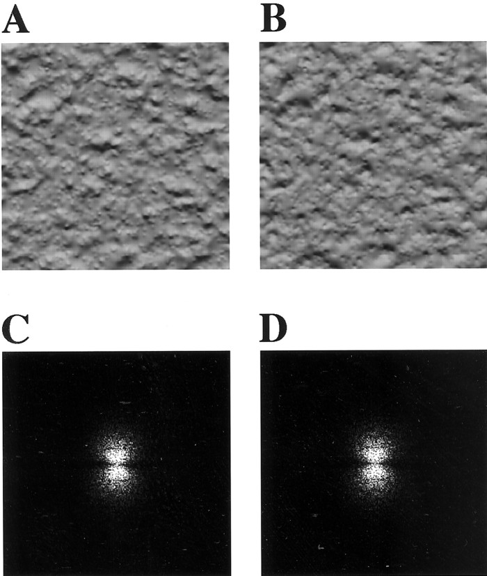
To investigate the representation of texture features distinct from that of spatial frequency, we focused on shaded granular surfaces. Textures in Figure 1, A andB, cannot be distinguished by spatial frequency filtering, because these two textures have almost the same spectral power as shown in Figure 1, C and D, respectively. Nonetheless, we distinguish them as differences in light source direction or as different three-dimensional (3-D) shapes (convexity or concavity). In the present experiments, we tested responses of single cells in area V4 to textures mimicking and simplifying shaded granular surfaces (see Figs. 2, 3). Variations in the size and density of texture elements and the direction of local luminance gradients served as stimulus parameters; our main finding was that the directionality of textural luminance gradients as well as other texture parameters (density and size of elements) is detected in area V4.
Fig. 1.
A, B, Shaded granular textures with the opposite directions of illumination generated by computer graphics. Each texture is based on the same 3-D structure model but rendered with opposite light source direction. Difference in the direction of light source is perceived as difference in the direction of illumination (downward in A and upwardin B for convex elements) or as different 3-D shapes (convexity in A andconcavity in B under downward illumination). C and D are 2-D Fourier transforms (power spectra) of textures A andB, respectively. These spectral powers of spatial frequency are indistinguishable from each other. Textures A and B therefore cannot be discriminated on the basis of tuning for the spectral power of spatial frequency as exhibited in complex cells in V1.
Fig. 2.
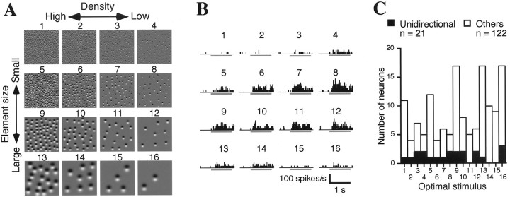
Tuning to the density and size of texture elements. A, Representative density–size stimulus set. In the horizontal row, the density of the elements doubled with each step from right toleft, whereas in the vertical column, the size (diameter) of the elements doubled, and the density decreased by one-fourth with each step from top tobottom. Thus, taking element size into account, the spacing of the elements is constant within each vertical column; i.e., the stimulus textures are scaled versions of one another. Element direction was adjusted with respect to the optimum of each cell and thus varied from cell to cell. B, Responses of a density–size-tuned cell. Histograms show the responses to stimuli corresponding to those shown in A. Bars under the histograms indicate the period of stimulus presentation (1 sec). This cell exhibits significant tuning by the stimulus set (one-way ANOVA; p < 0.01). C, Distribution of the optimal stimulus for density–size-tuned cells. Filled bars denote the unidirectional cells (described later);open bars denote all other cells.
Fig. 3.
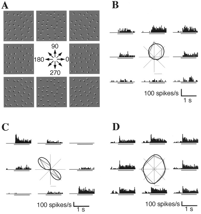
Tunings of three cells exhibiting sensitivity to the direction of the luminance gradients in the elemental patches; these cells also exhibited density–size tuning.A, Representative gradient–direction stimulus set, the basic attributes of which are the same as in Figure2A. The direction of the luminance gradient changes by 45° with each step. The density and size of the elements were adjusted to the optimum of each cell and thus varied from cell to cell. B, Unidirectional tuning in the same cell shown in Figure 2B. Each histogram shows the response to a directional stimulus corresponding to those in A. A polar plot shows the averaged discharge rate for each direction (straight thick gray line), SE (straight thin gray line), and the result of curve fitting (curved black line). The small circle at the center of the polar plot indicates spontaneous discharge level. The bar under the polar plot shows the scale of the discharge rate (20 spikes/sec). C, Bidirectional tuning. The cells in B and C both exhibit significant tuning by the stimulus set (one-way ANOVA,p < 0.01). In contrast, the responses of the cell in D exhibit no directional tuning.
MATERIALS AND METHODS
Single-cell recording. The activities of single V4 cells in two monkeys (Macaca fuscata) were recorded through recording cylinders that provided access to areas around the prelunate gyrus. The animals were required to maintain fixation within a square window 1–2° in width for a period of 1.5–2 sec to receive a liquid reward. While the animal was fixating, a visual stimulus was presented binocularly for 1 sec. Receptive fields were manually plotted using small bar stimuli or texture fragments (1 × 1−2 × 2°), and their centers and sizes were determined. For cells that did not respond to such small stimuli, only the centers of the receptive fields were determined using a larger texture fragment (4 × 4°). The centers of the receptive fields were an average of 5.3° (0–15.5°) from the fixation point in the lower visual field, whereas the sizes of the fields were an average of 5.0° (0.6–15.3°) in diameter. V4 was localized based on the cell properties and MRI images taken before the operation. Histological analysis in one of the monkeys confirmed the recording sites: electrical markings localized recorded cells at the prelunate gyrus. All animal procedures conformed to National Institutes of Health guidelines and were performed under a protocol approved by our institutional animal experiment committee.
Stimuli. Visual stimuli were 2-D achromatic patterns presented on a CRT monitor (1024 × 768 dots; 34 × 26°) placed 50 cm from the monkeys' eyes. Each stimulus was a square containing elemental patches. Each elemental patch was comprised of a positive and a negative Gaussian spot, partially overlapping. All of the patches, which were scattered randomly within the square, were the same size, and the luminance gradients were in the same direction. Each element was constructed according to the following formula:
| Equation 1 |
where L denotes luminance, x andy spatial coordinates, and s (0.05, 0.1, 0.2, 0.4°) determines the element size. The density for each element size was 3.1–25, 0.78–6.3, 0.20–1.6, and 0.049–0.39 elements per square degree, respectively. Luminance was 10 cd/m2 for the square, 20 and 0 cd/m2 for the peak and trough of the elements, and 2.5 cd/m2 for the background. The sensitivity of each cell to stimulus size was assessed using various-sized texture stimuli (0.8 × 0.8–6.4 × 6.4°; eight sizes). The size of the square was adjusted to the optimal size for each cell up to 6.4 × 6.4°, preserving the size and density of the elements. Thirty-eight percent of the recorded cells exhibited surround suppression in response to the larger texture stimuli; smaller stimuli (3.3° in average) were used in those cases. Maximal size stimuli (6.4 × 6.4°) were used for the remaining cells. The angle of the square was fixed and upright. Each cell was tested using two sets of visual stimuli: one set varied with respect to the density and size of the elements (density–size set) (Fig.2A), and the other varied in the direction of the elemental luminance gradient (gradient–direction set) (Fig.3A). Each stimulus within these sets was presented at least five times randomly interleaved with one another. The positions of the elements were fixed throughout presentations.
Data analysis. Discharge rates during the period from 20 to 1020 msec after stimulus presentation were analyzed after subtracting the baseline (−500 to 0 msec). The statistical significance of the response modulation by each stimulus set was judged by one-way ANOVA (p < 0.01).
Sensitivity to the direction of luminance gradients was characterized by fitting the following function to the profile of the directional tuning:
| Equation 2 |
where R denotes response amplitude, θthe direction of the luminance gradients, and a-e free parameters. We assumed the tuning curves to be comprised of three components, having unimodal, bimodal, and uniform distributions, respectively. For the above function, parameter a determines the amplitude of the unimodal distribution (unimodal exponentiated sinusoid), which peaked at θ = d[unidirectional component (UC)]; b determined the amplitude of the bimodal distribution (bimodal exponentiated sinusoid), which peaked at θ = d, d +π [bidirectional component (BC)]; and cdetermined the amplitude of the uniform distribution [nondirectional component (NC)] (see Fig. 4). This function represents a continuous distribution of unimodal, bimodal, and isotropic tuning profiles (see curves on polar plots in Figs. 3 and 5 for examples). Tuning direction was defined as the direction θ = d yielding the maximal value of R. Unidirectional index (UI) and bidirectional index (BI) were calculated by normalizing UC and BC to the sum of all components as follows:
| Equation 3 |
| Equation 4 |
Unidirectional cells were defined as showing statistically significant modulation (defined above) in response to a gradient–direction set and as being invariant in their directional preference with respect to the position of the elements (Fig. 6). The statistical significance of the invariance was tested by two-way ANOVA (two directions × four positions). Cells were regarded as exhibiting invariance with respect to the position of the elements when three criteria were met: the optimal directions were the same across the four element positions; the main effect of the direction factor was significant (p < 0.01), and the simple effect of the direction factor at each level of the position factor was also significant (p < 0.01).
Fig. 4.
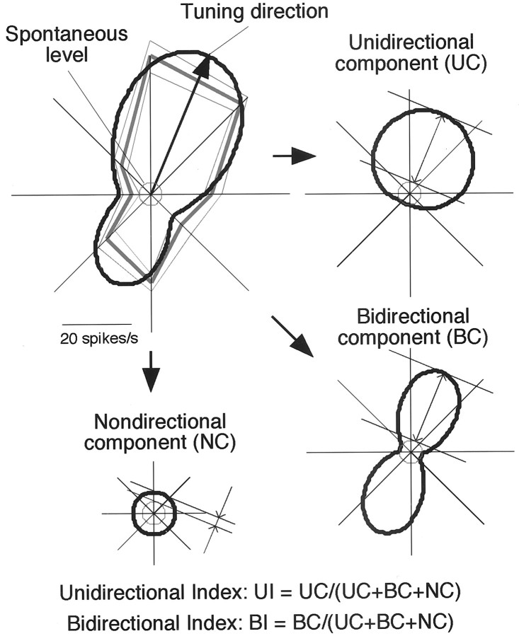
Quantification of the tuning profile with respect to the direction of elemental luminance gradients based on curve fitting. Conventions of the polar plot are the same as in Figure 3. Anarrow in the plot indicates the tuning direction. Thefitted curve is decomposed into eccentric circular, bilobed, and concentric circular curves representing UC, BC, and NC, respectively. For this cell, UC = 15.3 spikes/sec, BC = 21.2, NC = 2.8, and the maximal amplitude of the fitted curve is the sum of all three components (UC + BC + NC = 39.3). Unidirectional and bidirectional indices (UI and BI) are calculated by normalizing UC and BC to the sum of the components. For this cell, UI = 0.39 and BI = 0.54.
Fig. 5.
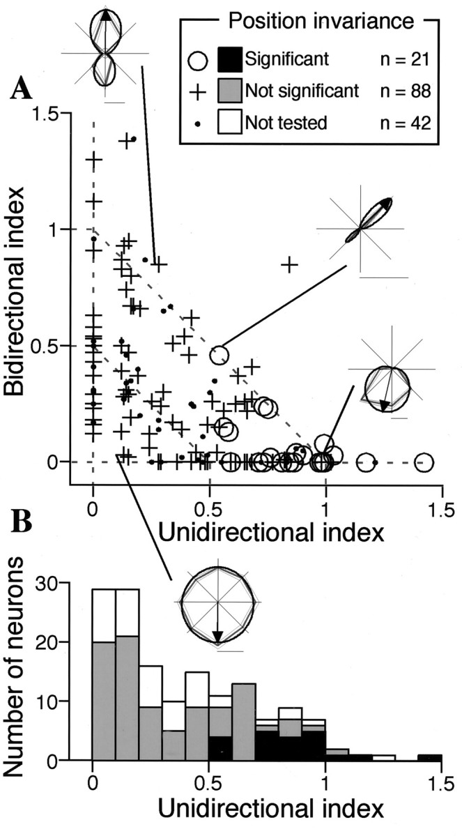
Distribution of the unidirectional and bidirectional indices. A, The bidirectional index is plotted against the unidirectional index for 151 cells that showed statistically significant modulation in response to the density–size and/or gradient–direction set. In 109 cells, invariance with respect to the position of texture element was examined (described later).Circles represent cells exhibiting invariance (unidirectional cells), and crosses represent those that do not. Four representative tuning curves are superimposed and connected with corresponding points. The broken linesconnecting each axis at a value of 1 indicate where UI + BI = 1 and the normalized amplitude of NC (NC/(UC + BC + NC)) = 0, whereas that connecting each axis at a value of 0.5 indicates where UI + BI = 0.5 and the normalized amplitude of NC is 0.5. Cells outside the former exhibited the normalized NC smaller than 0.B, Distribution of the unidirectional indices represented as a histogram.
Fig. 6.
Examples of stimuli in a stimulus set used to examine the invariance of unidirectional tuning with respect to the position of the texture elements and responses of the same cell shown in Figures 2B and 3B.A, In the horizontal rows, each stimulus has a different position of elements, but the luminance gradients are directed to the same direction. In the vertical columns, each stimulus has the same position of elements, but the luminance gradients are directed oppositely. Elements of optimal density and size were used for each cell. B, The histograms show the responses to the stimulus at the corresponding position inA. Unidirectional tuning persisted in this cell despite the changes in the position of the texture elements.
RESULTS
Responses to the texture stimuli
Using two stimulus sets that shared an optimal stimulus for each cell [density–size set (Fig.2A) and gradient–direction set (Fig.3A)], we tested the sensitivity of 170 single cells in area V4 of two macaque monkeys performing a visual fixation task to the texture parameters. Of these, 151 cells exhibited statistically significant modulation in their responses to at least one of the stimulus sets (one-way ANOVA, p < 0.01); 92 exhibited significant modulation in response to both stimulus sets; 51 exhibited modulation in response to the density–size set only; and eight cells exhibited modulation in response to the gradient–direction set only (Table1).
Table 1.
Sample of cells in the test of unidirectionality
| Stimulus set | Both | Density– size | Gradient– direction | Total |
|---|---|---|---|---|
| Significant modulation | 92 | 51 | 8 | 151 |
| Position invariance tested | 71/92 | 33/51 | 5/8 | 109/151 |
| Unidirectional | 21/71 | 0/33 | 0/5 | 21/109 |
Sensitivities to the density–size and gradient-direction stimulus sets were tested in 170 V4 cells: 151 exhibited statistically significant modulation in response to at least one of the stimulus sets; the invariance of the directional tuning with respect to the position of the elements was tested in 109 cells; 21 were classified as unidirectional.
Figure 2B illustrates the activities of a cell whose responses were significantly modulated by the density–size set in Figure 2A. The distribution of responses across the stimuli reveals that both the density and the size of the elements affected the amplitudes of the responses and that this cell responded maximally to stimulus number 8. Optimal stimuli varied among the cells, covering the entire stimulus set with some bias toward the densest stimuli (Fig. 2C) [stimulus numbers 1, 5, 9, and 13, although not statistically significant except number 9 in numbers 9–12 (χ2 test; p < 0.05)]. Figure 3B illustrates the response modulation of the same cell by the gradient–direction set in Figure 3A. In this case, the cell responded maximally to the stimulus whose luminance gradient was directed to 90°, which was the same stimulus as number 8 in Figure 2A and showed clear unidirectional tuning—i.e., the cell was minimally responsive to the oppositely oriented stimulus (270°). For comparison, Figure 3Cillustrates the responses of a cell exhibiting bidirectional tuning, in which responses to the optimal direction and its opposite were similar (in this case, 135 and 315°), whereas Figure 3Dillustrates a cell that showed no directional tuning. All of these cells showed density–size tuning.
Profiles of directional tuning
The tuning curves shown in Figure 3B–D, respectively, reflect almost completely unimodal, bimodal, and isotropic profiles, and are thus the extremes of the entire sample, between which the observed tuning curves were distributed continuously. Each tuning curve was characterized by curve fitting analysis (see Materials and Methods). We assumed UC, BC, and NC in each tuning curve, estimated the amplitude of each component based on fitting analysis, and calculated UI and BI for each cell based on the three components (Fig.4). UI and BI represent biases toward unimodal and bimodal profiles, respectively. The tuning direction of each cell was also determined based on the fitting analysis and is indicated as an arrow in the polar plots of the tuning curves.
Figure 5A illustrates the distribution of unidirectional and bidirectional indices for the 151 cells that exhibited statistically significant modulation in response to the density–size and/or gradient–direction set. As shown in the insets, cells that exhibited a large unidirectional index and a small bidirectional index had unimodal tuning curves. Cells that exhibited a large bidirectional index and a small unidirectional index had bimodal tuning curves. Bimodal tuning curves with a bias toward one of the two directions were located at intermediate positions. Both indices were small in cells not tuned to any particular direction. Cells in which the NC component had the same normalized amplitude (NC/(UC + BC + NC)) were distributed along the same line with UI + BI equaling a constant. For example, cells with normalized NC amplitudes of 0.5 and 0 fell along broken lines on which UI + BI = 0.5 and 1, respectively (Fig. 5A). Cells outside the broken line on which UI + BI = 1 had normalized NC amplitudes of <0.
Unidirectional tuning and spatial frequency filtering
The above results reveal that some V4 cells are systematically tuned to texture parameters. These tunings do not necessarily mean exclusive sensitivity to texture parameters, however. For example, cells tuned to spatial frequency, such as simple or complex cells in area V1, may exhibit similar tuning to texture, because manipulation of texture parameters inevitably changes the spectral power, the phase and the orientation of the spatial frequency components. But unidirectional tuning cannot be explained by complex-cell-like tuning for spectral power and orientation. A cell tuned to spectral power would respond equally to a luminance gradient oriented in a particular direction and to its opposite, because the two stimuli would have almost identical spectral power (Fig. 1). Indeed, cells exhibiting bidirectional tuning conform to such a scenario. Cells that showed no directional tuning, moreover, could also be tuned to spectral power, but without orientation specificity.
Unidirectional tuning may still be explained by simple-cell-like, phase-dependent tuning to spatial frequency. If a cell is sensitive to the phase of the spatial frequency components, it may appear to be tuned to a specific direction because its response would be altered by the phase shift caused by reversing the direction of the elemental luminance gradients. We examined this possibility by assessing the invariance of unidirectional tuning with respect to changes in the position of the texture elements using stimulus sets consisting of four different element positions and two opposite directions (eight stimuli). Manipulation of the position of texture elements changes the phase of the spatial frequency components without changing other parameters. As shown in Figure 6, the cell in Figure 3B continued to respond maximally to stimuli oriented at 90° and minimally to stimuli oriented at 270°, regardless of the position of the elements. This indicates that the unidirectional tuning was unaffected by the phase shift and cannot, therefore, be explained by simple cell-like, phase-dependent, spatial frequency filtering. This finding also excludes the possibility that unidirectional tuning of this neuron was a consequence of a selective response to the conjunction of a particular position and direction of the elements.
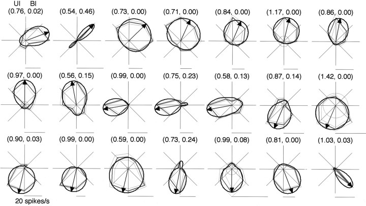
We tested the invariance of the directional tuning with respect to the position of the elements in 109 of the 151 cells that exhibited statistically significant modulation in response to the density–size and/or gradient–direction set: 71 exhibited significant modulation in response to both stimulus sets; 33 exhibited modulation in response to the density–size set only; and five exhibited modulation in response to the gradient–direction set only (Table 1). We could not test the invariance of the remaining 42 cells because of instability of the recordings. We defined unidirectional cells based on statistical criteria (see Materials and Methods), and 21 of the 76 cells that exhibited modulation in response to the gradient–direction set were classified as unidirectional (Table 1). There was considerable variation in the shape of the tuning curves, but they all had a clear bias toward a particular direction (Fig.7). Note that the minimal response of each cell was quite small; thus cellular responses cannot be attributed to the square background of the texture elements, which was common to all of the stimuli. As can be seen in Figure 5, all unidirectional cells had a unidirectional index higher than 0.5 and showed statistically significant modulation in response to the density–size set. The optimal stimuli in the density–size set were evenly distributed across the entire set (Fig. 2C, filled bars). Because the unidirectional tuning cannot be explained by spatial frequency filtering, their density–size tunings would reflect the specific sensitivities of a cell to the density and size of the texture elements.
Fig. 7.
Tuning curves of 21 unidirectional cells for the direction of the elemental luminance gradients. Conventions of the polar plots are the same as in Figures 3 and 4. Numbersabove each plot indicate the UI and BI, respectively. The polar plots are aligned in counterclockwise order of the tuning direction fromtop left to bottom right.
Receptive field properties of unidirectional cells
Eight of the unidirectional cells did not respond to the small stimuli used for receptive field mapping; in those cases larger textures were used to determine only the centers of the receptive fields, which exhibited an average of 5.0° (2.6–6.4°) of eccentricity. For the other 13 unidirectional cells, the centers of the receptive fields exhibited an average of 5.2° (2.6–7.2°) in eccentricity, and the fields were 4.4° (2.6–6.6°) in diameter. For most of these unidirectional cells, we used maximal size stimuli, which covered the entire receptive field center; nonetheless four cells exhibited surround suppression. In those cases, smaller stimuli (4–4.8°) were used. An average of 124.5 (1.3–335.1) texture elements fell within the receptive fields of the 13 cells for which we could measure the size of the receptive field. In only three cells was the number of elements falling within the receptive field <10 (1.3, 1.4, and 6.5). No significant correlation was observed between preferred stimulus density and the size or eccentricity of the receptive fields of the unidirectional cells.
Tuning directions of unidirectional cells
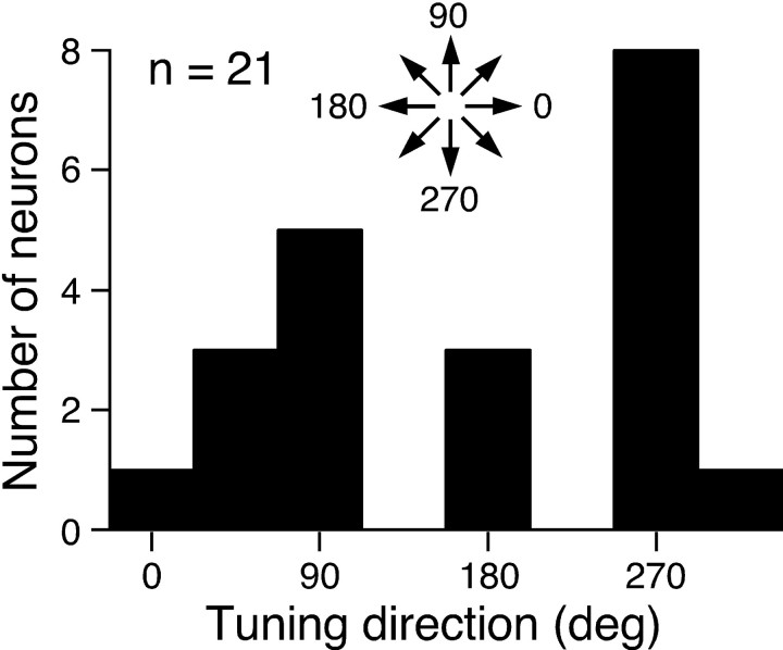
The data presented so far have shown that the texture tuning of the unidirectional cells cannot be explained by spatial frequency filtering, but instead reflect novel spatial properties of these cells, which likely represent texture parameters. A question yet to be addressed is: what is the functional role of unidirectional tuning? One interesting property of the unidirectional cells suggests their involvement in recovering 3-D shape from shading. Figure8 illustrates the distribution of the tuning directions of the unidirectional cells. The distribution is clearly biased toward upward (90°) and downward (270°) orientations—i.e., vertical directions—which is consistent with psychophysical data showing that the perception of shape from shading in humans has an anisotropy for the direction of the luminance gradient (Ramachandran, 1988; Kleffner and Ramachandran, 1992). The statistical significance of this bias was tested using directional statistics (Mardia and Jupp, 2000), which showed that distributions significantly deviated from uniformity when the peaks of their bimodal bias were oppositely oriented (the Reyleigh test, 2n R2 = 11.4;p < 0.01).
Fig. 8.
Distribution of the tuning direction of the unidirectional cells tested by the gradient–direction set. A clear bias toward vertical directions was observed (the Reyleigh test;p < 0.01).
Responses to conventional stimuli
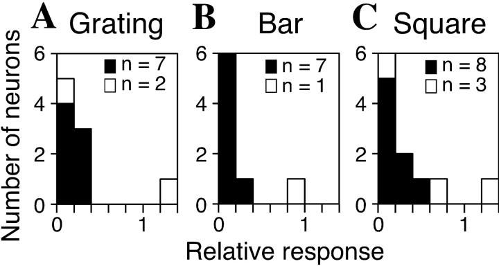
We also tested the responses of the cells to sine wave gratings, bars, and squares (conventional stimuli). Three types of stimulus sets were used: sine wave gratings (10 cd/m2 ± 10 cd/m2) of five spatial frequencies (0.47–7.5 cycles/degree), and four orientations (5×4 = 20 stimuli) were used with 72 cells; bars (10 cd/m2, optimal size) oriented eight ways were used with 88 cells; and squares (10 cd/m2) of six sizes (0.25–8°) were used with 101 cells. Most of the unidirectional cells tested showed much weaker responses to gratings (7 of 9), bars (7 of 8), and squares (8 of 11) than to the optimal texture stimuli (Mann–Whitney Utest, p < 0.01) (Fig.9), which further supports the notion that unidirectional cells are not spatial frequency filters and are not responsive to simple stimuli, stimulus edges, or temporal luminance changes. For approximately one-fourth of the remaining cells (13 of 63 for gratings, 24 of 79 for bars, and 22 of 87 for squares), the responses to the conventional stimuli were also significantly weaker, although they exhibited significant modulation in response to the density–size and/or gradient–direction set, suggesting that these cells had specificity for various granular patterns and were thus coding the texture parameters, not spatial frequency. None of the cells that did not show statistically significant modulation in response to either the density–size or the gradient–direction set showed a significant decrease in response to the conventional stimuli (10 cells for gratings, 10 cells for bars, and 12 cells for squares).
Fig. 9.
Responses of unidirectional cells to three types of conventional stimuli. Shown are the distributions of the best responses to sine wave gratings (A), bars (B), and squares (C) normalized to the best response to the texture stimuli. Filled bars illustrate that the response to the conventional stimulus was significantly weaker than that to the optimal texture stimulus (Mann–Whitney U test; p < 0.01).
Responses to modified stimuli
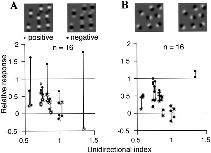
The characteristics of the unidirectional cells were assessed further by manipulating the elements of the texture stimuli (modified stimuli). In a single experimental session, we compared the responses of individual cells when presented their optimal stimulus and several modified stimuli. Figure10A illustrates the responses of 16 unidirectional cells to stimuli whose elements were replaced with even Gabor functions (Gabor stimuli); we aimed to remove directionality from each element, while keeping the local and global spectral power of the spatial frequency and mean luminance unchanged. The centers of the Gabor patches were either positive or negative. Response amplitudes normalized to those evoked by optimal texture stimuli were plotted against the unidirectional index. Each vertical line between a pair of data points connects responses of a single cell to positive and negative Gabor stimuli represented by open and filled circles, respectively. Most cells showed smaller responses to this type of stimulus than to the optimal texture stimuli—indeed several cells did not respond at all—although three cells that responded more strongly to the negative Gabor stimuli showed more complex behavior. Figure 10B illustrates responses of the same 16 unidirectional cells to stimuli whose elemental patches were randomly directed (randomized stimuli). In this case, two complementary stimuli with oppositely oriented elements were used. Again most cells exhibited weaker responses to these stimuli, although there are differences in the relative responses across individual cells.
Fig. 10.
Responses of the unidirectional cells to stimuli in which the elements were modified from the optimal stimulus. Response amplitudes normalized to those evoked by optimal stimuli are plotted against the unidirectional index. A vertical line between two points connects responses of a cell to two complementary stimuli. Circles overlapping the data points indicate significant decreases in the responses (Mann– Whitney U test; p < 0.01).A, Texture elements were replaced with even Gabor patches. B, The direction of each elemental luminance gradient was randomized.
The three cells that responded more strongly to negative Gabor stimuli showed large differences (1.1, 1.4, 2.2) between their relative responses to the complementary Gabor stimuli. For the remaining 13 cells, the differences between the relative responses to the complementary stimuli were small: 0.21 on average (0.03–0.44) for Gabor stimuli and 0.20 on average (0.01–0.53) for randomized stimuli. Weak specificity to complementary stimuli indicates that the cells were insensitive to the manipulation of elements that did not change the total strength of the directional components, further supporting the idea that the cells are insensitive to certain specific patterns. On the other hand, the strong specificity to the complementary Gabor stimuli observed in conjunction with the unidirectional tuning in the three cells suggests that more complicated stimulus parameters are involved in determining responses of some V4 cells.
With respect to the 13 cells that did not show large differences between responses to the complementary Gabor stimuli, cells exhibiting stronger unidirectional tuning tended to respond significantly more weakly to the modified stimuli (r = −0.488,p < 0.05 for Gabor stimuli; r = −0.515, p < 0.01 for randomized stimuli). In these 13 cells, responses (averages of responses to complementary stimuli) to Gabor stimuli were strongly correlated with those to randomized stimuli (r = 0.842; p < 0.001), indicating that each cell responded similarly to different types of the modified stimuli. Five of the 16 unidirectional cells showed significantly (Mann–Whitney U test, p < 0.01) smaller responses to all four modified stimuli than to optimal texture stimuli; six cells showed significantly smaller responses to three stimuli and four cells to one or two stimuli. The responses of one cell were not significantly diminished for any of the modified stimuli. The modified stimuli contained luminance gradients oriented to the preferred direction of each cell together with gradients oriented to the opposite or other directions. The differences in the relative responses across the cells may be attributable to differences in the sensitivity to these preferred or nonpreferred directional components in the modified stimuli, which are correlated with the strength of directional tuning. We found no relationship between the responses to the modified stimuli and tuning for density, size, or directionality of the texture elements. Also, there was no correlation between the relative responses to the modified stimuli and those to conventional stimuli, which were usually very weak.
DISCUSSION
The present results provide evidence that several texture features are represented in area V4. In particular, unidirectional tuning to the textural luminance gradients raises the possibility that area V4 is involved in the recovery of three-dimensionality from shading. This notion is strengthened by the bias in the tuning direction consistent with an anisotropy observed in the perception of 3-D shape from shading (Ramachandran, 1988; Kleffner and Ramachandran, 1992). Our results also support the idea that perception of texture cannot be fully decomposed into the spectral power of spatial frequency (Julesz, 1981). The density tuning of the cells is consistent with a psychophysical study of texture-density aftereffect (Durgin and Huk, 1997), which suggests the existence of texture-density detectors distinct from spatial frequency filters.
It is well known that many V4 cells respond to conventional spatial stimuli, such as sine wave gratings and bars (Desimone and Schein, 1987). However, several physiological studies have demonstrated that area V4 contains cells that show specificity for spatially complex visual stimuli, such as non-Cartesian gratings (Gallant et al., 1993,1996), complex shapes (Kobatake and Tanaka, 1994), and contour curvatures (Pasupathy and Connor, 1999). Likewise, some neurons recorded in the present study, most unidirectional cells in particular, did not respond to the conventional stimuli but exhibited strong specificity for texture stimuli. The texture stimuli we used can be regarded as containing a higher order statistical structure, an offshoot of the Glass pattern, which can be generated by parallel translation of Gaussian spots, accompanied by reversal of their contrast. Unidirectional cells may thus be placed among the detectors of higher order statistical structures. The directionality of the elemental luminance gradient may be locally detected in earlier visual areas, i.e., in V1 and V2. Considering the smaller receptive fields of neurons in these areas, it is unlikely that they exhibit tuning for the directionality of multiple luminance gradients used in the present study. It may be that directionality of shading is detected locally at these earlier stages and then integrated in area V4.
Several nonlinear models have been proposed to explain texture segregation (Bergen and Landy, 1991) or Glass pattern perception (Wilson and Wilkinson, 1998). These nonlinear models use a rectification process that corresponds to the role of complex cells in area V1. But because the directional information of elemental luminance gradients is eliminated by the rectification, such models cannot encode the directionality of textural luminance gradients. On the other hand, a neural network model of 3-D shape perception from shading was able to discriminate surface curvature using shading cues without the need for complex cells, whereas a simple-cell-like structure emerged in a hidden layer (Lehky and Sejnowski, 1988, 1990). This model is consistent with our findings, suggesting the processing of 3-D shapes from shading or some other feature detection process is not performed by complex cells.
According to psychophysical studies of perception of shape from shading, which entailed performance of a visual search task, vertical shadings induce more vivid perception of 3-D surfaces than horizontal shadings (Ramachandran, 1988; Kleffner and Ramachandran, 1992). This anisotropy may reflect an adaptation to the fact that sunlight usually comes from above, and vertical shading is more common than horizontal in the environment. The biases observed in tuning direction therefore suggest that unidirectional cells may play a functional role in the recovery of 3-D shape from shading, which may include finding the light source direction, assigning convexity or concavity, or distinguishing shading and surface reflectance. However, because of an ambiguity in our stimuli, e.g., a stimulus of 90° can be perceived as convexity under upward illumination or concavity under downward illumination, it will be necessary to use some other cue for three-dimensionality to determine the functional role of unidirectional cells in the representation of 3-D shapes.
Finally, one recent fMRI study found that signal amplitudes differed between responses to textures composed of vertical and horizontal shadings (Humphrey et al., 1997), which is consistent with the bias we observed in the tuning direction of unidirectional cells, and suggests that the human visual system may also contain unidirectional cells with similar directional biases.
Footnotes
This work was supported by the “Research for the Future” Program of the Japan Society for the Promotion of Science. We thank I. Murakami and M. Ito for critical comments on this manuscript, M. Togawa and N. Takahashi for technical assistance, and The Cooperation Research Program of Primate Research Institute (Kyoto University, Inuyama, Japan) for providing monkeys.
Correspondence should be addressed to Dr. Akitoshi Hanazawa, Laboratory of Neural Control, National Institute for Physiological Sciences, Myodaiji, Okazaki, Aichi 444-8585, Japan. E-mail: hanazawa@nips.ac.jp.
REFERENCES
- 1.Bergen JR, Landy MS. Computational modeling of visual texture segregation. In: Landy MS, Movshon JA, editors. Computational models of visual processing. MIT; Cambridge: 1991. pp. 253–271. [Google Scholar]
- 2.Desimone R, Schein SJ. Visual properties of neurons in area V4 of the macaque: sensitivity to stimulus form. J Neurophysiol. 1987;57:835–868. doi: 10.1152/jn.1987.57.3.835. [DOI] [PubMed] [Google Scholar]
- 3.Durgin FH, Huk AC. Texture density aftereffects in the perception of artificial and natural textures. Vision Res. 1997;37:3273–3282. doi: 10.1016/s0042-6989(97)00126-0. [DOI] [PubMed] [Google Scholar]
- 4.Gallant JL, Braun J, Van Essen DC. Selectivity for polar, hyperbolic, and Cartesian gratings in macaque visual cortex. Science. 1993;259:100–103. doi: 10.1126/science.8418487. [DOI] [PubMed] [Google Scholar]
- 5.Gallant JL, Connor CE, Rakshit S, Lewis JW, Van Essen DC. Neural responses to polar, hyperbolic, and Cartesian gratings in area V4 of the macaque monkey. J Neurophysiol. 1996;76:2718–2739. doi: 10.1152/jn.1996.76.4.2718. [DOI] [PubMed] [Google Scholar]
- 6.Grosof DH, Shapley RM, Hawken MJ. Macaque V1 neurons can signal “illusory” contours. Nature. 1993;365:550–552. doi: 10.1038/365550a0. [DOI] [PubMed] [Google Scholar]
- 7.Humphrey GK, Goodale MA, Bowen CV, Gati JS, Vilis T, Rutt BK, Menon RS. Differences in perceived shape from shading correlate with activity in early visual areas. Curr Biol. 1997;7:144–147. doi: 10.1016/s0960-9822(06)00058-3. [DOI] [PubMed] [Google Scholar]
- 8.Julesz B. Textons, the elements of texture perception, and their interactions. Nature. 1981;290:91–97. doi: 10.1038/290091a0. [DOI] [PubMed] [Google Scholar]
- 9.Kleffner DA, Ramachandran VS. On the perception of shape from shading. Percept Psychophys. 1992;52:18–36. doi: 10.3758/bf03206757. [DOI] [PubMed] [Google Scholar]
- 10.Knierim JJ, van Essen DC. Neuronal responses to static texture patterns in area V1 of the alert macaque monkey. J Neurophysiol. 1992;67:961–980. doi: 10.1152/jn.1992.67.4.961. [DOI] [PubMed] [Google Scholar]
- 11.Kobatake E, Tanaka K. Neuronal selectivities to complex object features in the ventral visual pathway of the macaque cerebral cortex. J Neurophysiol. 1994;71:856–867. doi: 10.1152/jn.1994.71.3.856. [DOI] [PubMed] [Google Scholar]
- 12.Lamme VA. The neurophysiology of figure-ground segregation in primary visual cortex. J Neurosci. 1995;15:1605–1615. doi: 10.1523/JNEUROSCI.15-02-01605.1995. [DOI] [PMC free article] [PubMed] [Google Scholar]
- 13.Lehky SR, Sejnowski TJ. Network model of shape-from-shading: neural function arises from both receptive and projective fields. Nature. 1988;333:452–454. doi: 10.1038/333452a0. [DOI] [PubMed] [Google Scholar]
- 14.Lehky SR, Sejnowski TJ. Neural network model of visual cortex for determining surface curvature from images of shaded surfaces. Proc R Soc Lond B Biol Sci. 1990;240:251–278. doi: 10.1098/rspb.1990.0037. [DOI] [PubMed] [Google Scholar]
- 15.Leventhal AG, Wang Y, Schmolesky MT, Zhou Y. Neural correlates of boundary perception. Vis Neurosci. 1998;15:1107–1118. doi: 10.1017/s0952523898156110. [DOI] [PubMed] [Google Scholar]
- 16.Mardia KV, Jupp PE. Directional statistics. Wiley; Chichester: 2000. [Google Scholar]
- 17.Mareschal I, Baker CL. A cortical locus for the processing of contrast-defined contours. Nat Neurosci. 1998;1:150–154. doi: 10.1038/401. [DOI] [PubMed] [Google Scholar]
- 18.Maunsell JH, Newsome WT. Visual processing in monkey extrastriate cortex. Annu Rev Neurosci. 1987;10:363–401. doi: 10.1146/annurev.ne.10.030187.002051. [DOI] [PubMed] [Google Scholar]
- 19.Nothdurft HC, Gallant JL, Van Essen DC. Response modulation by texture surround in primate area V1: correlates of “popout” under anesthesia. Vis Neurosci. 1999;16:15–34. doi: 10.1017/s0952523899156189. [DOI] [PubMed] [Google Scholar]
- 20.Nothdurft HC, Gallant JL, Van Essen DC. Response profiles to texture border patterns in area V1. Vis Neurosci. 2000;17:421–436. doi: 10.1017/s0952523800173092. [DOI] [PubMed] [Google Scholar]
- 21.Pasupathy A, Connor CE. Responses to contour features in macaque area V4. J Neurophysiol. 1999;82:2490–2502. doi: 10.1152/jn.1999.82.5.2490. [DOI] [PubMed] [Google Scholar]
- 22.Ramachandran VS. Perception of shape from shading. Nature. 1988;331:163–166. doi: 10.1038/331163a0. [DOI] [PubMed] [Google Scholar]
- 23.von der Heydt R, Peterhans E, Baumgartner G. Illusory contours and cortical neuron responses. Science. 1984;224:1260–1262. doi: 10.1126/science.6539501. [DOI] [PubMed] [Google Scholar]
- 24.Wilson HR, Wilkinson F. Detection of global structure in Glass patterns: implications for form vision. Vision Res. 1998;38:2933–2947. doi: 10.1016/s0042-6989(98)00109-6. [DOI] [PubMed] [Google Scholar]
- 25.Zipser K, Lamme VA, Schiller PH. Contextual modulation in primary visual cortex. J Neurosci. 1996;16:7376–7389. doi: 10.1523/JNEUROSCI.16-22-07376.1996. [DOI] [PMC free article] [PubMed] [Google Scholar]


