

Abstract
Herein, a core–shell dual metal–organic framework (MOF) heterointerface is synthesized. The Prussian blue (PB) MOF acts as a core for the growth of a porphyrin-doped MOF which is named PB@MOF. Porphyrins can significantly enhance the transfer of photoinspired electrons from PB and suppress the recombination of electrons and holes, thus enhancing the photocatalytic properties and consequently promoting the yields of singlet oxygen rapidly under 660 nm illumination. PB@MOF can exhibit a better photothermal conversion efficiency up to 29.9% under 808 nm near-infrared irradiation (NIR). The PB@MOF heterointerface can possess excellent antibacterial efficacies of 99.31% and 98.68% opposed to Staphylococcus aureus and Escherichia coli, separately, under the dual light illumination of 808 nm NIR and 660 nm red light for 10 min. Furthermore, the trace amount of Fe and Zr ions can trigger the immune system to favor wound healing, promising that PB@MOF achieves the rapid therapy of bacterial infected wounds and environmental disinfection.
Short abstract
The dual metal−organic framework (PB@MOF) heterostructure with both photothermal and photodynamic effects can be used to kill bacteria rapidly and promote wound healing effectively.
Introduction
Skin is an important barrier that prevents microorganisms from invading the human body.1 However, this function will disappear if skin is damaged. If this occurs, microorganisms can easily invade and form colonies, which can lead to wound infection and hinder the healing process of a wound.2 The most common bacterial species in wound infections are Staphylococcus aureus (S. aureus) and Escherichia coli (E. coli). S. aureus often causes severe sepsis, and E. coli can damage blood vessels and the heart.3,4 Therefore, how to kill pathogenic bacteria is a problem that scientists have extensively explored. At present, the main antibacterial agent is antibiotics, such as vancomycin, amoxicillin, and gentamicin; however, antibiotics cannot achieve a rapid sterilization effect, and the abuse of antibiotics not only has strong toxic side effects on the body but also leads to the emergence of drug-resistant bacteria.5,6 More than 13 million people worldwide die each year from new infectious diseases or diseases that were previously thought to be under control.7
Therefore, determining how to develop a fast and effective sterilization strategy without using antibiotics is extremely urgent. In recent years, artificially synthesized materials with excellent photocatalytic properties or photothermal properties, such as Ti3C28 and MoS2,9 have been attracting increased attention because some of them can produce reactive oxygen species (1O2, OH, •O2–) to kill bacteria when photoinspired electrons and holes are captured by surrounding oxygen, which has evolved into photodynamic therapy (PDT) for curing cancer or killing germs through the destruction of DNA, enzymes, and proteins.10 The surface temperature of other materials, however, can rise to some extent under light irradiation due to the produced hyperthermia during this course, which can be employed to inactivate bacteria or cancer cells, i.e., so-called photothermal therapy (PTT).11,12 Currently, it is difficult for single PDT or PTT from these artificial materials to achieve a satisfied therapeutic effect without impairing surrounding tissues, due to either insufficient ROS content or higher temperature.13,14 In contrast, the combination of both PDT and PTT can achieve a better efficacy than for a single therapy.15 Therefore, it is necessary to develop new artificial biomaterials with excellent photocatalytic and photothermal effects as well as desired biological functions. However, few studies have been reported on these kinds of materials.
A metal–organic framework (MOF) is a porous crystalline material comprising metal ions and organic ligands through coordination bonds, and MOFs have been used in biomedicine, energy power, and chemical catalysis.16−18 In biomedicine, MOFs are extensively used in medicine carriers because of the large specific surface, porosity, and chemical stability,19 and some MOFs containing transition metal ions (ferrum, manganese) are used for in vivo imaging.20,21 Due to the tunable metal ions and organic ligands, the MOF not only integrates the photosensitizer into the periodic array but also encapsulates some of the nanoparticles.22,23 The incorporation of the photosensitizer as a ligand into the MOF not only limits the self-quenching phenomenon of the photosensitizer but also imparts new properties to the MOF.24,25
Porphyrins which can produce 1O2 have been extensively studied as a metal organic framework of single ligands, such as PCN-224, PCN-223, etc.,26−28 and the reactive oxygen species (ROS) yield in MOFs is higher than that of individual porphyrin ligands.
The Prussian blue (PB) MOF, as a kind of photothermal material which is clinically ratified by the US Food and Drug Administration (FDA),29 has attracted abundant attention. Prussian blue MOFs are extensively used in PTT on account of their simple preparation, good photothermal effect, low biotoxicity, and biodegradability.
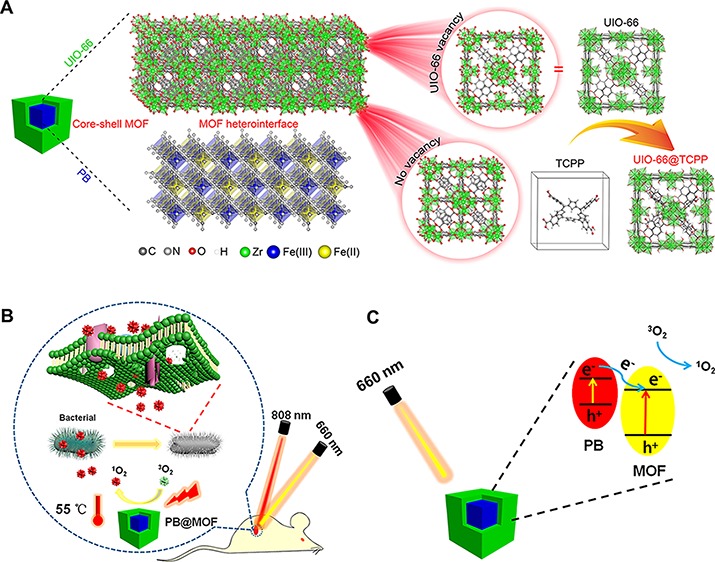
In view of these factors, we synthesized a core–shell dual MOF heterostructure using the PB MOF as a core and a porphyrin-doped UIO-66-TCPP MOF as a shell, named PB@MOF [TCPP, tetrakis(4-carboxyphenyl)porphyrin]. To endow it with both PTT and PDT properties, a metal–organic framework (MOF) using a porphyrin group is used as the shell; due to the existence of defects in the UIO-66, porphyrin ligands are incorporated into the crystal structure of UIO-66.30−32 The core–shell structure of PB@MOF is shown in Scheme 1A. Through photothermal and photodynamic synergy, the dual MOF structure can achieve the effect of killing more than 99% of both the S. aureus and E. coli within 10 min of irradiation by 808 + 660 nm mixed light (dual light). The rapid sterilization mechanism of PB@MOF is shown in Scheme 1B, and the rational photocatalytic mechanism for PB@MOF heterojunction photocatalysts is shown in Scheme 1C.
Scheme 1. Schematic Diagram of the Structure and Antibacterial Mechanism of PB@MOF.

(A) Schematic illustration of the core–shell structure of PB@MOF. (B) Schematic illustration of the bacteria killing processes with the PB@MOF under dual light irradiation. (C) Schematic illustration of rational photocatalytic mechanism for PB@MOF heterojunction photocatalysts.
Results and Discussion
Synthesis and Characterization of PB@MOF
In this work, porphyrin-doped UIO-66 MOFs (UIO-66-TCPP, MOF) are synthesized; according to the transmission electron microscopy (TEM) (Figure S1A) and scanning electron microscopy (SEM) pictures (Figure S1B), the average size of the MOF is about 70 nm. The 1H nuclear magnetic spectroscopy (NMR) spectrum of the MOF proves that TCPP is incorporated into the UIO-66 crystal, and the ratio of BDC to TCPP is 32:1 (Figure S2; BDC, terephthalic acid). PB MOFs are prepared from K3[Fe(CN)6] and polyvinylpyrrolidone (PVP). According to the TEM (Figure 1A) and SEM pictures (Figure S3A), the synthesized PB MOFs show a cubic morphology, and the average size of PB is approximately 260 nm. After being coated with the porphyrin-doped UIO-66 MOF, the synthesized PB@MOF still exhibits a cubic morphology, and the average size of the PB@MOF is approximately 300 nm (Figure 1B and Figure S3B). In addition, the core–shell structure can be seen explicitly, and the thickness of the outer MOF shell is approximately 20 nm, which proves the successful synthesis of PB@MOF (Figure 1B). We also have considered whether it is possible to use other porphyrin-based MOFs as shells, such as PCN-224, but we find it difficult for PB@PCN-224 to form a core–shell structure (Figure S4). The element compositions of the dual MOFs can also be determined by TEM–EDX spectra and the EDX elemental mapping data (EDX, energy-dispersive X-ray spectroscopy). It is evident that Zr appears in the EDX obtained from PB@MOF (Figure 1C). According to the EDX mapping images (Figure 1D), the elemental Zr is located in the shell; the elemental Fe and N are mainly located in the nucleus, and the elemental C and O are located in the whole nanostructure. To demonstrate the successful synthesis of the dual MOF further, X-ray diffraction (XRD) pictures of the PB@MOF, PB, and MOF were performed. The peaks obtained from PB can be indexed to the face-centered cubic lattice of Fe4[Fe(CN)6]3 nanocubes according to JCPDS 73-0687 (Figure 1E).29 When porphyrin-doped MOF is grown on PB, some new peaks appear at 7.36° and 8.48°, which show a great match with the diffraction peak of the pure porphyrin-doped MOF.33 These results reveal the formation of the MOF phase onto the surfaces of PB. To study the nucleation process of the MOF on the surface of PB, we perform the TEM of PB@MOF for different reaction times. We find that there is already a layer of the MOF on the surface of PB at 0.5 h of reaction, and there are almost no separate MOF nanoparticles in the solution. With the extension of time, the thickness of the MOF on the surface of PB increases, and the XRD results also indicated the formation of the MOF (Figure S5). According to the FT-IR spectrum (Figure 1F), the telescopic oscillation of the C≡N bond shows a strong peak at 2090 cm–1, which is vested in the PB MOF, and a peak at 499 cm–1 related to the bending of Fe—C≡N—Fe can be perceived.29 In the spectrum of the porphyrin-doped sample, the peak at 1581 and 1400 cm–1 is related to the asymmetric and symmetrical vibrations of O—C=O belonging to the organic ligand, respectively. The oscillation of C=C bonds in the benzene ring is located at 1506 cm–1, and the C—H band in the benzene ring is located at 770–702 cm–1.34 The synthesized dual MOF of PB@MOF possesses all the characteristic peaks mentioned above, which can further illustrate the successful synthesis of the core–shell structure. The porosity of PB@MOF is examined by a nitrogen adsorption and desorption experiment at 77 K. On the basis of Figure 1G, the Brunauer−Emmett−Teller (BET) surface area of PB@MOF is 362.3 m2 g–1, and the pore size distribution of PB@MOF is composed of micropores (1.47, 1.61, and 1.85 nm) and mesoporous pores (the pore size distribution centered at 2.64 nm). At the same time, we test the BET of different materials (PB, UIO-66, and MOF) (details are described in Figure S6); by comparing the BET and pore diameter of these materials, we find that the insertion of PB and TCPP reduced the BET of PB@MOF but hardly changed its pore size distribution. To further determine the elemental compositions of the PB@MOF structure, XPS was performed (details are described in Figure S7).
Figure 1.

Basic morphology of PB, PB@MOF, and MOF. TEM pictures of (A) PB and (B) PB@MOF, scale bar = 50 nm. (C) TEM-EDX of PB@MOFs. (D) EDX elemental mapping images of PB@MOFs. (E) XRD patterns and (F) FT-IR spectra of PB, PB@MOF, and MOF. (G) The isotherm of nitrogen adsorption–desorption and the pore size distribution of PB@MOF were obtained at 77 K.
The MOF with a core–shell structure has attracted considerable attention. First, due to the MOF’s shell coating, it can avoid the aggregation and migration of nanostructures with high surface energy and small size, thus maintaining the chemical structure and stability of the nanostructure core.35 In addition, this core–shell structure can effectively combine the advantages of the core MOF and the MOF shells, thus endowing new physicochemical properties of dual MOFs that are not available in a single MOF. In this work, the outer surface of the PB MOF is coated with macromolecular PVP, and thus, the oxygen in the carbonyl group (C=O) of PVP can bind to the zirconium ions in the MOF, thereby promoting subsequent growth of the MOF on their surface.36 Therefore, the dual MOF structure of PB@MOF can be manufactured by using PVP-modified PB as a crystal nucleus. This core–shell structure not only can endow the dual MOF of PB@MOF with the photothermal effect of PB MOFs but also has the photodynamic effect of porphyrin, which can exhibit excellent synergistic effects.
Photocatalytic Properties
The optical properties of the materials are investigated by UV–vis spectroscopy. For PB@MOFs, the absorption of the PB core in the NIR region is attenuated due to the encapsulation of the MOF shell, but an additional peak from the absorption of porphyrin appeared, which further demonstrates the formation of the core–shell complex (Figure 2A). The production of photocatalytic reactions requires efficient production and immediate separation of photochemical charge carriers and can be analyzed by photoluminescence (PL) emission spectroscopy (Figure 2B) since photoluminescence results from the recombination of free charge carriers.37 Contrasted to the pure MOF, the PB@MOF complex shows a feeble emission spectrum; the result shows the fast charge shift in PB@MOF. To comprehend the improvement of photoinduced charge carrier separation efficiency further, the transient photocurrent response curves of PB, PB@MOF, and MOF are measured with three 660 nm red light on–off cycles in standard three-electrode systems. The photocurrent density of PB@MOF composites is significantly higher than those of PB and MOF (Figure 2C), which proves that the separation of photogenerated electron–hole pairs can be effectively promoted after PB is encapsulated. In addition, electrochemical impedance spectroscopy (EIS) is performed to gain a deeper understanding of the resistance of charge transfer, and the separation efficiency of the photoelectrode (Figure 2D).38,39 The result of the EIS measurement indicates that the slope of PB@MOF is smaller than PB and MOF, and the slope of PB@MOF after illumination is lower than that of the in-dark group; the above results indicate that the PB@MOF heterojunction has a small charge transfer resistance and a fast charge transfer rate. According to the results of linear sweep voltammetry (LSV) (Figure 2E), the PB@MOF shows a significant increase in photocurrent as the bias potential increased compared to pure PB and PB@MOF, indicating that photoinduced electron–hole recombination is blocked, which accelerates electron transfer.40,41 To better explore the recombination process of electron holes in PB@MOF, we carried out the time-resolved photoluminescence experiments. The standardized decay curves are shown in Figure S8. The fluorescence lifetimes of pure MOF and PB@MOF heterojunctions are 1.597 and 4.956 ns, respectively. The PB@MOF composite has a longer average decay time than pure MOF, indicating a relationship between the MOF and PB. The formed heterojunction interface can accelerate the photogenerated charge transfer, and the photoelectron–hole pair recombination is inhibited.42,43 The electronic band structure of PB and MOF is further studied by detecting the Mott–Schottky diagram. PB and MOF show a positive slope according to the Mott–Schottky plot when the frequency is 10 Hz (Figure 2F,G), indicating that both materials are n-type semiconductors.44 According to the result of the Mott–Schottky plot, the flat band positions of PB and MOF are approximately −1.11 and −0.69 V, severally, with reference to the saturated calomel electrode (SCE). Some research has reported that the conduction band (CB) of the n-type semiconductor is usually 0.1–0.2 V deeper than the potential of the flat band.45 Here, the voltage difference between the CB value and the flat potential value is set to 0.1 V, so the CB values of the PB and MOF are estimated to be −1.21 and −0.79 V, respectively. The CB of PB and MOF can be estimated to be −0.61 and −0.19 V versus the normal hydrogen electrode (NHE), respectively. Arnett et al. report that PB can be photoinduced to transfer its charge from FeIII–NC–FeII (the ground state) to FeII–NC–FeIII (the excited stated).46 It is reported that the band gap of PB is 1.75 V.47 Therefore, the valence band (VB) of PB is 0.54 V, and 1.14 V versus NHE. According to the Tauc plot of the MOF (Figure S9), the band gap of the MOF is counted to be 1.83 V, and therefore, the VB of the MOF is 1.04 V, and 1.64 V versus NHE. Because the CB of PB is lower compared to the CB of the MOF, electrons excited from the PB VB to the CB can be transported to the CB of the MOF. A rational photocatalytic mechanism for PB@MOF heterojunction photocatalysts is shown in Figure 2H. To evaluate the photocatalytic properties of PB@MOF, 1,3-diphenylisobenzofuran (DPBF) that can react with 1O2 is used to detect the yields of the 1O2. The fluorescence intensity of DPBF at 420 nm is decreased when reacting with 1O2. When irradiated under 660 nm red light, the absorption intensity of DPBF obtained from PBS with pure PB at 420 nm has no change regardless of irradiation time (Figure 3A). However, it decreases sharply for PB@MOF as the irradiation time increases (Figure 3B), indicating that PB has no photocatalytic properties, whereas the PB@MOF can produce 1O2 when 660 nm red light is the used light source. In addition, the output of 1O2 increases with increasing exposure time. The descending values of the above two groups at 420 nm are plotted as a curve (Figure 3C). Furthermore, no 1O2 is produced when NIR 808 nm (0.5 W cm–2) serves as a light source, and there are few differences between the two sets on the basis of the comparison curves (Figure 3D–F). However, when irradiated with dual light, the trends of absorption intensity of DPBF are the same as for the groups under 660 nm red light alone (Figure 3G–I). These results indicate that only 660 nm red light rather than 808 nm NIR can trigger the photocatalytic activity of synthesized MOFs of PB@MOF to generate 1O2. In contrast, there is no 1O2 generation regardless of the kind of light irradiation when PB is detected, and the amount of 1O2 yield of the pure MOF is lower than for the PB@MOF (Figure S10). This result may be due to the formation of a heterojunction between the outer MOF and the internal PB, which accelerates the charge transport efficiency and separation efficiency of photogenerated electron–hole pairs (Figure 2), which is beneficial for the production of active oxygen. PVP molecules between PB@MOF may play the role of a bridge for electronic transmission, but pure PVP has no photodynamic effect (Figure S11). Because of the capability of producing reactive oxygen species, this dual MOF material has the potential for photodynamic therapy materials. To research the effect of TCPP content on the yield of ROS, we have synthesized three kinds of PB@MOFs with different amounts of TCPP, which are named 0-PB@MOF, 0.5-PB@MOF, and 1.5-PB@MOF, respectively. As shown in Figure S12A, when TCPP is not doped in PB@MOF, there is no 1O2 generation, indicating that TCPP does give material with a photodynamic therapy ability. The 1O2 yield of 0.5-PB@MOF is lower than that of 1.5-PB@MOF, indicating that the yield of 1O2 will increase with the amount of TCPP increasing (Figure S12B–D). At the same time, we confirm that TCPP will not be released from PB@MOF in the short term through a TCPP sustained release test and ROS test (details are described in Figure S13).
Figure 2.

Photoelectrochemical characterization of PB, PB@MOF, and MOF. (A) UV–vis spectra of PB, PB@MOF, and MOF. (B) PL spectra for PB, PB@MOF, and MOF at an excitation wavelength of 420 nm. (C) Transient photocurrent response curves of PB, PB@MOF, and MOF. (D) EIS spectra for PB, PB@MOF, and MOF. (E) LSV curves of PB, PB@MOF, and MOF. Mott–Schottky plots of (F) PB and (G) MOF. (H) Rational photocatalytic mechanism for PB@MOF heterojunction photocatalysts.
Figure 3.

1O2 detected by DPBF degradation of PB and PB@MOF. (A) PB + 660 nm red light. (B) PB@MOF + 660 nm red light. (C) Contrast curve between PB and PB@MOF under 660 nm red light. (D) PB + 808 nm NIR. (E) PB@MOF + 808 nm NIR. (F) Comparison curve between PB and PB@MOF + 808 nm NIR. (G) PB + dual light. (H) PB@MOF + dual light. (I) Comparison curve between PB and PB@MOF + dual light.
Photothermal Effects
PB has an excellent PTT performance under 808 nm NIR light irradiation, but the pure MOF and PVP show no obvious photothermal property, and the photothermal effect of PB@MOF is lower than that of pure PB on account of the presence of the external MOF shell (Figure S14A). For PB@MOF, the temperature increase with the concentration is increased under 808 nm NIR illumination (Figure 4A,B). For the 100 μg mL–1 PB@MOF solution, the temperature of PB@MOF can exceed 50 °C at 5 min. As shown in Figure 4C, the temperature of PB@MOF exhibits a stable PTT effect with or without 808 nm light irradiation, and the same phenomenon is observed in subsequent cycles, indicating that PB@MOF has excellent photothermal stability. The PB@MOF illuminated with dual light shows a photothermal curve similar to that at the near-infrared 808 nm (Figure S14B), which means that PB@MOF has no photothermal effect when 660 nm red light (78.5 mW) is used as the light source. At the same time, we also carry out the photothermal curve of three kinds of PB@MOFs (0-PB@MOF, 0.5-PB@MOF, 1.5-PB@MOF) under the 808 nm NIR irradiation, and the results show that the photothermal effect of three kinds of PB@MOFs is similar (Figure S15). Figure 4D reveals the linear regression curve of the negative natural logarithm of temperature and time of PB@MOF during the cooling phase. When τs is 173.91 s, the photothermal conversion efficiency of PB@MOF is 29.9%.
Figure 4.

Photothermal properties characterization. (A) Photothermal experiments of the different concentrations of PB@MOF in the PBS aqueous solution at 808 nm NIR (0.5 W cm–2) illumination. (B) Real-time infrared thermal images for different concentrations of PB@MOF solution under 0.5 W cm–2 808 nm NIR for 10 min. (C) Transient thermal measurements of the PB@MOF (100 μg mL–1) under repeated laser on–off cycles of NIR light irradiation (0.5 W cm–2). Three cycles of 808 nm light irradiation are carried out, and each cycle consists of 10 min of irradiation followed by a 10 min cooling phase. (D) Linear relation between time and −ln(θ) counted from the cooling stage of repeated laser on–off cycles of NIR light irradiation (0.5 W cm–2).
In Vitro Antibacterial Ability
The antimicrobial efficiencies of different concentrations of PB@MOF solution (50, 100, and 200 μg mL–1) under various light illuminations for 10 min are exhibited in Figure 5. Figure 5A exposes that bacteria grow well for all PB@MOFs regardless of concentration, which is almost the same as for the control group after being cocultured with bacteria for 10 min in darkness, indicating that PB@MOF has no antibacterial activity in the dark. For the control group (pure PBS), there is no antibacterial effect regardless of the kind of light irradiation, suggesting that pure light (808 nm NIR, 660 nm red light, or dual light) cannot kill bacteria. The antibacterial efficacy of PB@MOF increases with the increase of the concentration of PB@MOF under 808 nm NIR light, 660 nm red light, or dual light. When 808 nm NIR is applied to irradiate the material (100 μg mL–1) for 10 min, the temperature rises to 50 °C in the fifth minute, and the temperature is kept at 50–55 °C for 5 min. As the concentration of PB@MOF increases from 50 to 200 μg mL–1, the corresponding antibacterial efficiency against S. aureus is increased from 31.61% to 67.30%, while that value ranges from 15.13% to 58.71% under irradiation by 660 nm red light alone (Figure 5B). It is evident that the antibacterial efficacy resulting from the photothermal effects is better than that from photodynamic effects. This may be because there is too little oxygen in the bacterial fluid, which results in a small production of 1O2, and ROS displays a transient lifetime (<40 ns) and a short diffusion distance (approximately 10 nm). Therefore, it is difficult for ROS to contact with bacteria or enter bacteria. Therefore, it does not achieve a good antibacterial effect.48 Compared to the ROS, the photothermal property has a continuous heating effect on the bacteria. The photothermal effects can easily change the permeability of the bacterial cell membrane and denature the proteins and enzymes therein.49 Therefore, it is easier to kill bacteria than ROS. In contrast, the corresponding bacteria-killing efficacy against S. aureus is increased from 69.14% to 99.99% for exposure to the dual light illumination, indicating that dual light irradiation can achieve much better antibacterial efficiency than either 660 or 808 nm light alone, which is ascribed to the reasons as follows. On one hand, PB can enhance the photocatalytic properties by transferring the electrons to the porphyrin-doped MOF, which can be confirmed by Figure 2, thus enhancing the ROS yields (Figure 3C). On the other hand, both ROS and hyperthermia can assist each other while killing bacteria to achieve synergistic effects. E. coli exhibits the same phenomena as the aforementioned S. aureus on the basis of Figure 5C,D. Under three kinds of cases (808 nm, 660 nm, and dual light), the corresponding antibacterial rates of 200 μg mL–1 PB@MOF are 76.13%, 64.05%, and 99.99%. To investigate how the amount of TCPP affects the antibacterial efficacies, we also carry out the antibacterial experiment of three kinds of PB@MOF (details are shown in Figure S16); the antibacterial results showed that the antibacterial rate of the material increases with the TCPP content increasing under dual light irradiation. We also performed antibacterial experiments on different components (PBS, PB@UIO-66, PB, PB@MOF, and MOF) (Figure S17). The experimental results showed that the antibacterial rate of PB@UIO-66 against S. aureus under dual illumination was 53.87%, and the antibacterial rate against E. coli was 51.9%; however, PB@MOF has an antibacterial rate of more than 99% for both bacteria under dual illumination, so this further indicates that PB@MOF has a good antibacterial effect under the synergistic photothermal and photodynamic effect. The form and membrane completeness of S. aureus and E. coli are examined by SEM. Figures S18 and S19 show that the live bacterial membrane is smooth and complete, but the membrane of dead bacteria is fractured. For the control group, the bacterial membrane is not ruptured either in the dark for 10 min or under different light (808 nm NIR, 660 nm red light, and dual light) for 10 min. When PB@MOF is cultivated in darkness for 10 min, the bacterial membrane is complete and smooth, which indicates that the material is almost nontoxic to bacteria, but after exposure to light (808 nm NIR, 660 nm red light, and dual light) for 10 min, the film of the bacteria becomes rough and wrinkled or even broken, as marked by a red arrow. According to the result, we can know that both PDT and PTT can kill bacteria. To more intuitively observe the antibacterial effect of the material, LIVE (green)/DEAD (red) kit fluorescence microscopy is used (Figures S20 and S21). Only some bacteria show red fluorescence; most show green fluorescence when using 808 nm NIR or 660 nm red light alone, but when using dual light, the bacteria are almost all red, which demonstrates the combined effect of PDT and PTT sterilization.
Figure 5.
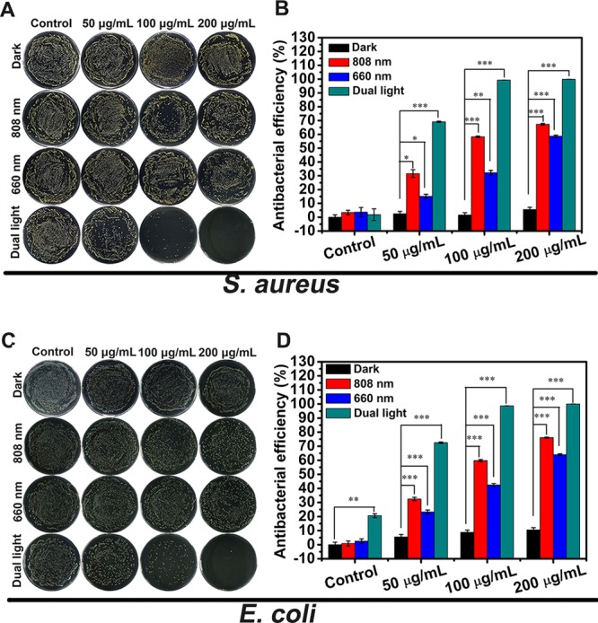
Photographs of bacterial colonies formed by (A) S. aureus and (C) E. coli and corresponding antibacterial rates of (B) S. aureus and (D) E. coli under the conditions of darkness and after exposure to 808 nm NIR, 660 nm red light, and dual light for 10 min (n = 3, *p < 0.05, **p < 0.01, ***p < 0.001).
To further study the antibacterial activity samples, the internal structures of the membrane damage of bacteria of S. aureus and E. coli are observed by TEM (Figure S22A–D). When under dark conditions, S. aureus and E. coli have smooth walls or membranes and an intracellular matrix that are integral. However, after 10 min of exposure to dual light, the cell walls of S. aureus and E. coli degenerated and ruptured, creating intracellular cytoplasmic efflux (red arrows indicate leaked proteins and lysed bacterial membranes). The BCA experiment further demonstrates the superiority of dual illumination by measuring the protein effluxes of S. aureus (Figure S22E) and E. coli (Figure S22F) under different conditions (light and dark). These results indicate that, under dual light illumination, the material exhibits good PTT and PDT effects; PTT changes the osmosis of bacterial membranes and reduces bacteria activity, while ROS-mediated oxidative stress impairs bacterial metabolism, and the membrane structure eventually leads to cell death.15
In Vitro Toxicity Assays
The in vitro cytotoxicity of the synthesized material is tested through MTT and cell fluorescence staining detection. PBS (control group), PB@MOF (50, 100, 200 μg mL–1), PB (100 μg mL–1), MOF (100 μg mL–1), and NIH-3T3 cells are cocultured for 1 day in an incubator at 37 °C. According to Figure 6A, the pure MOF has essentially no cytotoxicity, probably because zirconium is a biocompatible metal ion. However, PB has low cytotoxicity, with a cell viability of 84%. The toxicity of PB@MOF increases with the concentration increasing, but the survival rate of 200 μg mL–1 is still 83%. Figure S23 shows, at 37 °C, the cumulative concentration of Zr ions and Fe ions released from the PB@MOF in the PBS. The samples show continuous ion release. The reason for the good biocompatibility of materials may be because the zirconium ions and iron ions released from the MOF are nontoxic.50 To investigate the effects of light on cells, we performed a light MTT experiment. According to Figure 6B, the toxicity of the material is increased compared to the dark MTT, which may be because the active oxygen and heat generated by the material under illumination destroy the cells, but overall, even under the most cytotoxic concentration (200 μg mL–1), the material still has 53% of the living cells after illumination, indicating that the material can be used in clinical trials. To more intuitively evaluate the biocompatibility of materials, cell fluorescence is performed. Contrasted to the control group, the liveness of cells in the PB group is low, and it is not spreadable (Figure 6C). In contrast, the cell spreading is facilitated in the MOF group. As the concentration of PB@MOF increases, the activity of the cells is reduced, but there is still a good spread, indicating that the toxicity of the material is not large. Both fluorescent staining and MTT assays show that the materials have no negative effect for the cell, demonstrating good biocompatibility.
Figure 6.

(A) MTT assay of cell viability and (B) corresponding MTT assay of cell viability via different light treatments for 10 min. (C) Fluorescent images of cells after cultivating with different materials (control, PB, MOF, PB@MOF; scar bar, 50 μm; n = 3, *p < 0.05, **p < 0.01, ***p < 0.001).
In Vitro Animal Experiment
To detect the PDT and PTT synergistic antibacterial effects to facilitate extracorporeal wound healing, a 20 μL S. aureus (1 × 10⁸ CFU mL–1) solution is appended to the round wounds. Then, a 10 μL solution [PB@MOF (100 μg mL–1) or PBS (pH = 7.4)] is appended to the wound, and then, the wound was exposed to dual illumination for 10 min. Figure 7a demonstrates the wound healing process on different days. In contrast to the control and 3 M groups, after 4, 8, and 14 days of treatment, the best wound healing rate is obtained in the dual light illumination group; the wound is healed entirely at 14 days. Figure S24 shows the quantitative change in the wound area over time. The 3 M and dual light groups are better than the control group at 4, 8, and 14 days, but the dual light group is better than the 3 M group. This confirms that PDT and PTT synergistic antibacterial effects have a good promoting effect on wound healing. The wound treated differently is stained with Giemsa and hematoxylin and eosin (H&E) and photographed. The wound stained by Giemsa on the second day is demonstrated in Figure S25. High-magnification pictures display live bacteria in the injured tissue (red arrow). More germs are found in the control group, while the bacteria in the 3 M group are significantly fewer in number than in the control group. In contrast, much fewer bacteria are observed in the group irradiated with dual light than in the 3 M group. Figure 7B shows pictures of the three groups stained by H&E at different points in time (2, 4, 8, and 14 days). After 2, 4, and 8 days, vast inflammatory cells (neutrophils) appeared in the control group, and some inflammatory cells (red arrows) are noticed in the 3 M group. However, inflammatory cells are few in the dual illumination group. For the experimental group and 3 M groups, when it is at 14 days, the inflammatory cells in the wound are very rare. The results of Giemsa and H&E staining can demonstrate that PDT and PTT have excellent synergistic antibacterial effects and can promote wound healing. The effect of microscopic treatment in vivo is determined by routine blood analysis (Figure S26). The parameters of neutrophils and white blood cells (WBCs) are all within normal range. The histological analyses of the main organs (heart, liver, spleen, lung, and kidney) display no unusual phenomenon or injuries for 14 days of therapy, indicating that PB@MOF is safe in vivo.
Figure 7.

In vivo antibacterial experiments and wound healing. (A) Photographs of a wound in the group of control, 3 M, and PB@MOF at different points of 0, 2, 8, and 14 days. (B) Staining the histological pictures of the wounds after disposing with control, 3 M, and PB@MOF at different points of 0, 2, 8, and 14 days with H&E. Scar bars are 50 μm.
Conclusion
In summary, a dual metal organic framework (PB@MOF) with both photothermal and photodynamic properties has been successfully prepared. This material has a poor antibacterial effect under single illumination (808 nm NIR or 660 nm red light) for 10 min. However, its antibacterial effect has been greatly improved once it is irradiated with dual light for 10 min. The antibacterial rates to S. aureus and E. coli are 99.31% and 98.68%, respectively, demonstrating that this material exhibits a good antibacterial effect through photothermal and photodynamic synergistic action.
Acknowledgments
This work is jointly supported by the National Natural Science Foundation of China, 51671081, 51871162, and 51801056, the National Key Research and Development Program of China 2016YFC1100600 (subproject 2016YFC1100604), and Natural Science Fund of Hubei Province, 2018CFA064.
Supporting Information Available
The Supporting Information is available free of charge on the ACS Publications website at DOI: 10.1021/acscentsci.9b00639.
Additional figures including basic morphology and structure characterization, time-resolved PL spectra, Tauc plot, 1O2 detection, photothermal effect test, antibacterial experiment, live/dead staining, Zr and Fe ion amounts, and in vivo evaluation (PDF)
The authors declare no competing financial interest.
Supplementary Material
References
- Surdel M. C.; Horvath D. J.; Lojek L. J.; Fullen A. R.; Simpson J.; Dutter B. F.; Salleng K. J.; Ford J. B.; Jenkins J. L.; Nagarajan R.; Teixeira P. L.; Albertolle M.; Georgiev I. S.; Jansen E. D.; Sulikowski G. A.; Lacy D. B.; Dailey H. A.; Skaar E. P. Antibacterial photosensitization through activation of coproporphyrinogen oxidase. Proc. Natl. Acad. Sci. U. S. A. 2017, 114, 6652–6659. 10.1073/pnas.1700469114. [DOI] [PMC free article] [PubMed] [Google Scholar]
- Grzybowski J.; Janiak M. K.; Oidak E.; Lasocki K.; Wrembel-Wargocka J.; Cheda A.; Antos-Bielska M.; Pojda Z. New cytokine dressings. II. Stimulation of oxidative burst in leucocytes in vitro and reduction of viable bacteria within an infected wound. Int. J. Pharm. 1999, 184, 179–187. 10.1016/S0378-5173(99)00064-2. [DOI] [PubMed] [Google Scholar]
- Zhang L.; Guerrero-Juarez C. F.; Hata T.; Bapat S. P.; Ramos R.; Plikus M. V.; Gallo R. L. Dermal adipocytes protect against invasive Staphylococcus aureus skin infection. Science 2015, 347, 67. 10.1126/science.1260972. [DOI] [PMC free article] [PubMed] [Google Scholar]
- Fukuda S.; Toh H.; Hase K.; Oshima K.; Nakanishi Y.; Yoshimura K.; Tobe T.; Clarke J. M.; Topping D. L.; Suzuki T.; Taylor T. D.; Itoh K.; Kikuchi J.; Morita H.; Hattori M.; Ohno H. Bifidobacteria can protect from enteropathogenic infection through production of acetate. Nature 2011, 469, 543–547. 10.1038/nature09646. [DOI] [PubMed] [Google Scholar]
- Luo X.; Qian L.; Xiao Y.; Tang Y.; Zhao Y.; Wang X.; Gu L.; Lei Z.; Bao J.; Wu J.; He T.; Hu F.; Zheng J.; Li H.; Zhu W.; Shao L.; Dong X.; Chen D.; Qian X.; Yang Y. A diversity-oriented rhodamine library for wide-spectrum bactericidal agents with low inducible resistance against resistant pathogens. Nat. Commun. 2019, 10, 258. 10.1038/s41467-018-08241-3. [DOI] [PMC free article] [PubMed] [Google Scholar]
- Peng B.; Zhang X.; Aarts D. G. A. L.; Dullens R. P. A. Superparamagnetic nickel colloidal nanocrystal clusters with antibacterial activity and bacteria binding ability. Nat. Nanotechnol. 2018, 13, 478–482. 10.1038/s41565-018-0108-0. [DOI] [PubMed] [Google Scholar]
- Vera D. M. A.; Haynes M. H.; Ball A. R.; Dai T.; Astrakas C.; Kelso M. J.; Hamblin M. R.; Tegos G. P. Strategies to potentiate antimicrobial photoinactivation by overcoming resistant phenotypes. Photochem. Photobiol. 2012, 88, 499–511. 10.1111/j.1751-1097.2012.01087.x. [DOI] [PMC free article] [PubMed] [Google Scholar]
- Liu G.; Zou J.; Tang Q.; Yang X.; Zhang Y. W.; Zhang Q.; Huang W.; Chen P.; Shao J.; Dong X. Surface modified Ti3C2 MXene nanosheets for tumor targeting photothermal/photodynamic/chemo synergistic therapy. ACS Appl. Mater. Interfaces 2017, 9, 40077–40086. 10.1021/acsami.7b13421. [DOI] [PubMed] [Google Scholar]
- Wang S.; Li K.; Chen Y.; Chen H.; Ma M.; Feng J.; Zhao Q.; Shi J. Biocompatible PEGylated MoS2 nanosheets: controllable bottom-up synthesis and highly efficient photothermal regression of tumor. Biomaterials 2015, 39, 206–217. 10.1016/j.biomaterials.2014.11.009. [DOI] [PubMed] [Google Scholar]
- Maisch T.; Baier J.; Franz B.; Maier M.; Landthaler M.; Szeimies R.-M.; Bäumler W. The role of singlet oxygen and oxygen concentration in photodynamic inactivation of bacteria. Proc. Natl. Acad. Sci. U. S. A. 2007, 104, 7223–7228. 10.1073/pnas.0611328104. [DOI] [PMC free article] [PubMed] [Google Scholar]
- Tang Q.; Xiao W.; Huang C.; Si W.; Shao J.; Huang W.; Chen P.; Zhang Q.; Dong X. pH-triggered and enhanced simultaneous photodynamic and photothermal therapy guided by photoacoustic and photothermal imaging. Chem. Mater. 2017, 29, 5216–5224. 10.1021/acs.chemmater.7b01075. [DOI] [Google Scholar]
- Liang P.; Wang Y.; Wang P.; Zou J.; Xu H.; Zhang Y.; Si W.; Dong X. Triphenylamine flanked furan-diketopyrrolopyrrole for multiimaging guided photothermal/photodynamic cancer therapy. Nanoscale 2017, 9, 18890–18896. 10.1039/C7NR07204J. [DOI] [PubMed] [Google Scholar]
- Kempf V. A. J.; Lebiedziejewski M.; Alitalo K.; Wälzlein J. H.; Ehehalt U.; Fiebig J.; Huber S.; Schütt B.; Sander C. A.; Müller S.; Grassl G.; Yazdi A. S.; Brehm B.; Autenrieth I. B. Activation of hypoxia-inducible factor-1 in bacillary angiomatosis evidence for a role of hypoxia-inducible factor-1 in bacterial infections. Circulation 2005, 111, 1054–1062. 10.1161/01.CIR.0000155608.07691.B7. [DOI] [PubMed] [Google Scholar]
- Borovička J.; Metheringham W. J.; Madden L. A.; Walton C. D.; Stoyanov S. D.; Paunov V. N. Photothermal colloid antibodies for shape-selective recognition and killing of microorganisms. J. Am. Chem. Soc. 2013, 135, 5282–5285. 10.1021/ja400781f. [DOI] [PubMed] [Google Scholar]
- Li Y.; Liu X.; Tan L.; Cui Z.; Yang X.; Zheng Y.; Yeung K. W. K.; Chu P. K.; Wu S. Rapid sterilization and accelerated wound healing using Zn2+ and graphene oxide modified g-C3N4 under dual light irradiation. Adv. Funct. Mater. 2018, 28, 1800299. 10.1002/adfm.201800299. [DOI] [Google Scholar]
- Horcajada P.; Gref R.; Baati T.; Allan P. K.; Maurin G.; Couvreur P.; Ferey G.; Morris R. E.; Serre C. Metal-organic frameworks in biomedicine. Chem. Rev. 2012, 112, 1232–1268. 10.1021/cr200256v. [DOI] [PubMed] [Google Scholar]
- Jiang H.; Liu X. C.; Wu Y.; Shu Y.; Gong X.; Ke F. S.; Deng H. Metal-organic frameworks for high charge-discharge rate in lithium-sulfur battery. Angew. Chem., Int. Ed. 2018, 57, 3916–3921. 10.1002/anie.201712872. [DOI] [PubMed] [Google Scholar]
- Wu C. D.; Zhao M. Incorporation of molecular catalysts in metal–organic frameworks for highly efficient heterogeneous catalysis. Adv. Mater. 2017, 29, 1605446. 10.1002/adma.201605446. [DOI] [PubMed] [Google Scholar]
- Dong Z.; Sun Y.; Chu J.; Zhang X.; Deng H. Multivariate metal–organic frameworks for dialing-in the binding and programming the release of drug molecules. J. Am. Chem. Soc. 2017, 139, 14209–14216. 10.1021/jacs.7b07392. [DOI] [PubMed] [Google Scholar]
- Li Y.; Tang J.; He L.; Liu Y.; Liu Y.; Chen C.; Tang Z. Core–shell upconversion nanoparticle@metal–organic framework nanoprobes for luminescent/magnetic dual-mode targeted imaging. Adv. Mater. 2015, 27, 4075–4080. 10.1002/adma.201501779. [DOI] [PubMed] [Google Scholar]
- Yang Y.; Liu J.; Liang C.; Feng L.; Fu T.; Dong Z.; Chao Y.; Li Y.; Lu G.; Chen M.; Liu Z. Nanoscale metal–organic particles with rapid clearance for magnetic resonance imaging guided photothermal therapy. ACS Nano 2016, 10, 2774–2781. 10.1021/acsnano.5b07882. [DOI] [PubMed] [Google Scholar]
- Zeng J. Y.; Zou M. Z.; Zhang M.; Wang X. S.; Zeng X.; Cong H.; Zhang X. Z. Π-extended benzoporphyrin-based metal-organic framework for inhibition of tumor metastasis. ACS Nano 2018, 12, 4630–4640. 10.1021/acsnano.8b01186. [DOI] [PubMed] [Google Scholar]
- He C.; Liu D.; Lin W. Nanomedicine applications of hybrid nanomaterials built from metal–ligand coordination bonds: nanoscale metal–organic frameworks and nanoscale coordination polymers. Chem. Rev. 2015, 115, 11079–11108. 10.1021/acs.chemrev.5b00125. [DOI] [PubMed] [Google Scholar]
- Lu K.; He C.; Lin W. Nanoscale metal–organic framework for highly effective photodynamic therapy of resistant head and neck cancer. J. Am. Chem. Soc. 2014, 136, 16712–16715. 10.1021/ja508679h. [DOI] [PMC free article] [PubMed] [Google Scholar]
- Liu J.; Yang Y.; Zhu W.; Yi X.; Dong Z.; Xu X.; Chen M.; Yang K.; Lu G.; Jiang L.; Liu Z. Nanoscale metalorganic frameworks for combined photodynamic & radiation therapy in cancer treatment. Biomaterials 2016, 97, 1–9. 10.1016/j.biomaterials.2016.04.034. [DOI] [PubMed] [Google Scholar]
- Wang D.; Niu L.; Qiao Z. Y.; Cheng D. B.; Wang J.; Zhong Y.; Bai F.; Wang H.; Fan H. Synthesis of self-assembled porphyrin nanoparticle photosensitizers. ACS Nano 2018, 12, 3796–3803. 10.1021/acsnano.8b01010. [DOI] [PubMed] [Google Scholar]
- Park J.; Jiang Q.; Feng D.; Mao L.; Zhou H. C. Size-controlled synthesis of porphyrinic metal–organic framework and functionalization for targeted photodynamic therapy. J. Am. Chem. Soc. 2016, 138, 3518–3525. 10.1021/jacs.6b00007. [DOI] [PubMed] [Google Scholar]
- Yoon S. M.; Park J. H.; Grzybowski B. A. Large-Area, freestanding MOF films of planar, curvilinear, or micropatterned topographies. Angew. Chem., Int. Ed. 2017, 56, 127–132. 10.1002/anie.201607927. [DOI] [PubMed] [Google Scholar]
- Wang D.; Zhou J.; Chen R.; Shi R.; Zhao G.; Xia G.; Li R.; Liu Z.; Tian J.; Wang H.; Guo Z.; Wang H.; Chen Q. Controllable synthesis of dual-MOFs nanostructures for pH-responsive artemisinin delivery, magnetic resonance and optical dual-model imaging-guided chemo/photothermal combinational cancer therapy. Biomaterials 2016, 100, 27–40. 10.1016/j.biomaterials.2016.05.027. [DOI] [PubMed] [Google Scholar]
- Cliffe M. J.; Wan W.; Zou X.; Chater P. A.; Kleppe A. K.; Tucker M. G.; Wilhelm H.; Funnell N. P.; Coudert F. X.; Goodwin A. L. Correlated defect nanoregions in a metal–organic framework. Nat. Commun. 2014, 5, 4176. 10.1038/ncomms5176. [DOI] [PMC free article] [PubMed] [Google Scholar]
- Wu H.; Chua Y. S.; Krungleviciute V.; Tyagi M.; Chen P.; Yildirim T.; Zhou W. Unusual and highly tunable missing-linker defects in zirconium metal–organic framework UiO-66 and their important effects on gas adsorption. J. Am. Chem. Soc. 2013, 135, 10525–10532. 10.1021/ja404514r. [DOI] [PubMed] [Google Scholar]
- Sun Y.; Sun L.; Feng D.; Zhou H. C. An in situ one-pot synthetic approach towards multivariate zirconium MOFs. Angew. Chem., Int. Ed. 2016, 55, 6471–6475. 10.1002/anie.201602274. [DOI] [PubMed] [Google Scholar]
- Park J.; Jiang Q.; Feng D.; Zhou H. C. Controlled generation of singlet oxygen in living cells with tunable ratios of the photochromic switch in metal–organic frameworks. Angew. Chem., Int. Ed. 2016, 55, 7188–7193. 10.1002/anie.201602417. [DOI] [PubMed] [Google Scholar]
- Zhang X.; Yang Y.; Huang W.; Yang Y.; Wang Y.; He C.; Liu N.; Wu M.; Tang L. g-C3N4/UiO-66 nanohybrids with enhanced photocatalytic activities for the oxidation of dye under visible light irradiation. Mater. Res. Bull. 2018, 99, 349–358. 10.1016/j.materresbull.2017.11.028. [DOI] [Google Scholar]
- Zeng J. Y.; Zhang M. K.; Peng M. Y.; Gong D.; Zhang X. Z. Porphyrinic metal–organic frameworks coated gold nanorods as a versatile nanoplatform for combined photodynamic/photothermal/chemotherapy of tumor. Adv. Funct. Mater. 2018, 28, 1705451. 10.1002/adfm.201705451. [DOI] [Google Scholar]
- Li Y.; Di Z.; Gao J.; Cheng P.; Di C.; Zhang G.; Liu B.; Shi X.; Sun L. D.; Li L.; Yan C. H. Heterodimers made of upconversion nanoparticles and metal–organic frameworks. J. Am. Chem. Soc. 2017, 139, 13804–13810. 10.1021/jacs.7b07302. [DOI] [PubMed] [Google Scholar]
- Yang C.; Qin J.; Xue Z.; Ma M.; Zhang X.; Liu R. Rational design of carbon-doped TiO2 modified g-C3N4 via in-situ heat treatment for drastically improved photocatalytic hydrogen with excellent photostability. Nano Energy 2017, 41, 1–9. 10.1016/j.nanoen.2017.09.012. [DOI] [Google Scholar]
- Wang M.; Cai L.; Wang Y.; Zhou F.; Xu K.; Tao X.; Chai Y. Graphene-draped semiconductors for enhanced photocorrosion resistance and photocatalytic properties. J. Am. Chem. Soc. 2017, 139, 4144–4151. 10.1021/jacs.7b00341. [DOI] [PubMed] [Google Scholar]
- Dai Y.; Wang X.; Peng W.; Xu C.; Wu C.; Dong K.; Liu R.; Wang Z. L. Self-powered Si/CdS flexible photodetector with broadband response from 325 to 1550 nm based on pyro-phototronic effect: an approach for photosensing below bandgap energy. Adv. Mater. 2018, 30, 1705893. 10.1002/adma.201705893. [DOI] [PubMed] [Google Scholar]
- Xu Y.; Wang S.; Yang J.; Han B.; Nie R.; Wang J.; Wang J.; Jing H. In-situ grown nanocrystal TiO2 on 2D Ti3C2 nanosheets for artificial photosynthesis of chemical fuels. Nano Energy 2018, 51, 442–450. 10.1016/j.nanoen.2018.06.086. [DOI] [Google Scholar]
- Zou Y.; Yang B.; Liu Y.; Ren Y.; Ma J.; Zhou X.; Cheng X.; Deng Y. Controllable interface-induced co-Assembly toward highly ordered mesoporous Pt@TiO2/g-C3N4 heterojunctions with enhanced photocatalytic performance. Adv. Funct. Mater. 2018, 28, 1806214. 10.1002/adfm.201806214. [DOI] [Google Scholar]
- Shi L.; Wang T.; Zhang H.; Chang K.; Ye J. Electrostatic self-assembly of nanosized carbon nitride nanosheet onto a zirconium metal–organic framework for enhanced photocatalytic CO2 reduction. Adv. Funct. Mater. 2015, 25, 5360–5367. 10.1002/adfm.201502253. [DOI] [Google Scholar]
- Yu X.; Zhao Z.; Sun D.; Ren N.; Yu J.; Yang R.; Liu H. Microwave-assisted hydrothermal synthesis of Sn3O4 nanosheet/rGO planar heterostructure for efficient photocatalytic hydrogen generation. Appl. Catal., B 2018, 227, 470–476. 10.1016/j.apcatb.2018.01.055. [DOI] [Google Scholar]
- Zhang Z.; Jiang X.; Liu B.; Guo L.; Lu N.; Wang L.; Huang J.; Liu K.; Dong B. IR-driven ultrafast transfer of plasmonic hot electrons in nonmetallic branched heterostructures for enhanced H2 generation. Adv. Mater. 2018, 30, 1705221. 10.1002/adma.201705221. [DOI] [PubMed] [Google Scholar]
- Liu D.; Wang J.; Bai X.; Zong R.; Zhu Y. Self-assembled PDINH supramolecular system for photocatalysis under visible light. Adv. Mater. 2016, 28, 7284–7290. 10.1002/adma.201601168. [DOI] [PubMed] [Google Scholar]
- Arnett D. C.; Vöhringer P.; Scherer N. F. Excitation dephasing, product formation, and vibrational coherence in an intervalence charge-transfer reaction. J. Am. Chem. Soc. 1995, 117, 12262–12272. 10.1021/ja00154a028. [DOI] [Google Scholar]
- Wojdeł J. C. First principles calculations on the influence of water-filled cavities on the electronic structure of prussian blue. J. Mol. Model. 2009, 15, 567–572. 10.1007/s00894-008-0425-6. [DOI] [PubMed] [Google Scholar]
- Chen L.; Bai H.; Xu J. F.; Wang S.; Zhang X. Supramolecular porphyrin photosensitizers: controllable disguise and photoinduced activation of antibacterial behavior. ACS Appl. Mater. Interfaces 2017, 9, 13950–13957. 10.1021/acsami.7b02611. [DOI] [PubMed] [Google Scholar]
- Tan L.; Li J.; Liu X.; Cui Z.; Yang X.; Zhu S.; Li Z.; Yuan X.; Zheng Y.; Yeung K. W. K.; Pan H.; Wang X.; Wu S. Rapid biofilm eradication on bone implants using red phosphorus and near-infrared light. Adv. Mater. 2018, 30, 1801808. 10.1002/adma.201801808. [DOI] [PubMed] [Google Scholar]
- Tan L. L.; Li H.; Zhou Y.; Zhang Y.; Feng X.; Wang B.; Yang Y. W. Zn2+-triggered drug release from biocompatible zirconium MOFs equipped with supramolecular gates. Small 2015, 11, 3807–3813. 10.1002/smll.201500155. [DOI] [PubMed] [Google Scholar]
Associated Data
This section collects any data citations, data availability statements, or supplementary materials included in this article.