Abstract
Two-scale CFD modeling is used to design and optimize a novel endovascular filtration device for removing toxins from flowing blood. The Chemofilter is temporarily deployed in the venous side of a tumor during the intra-arterial chemotherapy in order to filter excessive chemotherapy drugs such as Doxorubicin from the blood stream. The device chemically binds selective drugs to its surface thus filtering them from blood, after they have had the effect on the tumor and before they reach the heart and other organs. The Chemofilter consists of a porous membrane made of microscale architected materials and is installed on a structure similar to an embolic protection device. Simulations resolving the microscale structure of the device were carried out to determine the permeability of the microcell membrane. The resulting permeability coefficients were then used for macroscale simulations of the flow through the device modeled as a porous material. The microscale simulations indicate that greater number of microcell layers and smaller microcell size result in increased pressure drop across the membrane, while providing larger surface area for drug binding. In the macroscale simulations, the study of idealized prototypes show that the pressure drop can be reduced by increasing the membrane’s tip angle and by decreasing the number of membrane’s sectors. Such design, however, can conversely affect the overall drug binding. By decreasing the concentration of toxins in the cardiovascular system, the drug dosage can be increased while side effects are reduced, thus improving the effectiveness of treatment.
Keywords: Intra-arterial chemotherapy, Multiscale modeling, Computational fluid dynamics, Hemodynamics, Porous membrane, Architected material, Chemofiltration
1. Introduction
Hepatocellular carcinoma (HCC), the primary liver cancer, is the third cause of cancer death worldwide (Altekruse 2009). In cases that are not amenable to surgery, intra-arterial chemotherapy (IAC) is the most common HCC treatment (Roche et al. 2003; Stuart 2003). In the IAC procedure, localization of the chemotherapy agents allows targeted drug delivery to the tumor, as opposed to the systemic intravenous chemotherapy. However, studies show that up to 50–70% of the IAC drugs pass through the liver, contributing to the accumulation of toxicity in healthy organs which leads to side effects such as irreversible heart failure (Aboian et al. 2016; Alexander et al. 2011, 2012; Lewis et al. 2006).
To reduce the side effects of the IAC procedure, previous studies have proposed the application of DC and LC Beads™(BTG, UK) to slowly release Doxorubicin, and Hepatic CHEMOSAT™ delivery system (Delcath Systems, NY) for extracorporeal filtration of the excessive drugs that pass through the liver. The Hepatic CHEMOSAT™ platform creates significant blood flow disturbance in addition to high cost and technical challenges, which has led to safety concerns by the FDA (Dougherty et al. 1997; Patel et al. 2014). Therefore, a novel Chemofilter device was proposed for addressing the problem.
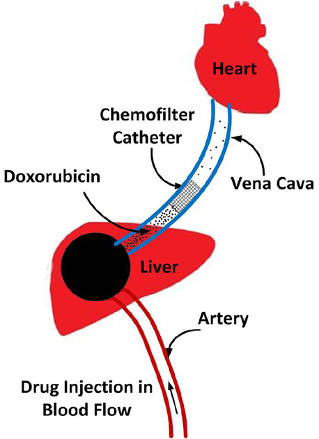
Chemofilter is a catheter-based endovascular filtration device that chemically binds selected drugs to its surface in order to purify blood from toxins. In the IAC procedure, embolic and chemotherapeutic agents, e.g., a mixture of Doxorubicin (Dox) and Cisplatin, are hand-injected into the hepatic artery for about 10 min. During this time, the Chemofilter would be temporarily deployed downstream of the tumor, in the hepatic vein or the inferior vena cava, in order to capture the excessive drug molecules after they have had their effect on the tumor and before they reach the heart and other organs (Fig. 1).
Fig. 1.
Schematics of IAC procedure and Chemofilter deployment in the hepatic vein
Two alternative materials are currently considered for chemical binding of the drugs to the Chemofilter: an ion-exchange resin and a DNA-loaded resin. Recent studies conducted on these materials confirmed excellent binding capabilities of both systems to Doxorubicin and Cisplatin, with the DNA Chemofilter exhibiting better binding kinetics overall (Aboian et al. 2016). While the drug binding mechanisms and efficiency of the Chemofilter have been the focus of the studies to date (Aboian et al. 2016; Chen et al. 2016; Fisher 2016; Kondapavulur et al. 2016; Patel et al. 2014), the flow dynamic performance of these devices has not yet been thoroughly investigated. It is imperative that the configuration and structure of the Chemofilter are designed and optimized to minimize flow obstruction and thrombosis while providing sufficient binding surface for the drug.
The deployment of the Chemofilter can significantly impact local hemodynamics. A stagnant or recirculating flow around the Chemofilter may increase the risk of blood clotting (Kroll et al. 1996; Lowe 2003; Ren et al. 2012). A computational study of partially occluded inferior vena cava (IVC) filters used for trapping thromboemboli suggested that large shear stresses may result in resumption of thrombotic-like behavior around the vein’s wall or the acceleration of thrombolysis (Ren et al. 2012; Singer et al. 2009; Singer and Wang 2011). Therefore, a thorough investigation of blood flow characteristics around the Chemofilter membrane is necessary.
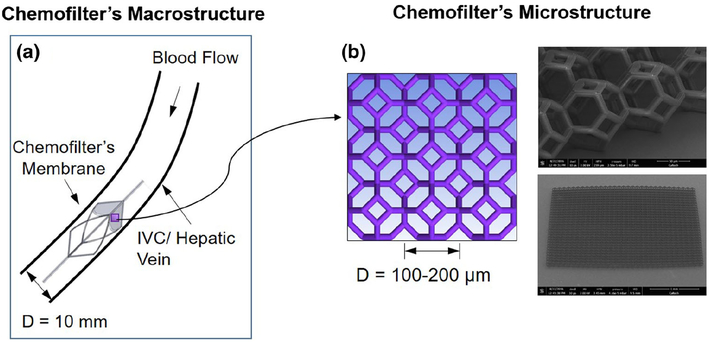
Current Chemofilter prototypes range from macroporous 2D membranes to mesh bags, which are difficult to manipulate and optimize to improve hemodynamic performance. Microscale architected materials present a possible alternative as they can be fabricated in any arbitrary size and shape. In this study, we assess the hemodynamic performance of a Chemofilter membrane manufactured from microscale architected materials. As shown in Fig. 2, the Chemofilter consists of a matrix of microscale unit cells (microcells) that connect to each other in layers to form an umbrellashaped porous membrane. The membrane is installed on a self-expanding nitinol frame, which is placed in a catheter for deployment (Siewiorek and Finol 2010). The hemodynamic performance of the proposed device is evaluated with computational fluid dynamics (CFD) in order to optimize the design of the Chemofilter microstructure as well as the overall shape of the device.
Fig. 2.
Multiscale approach for modeling the Chemofilter a the schematic of the device deployed in the hepatic vein, b the schematic and SEM image of a matrix of microcells
2. Methods
In this study, various configurations of the prototype Chemofilter device are considered in order to evaluate their hemodynamic performance. The flow proximal to the deployed Chemofilter will be retarded, thus facilitating drug binding to the device. At the same time, reducing flow stagnation regions around the filter is crucial for preventing thrombus formation. Thus, the Chemofilter design should be aimed at providing sufficient surface for the chemical binding of the drugs, while minimizing flow obstruction. Since the vein diameter, approximately 10 mm, is 2 orders of magnitude larger than the size of a 100-micron microcell, a multiscale approach is used to model the flow through the Chemofilter. In this approach, the flow through a representative matrix of the microcells is resolved in order to determine the permeability of the lattice. The obtained values are then used to simulate the flow through the whole device modeled as a porous membrane. Darcy’s law is applied to calculate the porous characteristics of the membrane. By computing the pressure on both sides of the lattice comprising the Chemofilter’s membrane, the permeability tensor (m2) is calculated as:
| (1) |
where is the blood flux per unit area (m/s), μ is the blood viscosity, and P is the pressure gradient. The components of the permeability tensor were determined by carrying out CFD simulations for different orientation of the membrane relative to the flow, as characterized by the angle (α). Porosity is defined as the average volume of the pores divided by the total volume:
| (2) |
Idealized models of the Chemofilter and a representative segment of the microcell lattice were generated using SolidWorks (Dassault Systems) software. In designing these microcells, the following principles were used to enhance the fluid flow: (a) the microcells are tessellated in order to fill the space in 3D, (b) a hollow space within the microcell minimizes potential disruption of the flow, and (c) the surface area is high relative to the enclosed volume. With these three features in mind, an open cell tetrakaidecahedron was chosen as the initial unit cell candidate for this study.
2.1. CFD modeling approach
A multiscale modeling approach was used for the analysis of blood flow through the Chemofilter. In this approach, a detailed numerical simulation was carried out for the flow through a matrix of 2 × 2 microcells with periodic boundary conditions (BC) on the walls in order to determine the flow resistance of the whole membrane. The unstructured mesh with prism layers around the microtrusses was generated using ANSYSICEM software. In order to ensure that the mesh elements at the periodic boundaries are identical, one quarter of the domain was initially meshed and the volume mesh was then mirrored in both directions to provide conformity of elements on the walls. The simulations of blood flow through the microcell matrix were conducted to characterize the performance of the lattice with different microcell sizes (ranging from 100 to 200 μm), number of microcell layers (from 1 to 3), and different membrane orientations relative to the flow. Consequently, the porosity and permeability of the microcell matrix was obtained and the whole Chemofilter device was modeled as a porous membrane without resolving the individual cells. To ensure that the 2 × 2 microcell matrix could adequately represent the membrane, the results were compared with those obtained in simulation for a 4 × 4 microcell matrix. In addition, a mesh size sensitivity analysis was conducted to ensure sufficient resolution of the boundary layer formed around the microtrusses. Increasing the number of computational elements from 2 to 8 million (1 layer of 2 × 2 microcell matrix simulation) resulted in less than 10% change of the calculated pressure drop across the microcell lattice.
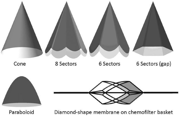
In the macroscale model, the idealized membrane was modeled as a canopy that fits the blood vessel’s cross section. Various configurations of the porous membrane resembled an umbrella, as shown in Fig. 3. In order to evaluate the flow for an umbrella-shaped device, the membranes with 6 and 8 sectors were modeled. The hemodynamic performance of the membranes with different opening angles (tip angle), thicknesses, and shapes were compared. A model where the umbrella sectors were extended all the way to the vessel wall, thus forming petal-shaped flat surface canopies, was compared to that with a gap formed between the triangular canopy sectors and the vessel. Once the flow through the umbrella-shaped membrane was characterized, a porous membrane installed on a supporting nitinol frame, analogous in shape to the RX Accunet embolic protection device (Abbott Labs), was modeled. In this configuration of the Chemofilter, the membrane covered the 4 diamond-shaped sectors of the structure (Fig. 3). The macroscale geometry was also meshed in ICEM CFD (ANSYS) software. A hybrid meshing was used to resolve the flow around the device by increasing the number of elements in proximity to the porous membrane, with a gradual increase of the element size farther away from the filter. The mesh density was adjusted in order to control the mesh growth size in the flow regions adjacent to the filter. In order to reduce computational time by using the symmetric geometry of the umbrella-shaped device, one sector of the membrane, i.e., one quarter of the domain, was modeled and symmetry boundary conditions were applied on the side walls.
Fig. 3.
Different configurations of the Chemofilter’s membrane. The membrane may consist of 1–3 layers of microcells with 100–300 μm diameter. The angle of idealized umbrella-shaped membrane varies between 22° and 60°
In the simulations of the whole device, the hepatic vein was modeled as a straight rigid tube with 10 mm diameter. The section of the tube proximal to the device was sufficiently long to ensure the flow becomes fully developed before reaching the Chemofilter. Blood was modeled as a Newtonian, homogeneous fluid with the constant density and dynamic viscosity of ρ = 1060 kg/m3 and μ = 0.0035 kg/m s, respectively. The Navier-Stokes equations were solved with a finite-volume solver, Fluent (ANSYS), using a coupled scheme for velocity-pressure coupling. Second-order and third-order MUSCL schemes were used for the pressure and momentum spatial discretizations, respectively. The flow was modeled as steady due to a negligible effect of the heart pulse in the hepatic vein, and the relatively low Reynolds number (Re = 300) ensured the flow remained laminar. The inlet velocity was set to 0.1 m/s and the outflow boundary condition was assigned to the outlet.
3. Results
The Chemofilter deployment results in a pressure drop across the porous membrane and formation of a flow disturbance region around the device. The CFD simulations conducted for different configurations of the Chemofilter’s membrane demonstrated the effect of device geometry on the resulting flow fields.
3.1. Microstructure model
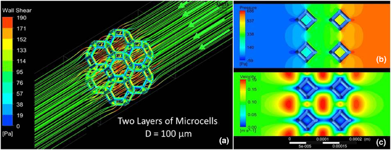
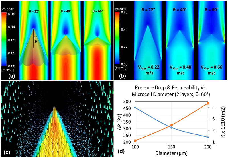
Figure 4 shows the flow through a segment of the lattice, characterized by the accelerated flow through the microcells and higher shear stress on the front face of the microtrusses. For a two-layer matrix of 2 × 2 microcells with 100 μm size, the pressure drop was about 600 Pa across the membrane. The comparison of the lattices made of 2 × 2 and 4 × 4 matrix showed a 3% difference in the pressure drop, with the higher value for the 2 × 2 matrix. Since the difference was negligible, the rest of the microscale simulations were carried out for the 2 × 2 matrix. The parametric studies were conducted to determine the dependence of the pressure drop across the membrane on the size and thickness of the lattice. The microcell diameter ranged between 100 and 200 μm, and the lattice consisted of 1, 2, and 3 layers of the cells. Figure 5 indicates that increasing the microcell size resulted in a smaller pressure drop for the same number of layers. Increasing the number of layers of identical size microcells resulted in increase in the pressure drop across the membrane.
Fig. 4.
a Flow streamlines and shear stress distribution for a 2 × 2 microcell matrix b pressure and c velocity contours calculated for the flow through two layers of 2 × 2 matrix with 100-μm microcells
Fig. 5.
Effect of the microcell size and number of layers on the pressure drop across the membrane
To calculate the permeability tensor, the simulations were run for various angles of the lattice with respect to the flow. Figure 6a shows the schematic of the Chemofilter, and Fig. 6b shows the flow as it approaches the lattice at an angle of α = 30°, but leaves it normal to the lattice surface. The results suggested an isotropic behavior of Chemofilter:
Fig. 6.
a Schematics of the Chemofilter geometry with an arbitrary angle α, b velocity vectors around the lattice with α =30°
The membrane’s porosity is ε=0.92 and permeability of the membrane is depicted in Fig. 7d.
Fig. 7.
Velocity contours for an umbrella-shaped Chemofilter with different tip angle θ a extended all the way to the wall b with a gap; c velocity vectors around the membrane’s tip for two layers of 100-μm cells; d the effect of microcell diameter on the overall membrane’s permeability and pressure drop
3.2. Macrostructure model
The umbrella-shaped membrane was considered as the primary Chemofilter geometry. Figure 3 demonstrates the schematics of various device configurations, including a membrane forming a cone, a membrane made of 6 or 8 sectors extending to the vessel wall, a membrane shaped out of 6 triangular sectors with a gap near the wall, the paraboloid, and a diamond-shape membrane installed on the nitinol frame structure.
Figure 7 demonstrates the effect of the tip angle on the flow through the membrane consisting of 8 petal-like sectors. The geometries with the angles of 22°, 40°, and 60° were modeled. The velocity contours in Fig. 7a show the formation of a high-velocity jet between the membrane and the vessel wall and a stagnant flow downstream of the membrane’s tip. A gap may form between the sectors of the membrane and the vessel wall either because of the non-circular shape of the sectors or because of the imperfect placement of the device. Figure 7b shows that the maximum velocity of the flow escaping the membrane through the gap increases for larger tip angles. Consequently, a greater fraction of the blood can bypass the Chemofilter. Figure 7d shows that the pressure drop decreases with increasing the microcell size, as the membrane’s permeability increases.
The hemodynamic performance of different membrane configurations is shown in Table 1. The pressure drop decreases if the number of the membrane sectors is reduced. For smaller tip angles, the pressure drop decreases, while the membrane area increases. The gap area and, consequently, the mass flow rate escaping through the gap for the 6-sector configuration is larger than that of the 8-sector one.
Table 1.
Comparison of hemodynamic performance of different membrane shapes (two layers of 100-μm microcells)
| Two layers of microcells (D = 100 (μm) | Membrane’s tip angle θ | Without gap | With gap | |||
|---|---|---|---|---|---|---|
| ΔP (Pa) | Area (m2) | ΔP (Pa) | Escaped blood flow | Surface area (gap/membrane) | ||
| Cone | 22° | 94 | 1.095 × 10⁻³ | - | - | - |
| 6 Sectors | 22° | 74 | 1.238 × 10⁻³ | 66 | 28% | 21% |
| 8 Sectors | 22° | 79 | 1.171 × 10⁻³ | 79 | 12% | 11% |
| 40° | 237 | 0.691 × 10⁻³ | 185 | 24% | 10% | |
| 60° | 455 | 0.497 × 10⁻³ | 293 | 36% | 10% | |
3.3. Chemofilter basket design
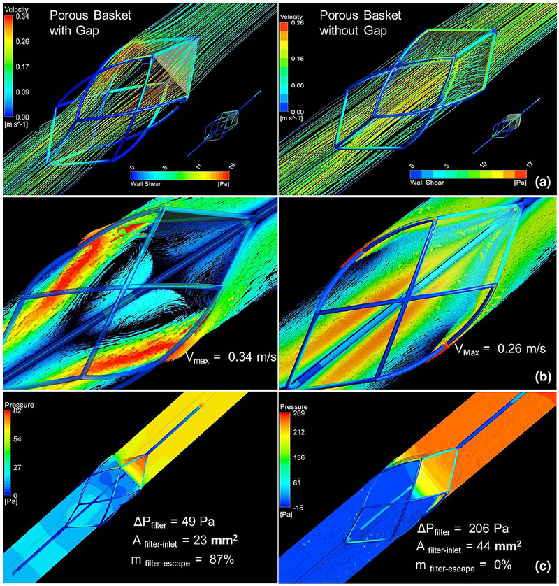
Figure 8 depicts the velocity vectors and pressure and shear contours obtained for the Chemofilter designed as an embolic protection device basket covered by a porous membrane. The lattice consisting of two layers of the 150-μm microcells, with the tip angle of 40°, and four sectors were chosen for the simulation of the membrane installed on the structure. The case where the sectors of the canopy have a flat triangular shape, thus causing a gap between the filter and the wall, is compared with the case where the membrane is extended to cover the gap. The blood escaping through the filter leads to a larger flow recirculation region with the maximum velocity of 0.34 m/s for the case with the gap compared to 0.26 m/s for the fully covered frame. The pressure drop across the triangular membrane decreases to about a quarter of that computed for the fully covered design, while the triangular membrane’s surface area is a half of the fully covered one.
Fig. 8.
a Flow streamlines passing through the Chemofilter and shear stress on the Chemofilter basket structure b velocity vectors and c pressure distribution on the mid-plane parallel to the flow
4. Discussion
Blood flow through the Chemofilter device is studied with multiscale CFD simulations that resolve the flow through a lattice of microcells as well as model the flow across the filter’s porous membrane. The non-Newtonian blood behavior was neglected because the size of the vessel is much larger than the size of red blood cells and the shear rates around the microtrusses are larger than 100 s−1 (Tu and Deville 1996). In the microscale models, the pressure drop is directly proportional to the number of the membrane’s layers while it is inversely proportional to the microcell size. For example, the pressure drop for the three layers of 150-μm microcells is about the same as that of the two layers of 100-μm microcells, while the overall thickness of the membrane is 2.25 times larger for the former. The larger microcell size allows an easy passage of blood cells through the membrane due to its lower resistance. However, more Dox particles are likely to escape through the filters with larger microcell size and smaller number of layers, which lowers the amount of drug bound to the filter.
Examining the lattice orientation relative to the flow, the components of the permeability tensor were calculated and the membrane porous structure was found to be isotropic. The isotropic behavior of the lattice is due to the symmetric geometry of microcells and their repeating arrangement in the lattice. The detailed view of the flow near the tip shown in Figs. 6 and 7c, confirms that filtered blood exits the membrane normal to its surface, regardless of the entrance angle.
By calculating the pressure drop across the lattice, the porous characteristics of the Chemofilter were determined and used to evaluate the design of the membrane’s overall shape. The optimal geometry would minimize the pressure drop and reduce flow disturbance, while maximizing the surface area and flow residence time around the membrane in order to facilitate drug absorption. Therefore, different geometries were considered to study the effectiveness of the device, while avoiding the risk of blood clotting.
The study of the idealized umbrella-shaped membrane (Figs. 3, 7) indicates that a lower number of the membrane’s sectors, acute tip angles, and larger microcell size result in decreased pressure drop. However, chemical binding may be negatively affected by the latter parameters. The greater pressure drop across the membrane with larger number of sectors is due to the increase in the overall membrane surface area, as well as the discontinuity of the geometry at the intersection of sector’s canopy. The membrane with smaller tip angle causes less obstruction to the flow as it reaches the filter, resulting in lower pressure drop.
The design of a Chemofilter basket porous membrane was guided by the results obtained from studying the idealized umbrella-shaped prototypes. A four-sector membrane with the tip angle of 40° is installed on the nitinol struts forming the basket. The lattice has two layers of 150-μm microcells to provide relatively large contact area and low resistance to the flow. The fully developed flow, upon reaching the filter, uniformly exits the filter’s membrane normal to its surface. On the downstream side of the Chemofilter, the high-velocity jet is formed closer to the vessel wall, while a stagnant area is developed around the tip of the device due to the sharp angle of the membrane. The gap amplifies the jet velocity, as it provides a low resistance passage where the flow can escape unfiltered. The overall configuration of the device allows a moderate pressure drop and flow separation region. The results show that a gap in the Chemofilter basket design results in 87% of flow bypassing the filter, besides reducing the surface area. Therefore, the extended membrane’s canopy, which provides both mechanical strength and larger contact area, is preferred in this design. The curved extending part of the membrane forms a narrow space between the membrane and the wall, where the maximum velocity is found in the domain.
Blood flow through the flat umbrella-shaped filter was also compared with that of a paraboloid-shaped prototype to examine the membrane’s tip effect (see Fig. 3). For the paraboloid membrane, the sharp tip that caused flow disturbance for the umbrella design was avoided. By allowing a smooth transition between the high-velocity jet and mainstream flow, the area of stagnant flow behind the tip was reduced.
4.1. Limitations and future work
The slow flow through a porous membrane as well as in the stagnant regions downstream of the membrane may result in thrombus deposition. Since the Chemofilter is temporarily deployed during a 30–60-min chemotherapy session, the risk of thrombus formation can be minimized by administering a high dosage of heparin during the procedure.
One of the limitations of this study is the assumption of a rigid vessel wall, as the vein’s compliance may cause a gap near the edges of the Chemodilter, thus leading to a leakage of unfiltered blood at the periphery of the device. In addition, the apposition of the device can be imperfect, also resulting in a leakage of Dox through the gaps between the device membrane and the vessel.
Computational modeling of the Chemofilter is used for optimizing the device’s configuration and guiding the design of in vitro experiments and animal studies. The clinicians still debate whether the device will be deployed in the hepatic vein or IVC. Therefore, approximate numbers for the vein’s diameter and average velocity, suggested by clinicians, were chosen, matching the order of magnitude of the in vivo parameters. Since the study is evaluating the relative advantages of the alternative designs, the results are useful as long as the Reynolds number and flow conditions remain the same across the CFD simulations.
This paper presents an initial study that aims at developing a two-scale CFD model of the Chemofilter device. The model will be expanded to include chemical binding of the drugs to the membrane’s surface. The multiscale approach will be applied to first evaluate the drug binding to the individual microcells and consequently determine the change of the drug concentration for the flow through the porous membrane. The effect of the membrane’s elasticity will also be assessed in the future analysis. The Chemofilter design can benefit from increasing surface area which provides more binding sites. Using the architected material porous membrane allows to increase the surface area of the device as well as to enhance flow mixing. In addition, a lower Peclet number, defined as the ratio of the diffusion and advection timescales, can improve the filtration efficiency by providing sufficient time for the Dox particles to bind to the filter’s surface. The optimum design of the Chemofilter will therefore provide sufficient surface area and reaction time for the Dox binding.
5. Conclusion
The multiscale CFD simulations were used to evaluate hemodynamic performance of the Chemofilter membrane. The size of the microcells composing the porous membrane should allow for unobstructed passage of blood components, while it should be small enough to ensure sufficient adsorption of toxins and prevent their escape through the pores. A larger number of the microcell layers can provide adequate residence time and drug binding sites for filtration. The more acute tip angle of the membrane also results in a larger contact area for drug binding. However, the sharp tip angle should be avoided to reduce flow separation downstream of the filter. In general, a larger area of the filter causes more resistance to the flow, which consequently leads to larger pressure drop. A gap between the device and the vein’s wall reduces the efficiency of the filtration. Thus, extending the membrane’s canopy to cover more area of the Chemofilter frame structure will reduce the gap, while providing mechanical strength and larger surface area.
Acknowledgements
The Authors would like to acknowledge Daryl Yee and Dr. Julia Greer for providing the geometry of the microtrusses and microcells used in this study. We also acknowledge Teri Moore for coordinating the study and data exchange. The work presented was supported by NIH grants 1R01CA194533 (Steven Hetts, PI; UCSF). A patent underlying the Chemofilter technology was licensed to Chemofilter, Inc, by the University of California; that license was subsequently incorporated in the acquisition of Chemofilter, Inc by Penumbra, Inc (Alameda, California). Chemofilter is a trademark of Penumbra, Inc.
Footnotes
Publisher’s Note Publisher’s Note Springer Nature remains neutral with regard to jurisdictional claims in published maps and institutional affiliations.
Conflict of interest The authors declare that they have no conflict of interest.
References
- Aboian MS, Yu JF, Gautam A, Sze CH, Yang JK, Chan J, Lillaney PV, Jordan CD, Oh HJ, Wilson DM, Patel AS, Wilson MW, Hetts SW (2016) In vitro clearance of doxorubicin with a DNA-based filtration device designed for intravascular use with intra-arterial chemotherapy. Biomed Microdevices 18(6):98. [DOI] [PMC free article] [PubMed] [Google Scholar]
- Alexander CM, Maye MM, Dabrowiak JC (2011) DNA-capped nanoparticles designed for doxorubicin drug delivery. Chem Commun 47(12):3418–3420 [DOI] [PubMed] [Google Scholar]
- Alexander CM, Dabrowiak JC, Maye MM (2012) Investigation of the drug binding properties and cytotoxicity of DNA-capped nanoparticles designed as delivery vehicles for the anticancer agents doxorubicin and actinomycin D. Bioconjug Chem 23(10):2061. [DOI] [PubMed] [Google Scholar]
- Altekruse SF (2009) Hepatocellular carcinoma incidence, mortality, and survival trends in the United States from 1975 to 2005. J Clin Oncol 27(9): 1485–1492 [DOI] [PMC free article] [PubMed] [Google Scholar]
- Chen XC, Oh HJ, Yu JF, Yang JK, Petzetakis N, Patel AS, Hetts SW, Balsara NP (2016) Block copolymer membranes for efficient capture of a chemotherapy drag. ACS Macro Lett 5(8):936. [DOI] [PMC free article] [PubMed] [Google Scholar]
- Dougherty TB, Mikolajek JA, Curley SA (1997) Safe anesthetic management of patients undergoing a novel method of treating human hepatocellular cancer. J Clin Anesth 9(3):220–227 [DOI] [PubMed] [Google Scholar]
- Fisher J (2016) In vitro binding kinetics of chemofilter with cisplatin. In: Hetts S, Martin A, VanBrocklin H, Wilson M (eds) ProQuest. Dissertations Publishing [Google Scholar]
- Kondapavulur S, Cote AM, Neumann KD, Jordan CD, McCoy D, Mabray MC, Liu D, Sze CH, Gautam A, VanBrocklin HF, Wilson M, Hetts SW (2016) Optimization of an endovascular magnetic filter for maximized capture of magnetic nanoparticles. Biomed Microdevices 18(6): 13. [DOI] [PMC free article] [PubMed] [Google Scholar]
- Kroll MH, Hellums JD, McIntire LV, Schafer AI, Moake JL (1996) Platelets and shear stress. Blood 88(5): 1525. [PubMed] [Google Scholar]
- Lewis AL, Taylor RR, Hall B, Gonzalez MV, Willis SL, Stratford PW (2006) Pharmacokinetic and safety study of doxorubicin-eluting beads in a porcine model of hepatic arterial embolization. J Vasc Interv Radiol 17(8): 1335–1343 [DOI] [PubMed] [Google Scholar]
- Lowe GD (2003) Virchow’s triad revisited: abnormal flow. Pathophysiol Haemost Thromb 33(5–6):455. [DOI] [PubMed] [Google Scholar]
- Patel A, Saeed M, Yee E, Yang J, Lam G, Losey AD, Lillaney P, Thorne B, Chin A, Malik S, Wilson M, Chen XC, Balsara N, Hetts S (2014) Development and validation of endovascular chemotherapy filter device for removing high-dose doxorubicin: preclinical study. J Med Devices. 10.1115/1.4027444 [DOI] [PMC free article] [PubMed] [Google Scholar]
- Ren Z, Wang S, Singer M (2012) Modeling hemodynamics in an unoccluded and partially occluded inferior vena cava under rest and exercise conditions. Med Biol Eng Comput 50(3):277–287 [DOI] [PubMed] [Google Scholar]
- Roche A, Girish BV, de Baère T, Baudin E, Boige V, Elias D, Lasser P, Schlumberger M, Ducreux M (2003) Trans-catheter arterial chemoembolization as first-line treatment for hepatic metastases from endocrine tumors. Eur Radiol 13(1): 136. [DOI] [PubMed] [Google Scholar]
- Siewiorek GM, Finol EA (2010) Computational modeling of distal protection filters. J Endovasc Ther 17(6):777–789 [DOI] [PMC free article] [PubMed] [Google Scholar]
- Singer MA, Wang SL (2011) Modeling blood flow in a tilted inferior vena cava filter: Does tilt adversely affect hemodynamics? J Vasc Interv Radiol 22(2):229. [DOI] [PubMed] [Google Scholar]
- Singer MA, Henshaw WD, Wang SL (2009) Computational modeling of blood flow in the TrapEase inferior vena cava filter. J Vasc Interv Radiol 20(6):799. [DOI] [PubMed] [Google Scholar]
- Stuart K (2003) Chemoembolization in the management of liver tumors. Oncologist 8(5):425–437 [DOI] [PubMed] [Google Scholar]
- Tu C, Deville M (1996) Pulsatile flow of non-Newtonian fluids through arterial stenoses. J Biomech 29(7):899–908 [DOI] [PubMed] [Google Scholar]


