Abstract
This review is a systematic understanding of the mechanism of shape-dependent effect on nanoparticles (NPs) for elaborating and predicting their properties and applications based on the past two decades of research. Recently, the significance of shape-dependent physical chemistry and biomedicine has drawn ever increasing attention. While there has been a great deal of efforts to utilize NPs with different morphologies in these fields, so far researches are largely localized in particular materials, synthetic methods, or biomedical applications, and ignored the interactional and interdependent relationships of these areas. This review is a comprehensive description of shape for NPs from theory, synthesis, property to application. We figure out the roles that shape play in the properties of different kinds of nanomaterials together with physicochemical and biomedical applications. Through systematical elaboration of these shape-dependent impacts, better utilization of nanomaterials with diverse morphologies would be realized and definite strategies would be expected for breakthroughs in these fields. In addition, we proposed some critical challenges and open problems that need to be addressed in nanotechnology.
Graphical Abstract
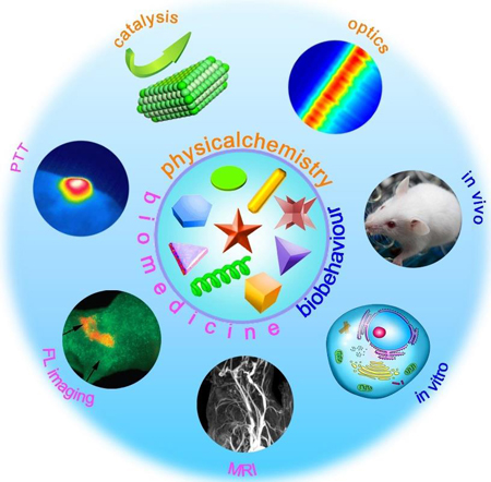
1. Introduction
The shape or anisotropy is known to be intertwined with many parameters, which has a considerable effect on physical, chemical and physiological characteristics of nanoparticles (NPs).1–3 Precise control of their morphology impacts profoundly on regulating them as desired for various physicochemical and biomedical employments. As far, numerous nanomaterials in clinical use or research in the laboratory are of spherical shape. Whereas, in the recent two decades, there is also a fast development of NPs with anisotropic morphologies for various applications (Figure 1).4–13 A number of well-designed strategies have been undertaken to utilize NPs with different morphologies, such as regulating anisotropic shape to tailor their optical and catalytic characteristics.14–17 On the other hand, shape engineered materials are also widely used in biomedical field such as fluorescence imaging,18, 19 magnetic resonance imaging,20 and photothermal therapy.21 Meanwhile, shape factors influence cytotoxicity,22, 23 uptake,24, 25 target,26 biodistribution and pharmacokinetics of NPs.27–29 For in vivo studies, anisotropic NPs are usually used to improve tumor targeting due to their prolonged circulation time and altered biological fate.30, 31
Figure 1.
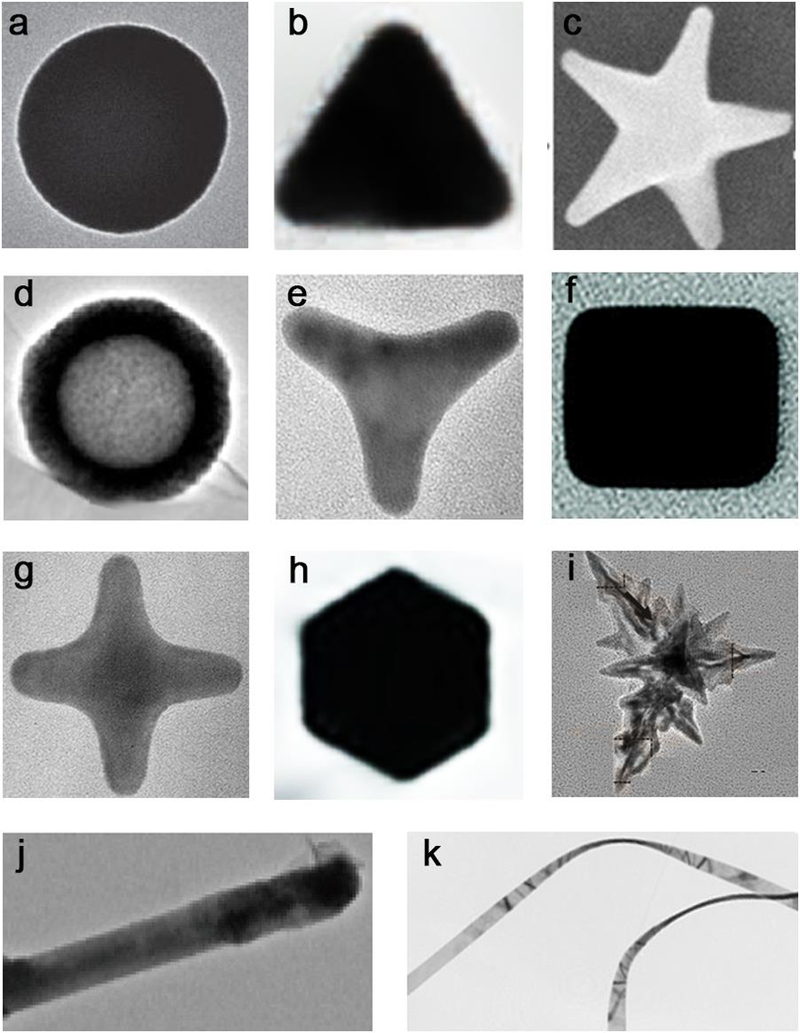
(a) NiCo sphere, (b) Au triangle, (c) Au star, (d) hollow TiO2/GC, (e) Au tripod, (f) Ag cube, (g) Au tetrapod, (h) PtPb hexagon, (i) Fe3O4 branches, (j) MoS2/CdS rod, (k) Au belt. Reproduced with permission from refs 4–13. (a) Reprinted with permission from ref 4, copyright 2015 Nature Publishing Group. (b, c) Adapted by permission from refs 5 and 6, copyright 2017 and 2008 Wiley-VCH. (d, e, f, g, i, j, m, and k) Reproduced with permission from refs 7, 8, 9, 11, 12, and 13, copyright 2015, 2003, 2010, 2015, 2016, and 2008 American Chemical Society, respectively. (h) Adapted with permission from ref 10, copyright 2016 American Association for the Advancement of Science. The backgrounds of some figures are removed for clarity, details for original images and scale bars please see the relevant references.
The most attractive point about nanotechnology origins from the possibility to precisely engineer its physical, chemical and biological properties. Changes of structural parameters such as shape and size typically alter the chemistry and structure of NPs, which could be controlled to achieve desired behaviors in physicochemical properties and biological applications.32, 33 However, at present, the great majority of systems are spherical due to their convenience in synthesis and a lack of full understanding of their structure-activity relationships in morphology. As researchers, we should envision that the future NPs in physical chemistry and nanomedicine could be engineered as we expect and have a definite form that follows their function. It is essential to establish intrinsic correlation of these well characterized NPs with various anisotropic shapes and their physicochemical and biomedical performances through the bridge of chemical structure and biological effect, by which foreseeable insights and unambiguous strategies can be achieved. With these insights, we could develop nanomaterials as desired through a rational design instead of trial-and-errors.
In this review, we summarize the past two decades of studies on NPs-based materials with different shapes in physicochemical and biomedical applications, e.g., optics, catalysis, imaging, or therapy, with a specific focus on the impact of shape. We give a systematic statement around these NPs from mechanism, synthesis, property to application. Their biological behaviors, such as toxicity, uptake, and target are discussed as well.
To date, specific kinds of materials, synthetic methods, or biomedical applications have been studied in lots of researches and a huge volume of published data were produced on these topics. However, their interactional and interdependent relationships are ignored, integrating them together is rather challenging due to the interdisciplinary nature. Herein, we are concerned with different shaped NPs and mainly divide them into several parts: (1) theoretical mechanisms of shape-dependent effects, (2) primary synthetic approaches of anisotropic NPs, (3) physicochemical and (4) biomedical applications, (5) shape induced biological behaviors. Several principles are raised to help design future NPs. Moreover, some critical challenges and open questions that need to be addressed are proposed.
2. Mechanisms of the shape-dependent properties
The shape influences many related physical, chemical and physiological factors of NPs, thus differentiate in their physicochemical (such as catalytic and optical), biomedical, and biological performance.34 A systematic understanding of the mechanism of shape-dependent effect on NPs is essential to predict their properties and explore their applications.
Fully harnessing the power of anisotropic shaped nanocatalysts requires a detailed understanding of the intrinsic essence of their enhanced performance at the atomic level, which in turn requires a fundamental knowledge of their geometric and electronic structures. Metal NPs with different morphologies and structures endow them with various optical properties and applications in photonics.35 The main theoretical mechanism is that the adsorption energy of adsorbents and the activation energy of reactions on different metal facets are discrepant due to their different surface atomic and electronic structures.36 Therefore, the activity for many optical procedures can be modulated and optimized by trimming the anisotropic shapes and exposing facets. In addition, metallic nanostructures supporting surface plasmon resonances with collective excitations of the conduction electrons exhibit unique optical properties.37 Modifying their structures or geometric parameters is a convenient way to tailor surface plasmon resonance properties for specific applications.38, 39 The plasmon resonance depends strongly on particle length and shape. The dipole plasmon resonance gradually red shifts as the length-to-width ratio increases. For instance, the color of gold NPs in colloidal dispersions can vary from blue to red as the particle becomes more oblate.40 When the polarization is chosen to be along the minor axis, there is a second resonance arises that plasmon resonance has blue shifts as the particle becomes more oblate. The color and optical properties of metal NPs stem from localized surface plasmons, anisotropic shapes such as rods have an additional absorption peak and possess quite different characteristics. In consequence, metal NPs with different shapes and aspect ratios exhibit distinct localized surface plasmonic resonance (LSPR) and surface enhanced Raman spectra (SERS) properties.41, 42 Nanomaterials also have size and shape dependent nonlinear optical properties,43 and the shape effects can be separated from the localized surface plasmon wavelength by comparing the solution with a similar linear extinction at the laser excitation wavelength.44
In most cases, catalytic behavior highly depends on the shape of the catalyst, since nanocatalysts with different anisotropic shapes could exhibit different selectivities and/or activities.45–47 One account for such shape dependence of catalytic property essentially originates from the differences in geometric structure and electronic state of catalyst atoms associated with distinctive crystallographic surfaces.48 As a result, catalysts based on NPs with different crystallographic shapes usually display quite different catalytic performances even for the same catalytic reaction.49, 50 Meanwhile, another reason is that shape with different anisotropy tunes the fraction of atoms of the topmost surface layer of a NP, the proportions of atoms at corner and edge of a particle, and the specific surface area of a catalyst. Adsorption energy and activation barrier depend greatly on the local structure on the reactive surface of NPs with anisotropic shapes. The surface structure of catalyst affects the stability of reaction intermediates and the activation energy of surface chemical reactions in two distinct ways. One is the electronic effect, the difference in local electronic structures due to the surface metal atoms in different environments. The other geometrical effect originates from the fact that various surface geometries provide different configurations for the molecule bonding. They offer atoms with electronic structures different from close-packed surfaces and meantime offer new configurations of surface atoms. But as a function of the reaction energy for different surface geometries, they act different in the transition state energy for chemical reaction on surface, for instance, CH4 dissociation and NO dissociation.51–53 Moreover, the structure sensitivity and reactivity of different facets, which translates directly into the dependence of the rate and selectivity of supported catalysts on size, morphology, and defect density of anisotropic NPs. The distribution of coordination sites (edge, terrace, kink, or corner sites) is dependent on the shape of metal NPs. Various coordination sites could exhibit quite different properties of coordination chemistry toward reactants, intermediates and products (Figure 2)54.
Figure 2.
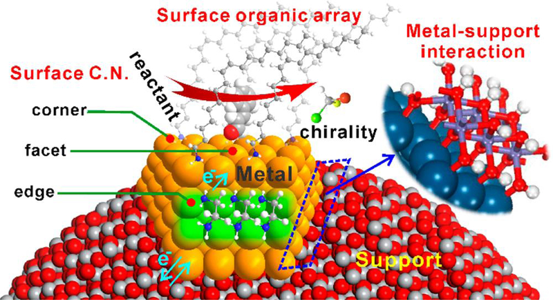
Coordination chemistry on the surface or interface of metal NPs: surface coordination number, surface organic array, metal-support interaction, electronic effect, and so on. The distribution of these coordination sites on the surface is often dependent on NP shape which can tailor the overall catalysis, especially selectivity. Reprinted with permission from ref 54, copyright 2017 American Chemical Society.
The morphology plays an important role in the biomedical applications of NPs. NPs with various shapes show diverse adaptabilities in fluorescence imaging (for instance, metal sulfides and NaGdF4) and photothermal therapy (e.g., Au NPs) due to their different optical performances. The shape plays a significant role in fluorescence imaging because the Stokes shift highly depends on the aspect ratio of nanocrystals.55, 56 Fluorescent NPs can absorb and convert the energy into radiation of visible light,57 trimming their geometrical shape of nanostructures will generate a shift in the scattering and the photoluminescence (PL) spectra.58 Anisotropic NPs with a relatively large size and small surface ratio and thus little surface defects, have high sensitivity and selectivity because of the static quenching and the inner filter effect.59 Moreover, the enhancement of the PL yield is ascribed to anisotropic NP plasmons, especially to the augment of scattering or absorption cross sections.60 Furthermore, the upconversion quenching also can be tuned with surface defects by adjusting of size and shape.
On the other hand, morphology is pivotal for contrast abilities of iron oxide NPs in magnetic resonance imaging as the theory that it influences the effective radius and the local field inhomogeneity of the magnetic core, the surface-area to volume ratio together with the gradient of stray field under an external applied magnetic field.61 Magnetic NPs with distinct shapes generate non-uniform spatial stray fields under the background field owing to the anisotropic characters of magnetic dipole interactions.62 The magnetic relaxation, and the dephasing and efficient diffusion processes of the water protons in nearby area, which are affected with local gradients of the stray field by shortening the spin−spin relaxation time.61, 63 The geometrical shape plays an important role in the spatial distribution (intensity, direction, and gradient) of the magnetic stray field.64 The NPs with large shape anisotropy has high intensity and spatial non-uniformity of the stray field, and produces great influence on water proton diffusion and dephasing. Therefore, the morphology largely determines the gradient of stray field and the effective radius, which finally affects the transverse relaxation rate. In the spin−lattice relaxation process of water proton, the exposed metal ions on the surface can provide an efficient chemical exchange for protons and thus accelerate the relaxation process.65 Consequently, the longitudinal relaxivity of NPs has a positive correlation with the surface-area-to-volume ratio and the occupancy rate of effective metal ions on exposed surfaces. In addition, these principles could serve as guidelines for the design of nanomaterial-based agents for sensitive and accurate diagnosis or therapy in the clinic.
Changes in the shape or geometry of NPs can alter the pharmacokinetics and biodistribution of the agent, which in turn alters the toxicological profile.66 The amount and rate of phagocytosis of particles are determined by the radius of curvature where particles contact the surface of a cell. Hence anisotropic NPs are likely to be taken up by cells because their high aspect ratio can lead to more contacts with the cell surface. The shape-independent mechanisms for in vitro and in vivo behaviors are as follows. In vitro toxicity is greatly influenced by type of NP material, degree of particle uptake, and the in vitro model used. NPs with very high aspect ratio can mediate some pro-inflammatory or cytotoxic effects and induce frustrated phagocytosis in professional phagocytotic cells. Meanwhile, anisotropic particles increase the potential of targeting ligands to interact with receptors on cell surface, and this increased valency leads to higher cellular targeting. For in vivo behavior, anisotropic NPs have prolonged circulation time due to flow alignment in circulation and thus could improve in vivo tumor targeting compared to their spherical counterparts.15 The geometry or anisotropy of NPs also has a remarkable effect on their in vivo biodistribution behavior, such as discoidal NPs mainly localize in the lungs/heart and larger anisotropic NPs are prone to accumulate in the spleen.
3. Synthetic approaches
Synthesizing precisely shaped nanostructures is of primary importance because the nanometer-scale structural details of anisotropic shapes can significantly affect their properties. NPs with numerous morphologies and dimensions could be accomplished via various routes and reaction conditions such as temperature, concentration of precursor, or capping agent.67 In other words, the synthetic approach could change the anisotropic shape which has an important impact on altering their anisotropic effects. In this section, we hence mainly summarized the synthetic methods of NPs with common anisotropic morphologies.
3.1. Surface coordination
Partial synthetic methods that enable precise control over NP morphology require agents such as small molecules to force growth of NP in a particular direction by coordinating with the surface metal atoms.54, 68 Therefore, there is a strong relevance between surface coordination and the shape-controlled synthesis. The coordination of small molecule ligands on metal surfaces has inspired numerous experimental and theoretical studies for noble metal NPs.69 For instance, CO prefers to coordinate on Pd{111} facets in bridge and hollow modes.70 By simply introducing CO as the surface confining agent, ultrathin Pd nanosheets with Pd{111} facets as their main exposed face were easily obtained.71–73 Besides, ultrathin Rh nanosheets enclosed by Rh{111} basal planes74, Pt nanocubes with Pt{100} facets75, 76 and Au nanowires77 (Figure 3a) were also formed when CO was introduced in the synthesis. When CO and H2 were used simultaneously, single-crystalline Pd tetrapods enclosed by {111} facets were obtained (Figure 3b).78 In addition to CO and H2, many other small molecules regulating the surface structures and shapes of metal nanocrystals have been demonstrated. Yang et al. reported that NO2 binding contributes to prepare nanocrystals with more Pd{111} facets exposed due to the stabilization effect of NO2 on Pd{111} facets (Figure 3c).79 Moreover, the coordination of amine on low coordinated metal site provides an effective strategy to prepare concave Pt NPs with {411} high-index facets (Figure 3d).80
Figure 3.
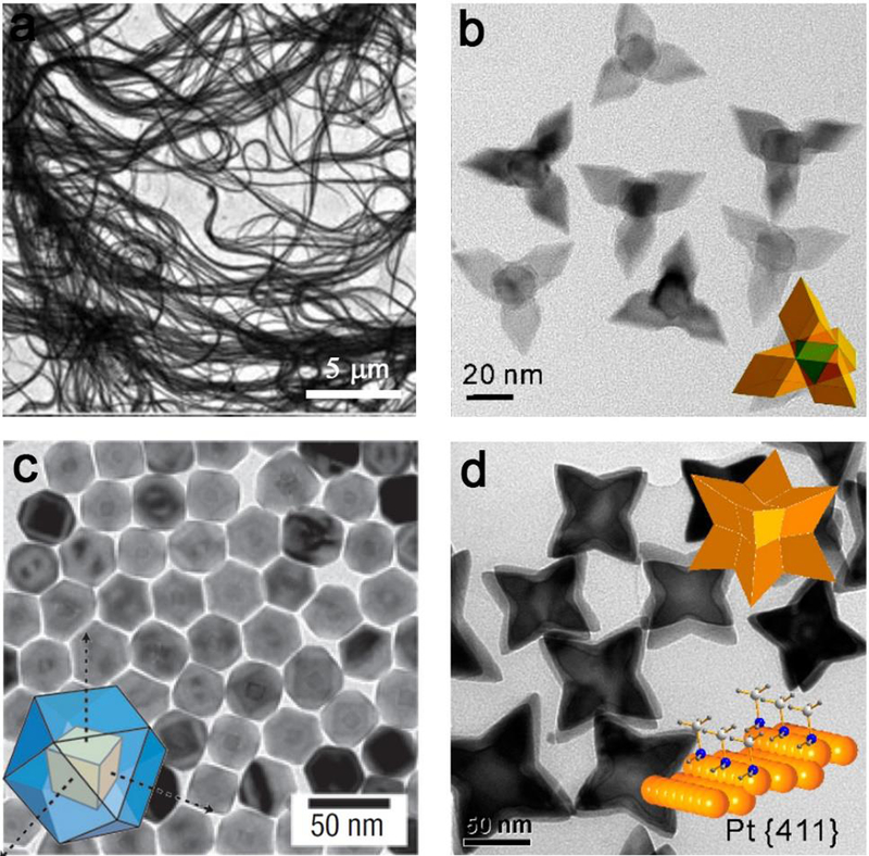
The effect of surface coordination of small ligands on the shape-controlled synthesis of metal nanocrystals. (a) Au nanowires made by the bonding of CO. (b) Pd tetrapods formed by the use of CO and H2; (c) Pt/Pd core–shell cuboctahedra by direct growth of Pd on Pt nanocubes achieved with the addition of NO2. (d) Amine-assisted formation of Pt octapods enclosed by high-index {411} facets. The scale bars in (a-d) are 5 μm, 20 nm, 50 nm and 50 nm, respectively. (a) Reprinted with permission from ref 77, copyright 2010 Royal Society of Chemistry. (b) and (d) Reproduced with permission from refs 78 and 80, copyright 2012 and 2011 American Chemical Society. (c) Reproduced with permission from ref 79, copyright 2007 Nature Publishing Group.
A significant numbers of syntheses of NPs with various morphologies need other capping agents (e.g., certain species of ions or polymers).81 The absorbing or binding of capping agent would protect specific facets or significantly reduce the surface energies of facets, thus leading to the confined growth in a particular direction. For instance, halide, such as cetyltrimethylammonium bromide, has been well-documented as a critical factor to control the shape of various NPs.82–84 Similarly, Rh nanocubes, Pd nanocubes and nanowires, were synthesized owing to the selective binding of halides on Pd/Rh{100}.85–87 Whereas in another case, octapod iron oxide NPs were successfully fabricated by the special selectivity of chloride anions capping rather than other halide ions.88
A variety of reagents can be altered to change the shape of the NPs in the synthesis process. Besides halides, the concentration of Au salt, silver nitrate, and ascorbic acid can be adjusted to gain Au nanospheres, pentagonal twinned Au nanorods, and trisoctahedral Au NPs (Figure 4).89 The initial gold seed is generally formed by the reduction of gold salt (e.g., HAuCl4) by a reducing agent, together with a weak binding ligand (such as citrate or cetyltrimethylammonium bromide, CTAB). The size or morphology of the Au NPs can be firstly tuned by the anisotropic shaped seeds with the using of capping agents, such as CTAB-stabilized cuboctahedra Au NPs, citrate-stabilized pentagonally twinned Au NPs, or silver nitrate-utilized Au nanorods (Figure 4I). Other capping reagents can be employed as synthetic handles and interact synergistically to direct the shape-controlled growth of NPs, including the halide counterion (Cl−, Br−, I−), the relative concentrations of Au salt/silver nitrate/ascorbic acid, and the concentration of the surfactant (Figure 4II). Hence a number of anisotropic Au products were prepared, such nanospheres, single-crystalline rods (aspect ratios of 3.5−15), and trisoctahedral structures (Figure 4III a–e).
Figure 4.
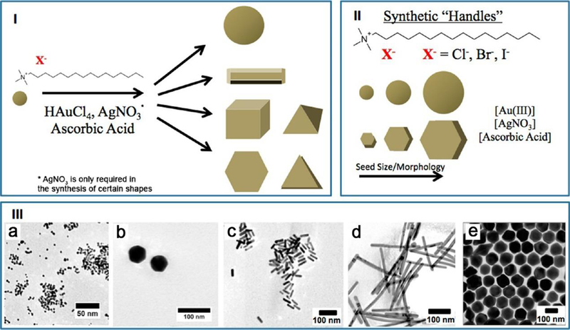
Several capping agents used to prepare Au NPs with a wide variety of shapes. (I) The general conditions for synthesizing anisotropic Au NPs. (II) A variety of reagents can be employed to change the shape of Au NPs, which provide synthetic handles to control the shape, including the corresponding halide counterion, the concentration of the surfactant and Au salt, silver nitrate, and ascorbic acid. (III) TEM images of Au NPs with different shapes: (a) 3.0 nm Au nanospheres, (b) 40.0 nm Au nanospheres, (c) Au nanorods, (d) pentagonal twinned Au nanorods, and (e) trisoctahedral Au NPs. Reprinted with permission from ref 89, copyright 2014 American Chemical Society.
This growth approach for the synthesis of gold NPs can also been extended to other related metals, such as copper and silver, or even platinum and palladium. The only principal difference among these growth approaches applied to obtain different anisotropic nanocrystals is the compositions of the growth solution. Moreover, this method can also be further extended to evaluate and screen the facet selectivity of a given capping agent. For instance, Zeng et. al realized control of the shapes of silver nanocrystals with different capping agents.9 The binding of citrate to {111} facets is stronger than that of {100} facets of face-centered cubic Ag. In the presence of sodium citrate, the growth rate of {111} facets is slower than that of {100} facets during a seeded growth process. Therefore, {100} facets will gradually disappear while {111} facets will become dominant, eventually leading to the formation of Ag octahedrons. However, on the contrary, PVP binds more strongly to {100} than the {111} facets, thus reducing the growth rate along [100] direction. It makes the {111} facets disappear faster than the {100} facets, resulting in nanocubes and nanobars. Jin and co-workers reported the shape‐controlled synthesis of copper NPs in an aqueous solution with glucose as a reducing agent and hexadecylamine as a capping agent.90 It is also demonstrated that the formation of a class of highly faceted planar lanthanide fluoride nanocrystals (nanoplates and nanoplatelets) resulting from the patchy coverage of ligands around the nanoplate edges.91
Meanwhile, the effect of various polymeric capping agents were investigated, such as Tween 80, Tween 20 and PEG on the shape and size of YbVO4/NiWO4 nanocomposites.92 The cations of oleate salts, hydrion, sodium, potassium, and dibutylammonium were found to have great influence on the shape in the synthesis of iron oxide NPs by using iron(III) oleate, and hence the spherical, cubic, and bipyramidal iron oxide NPs were obtained.93, 94 In a similar manner, monodisperse octahedral iron oxide NPs were obtained by using oleylamine as a stabilizer and reducing agent.95 Besides, Liu et al. experimentally verified the co-existence and different roles of oleate anions (OA) and molecules (OAH) in the crystal formation, the control over the ratio of OA to OAH can be employed to directionally inhibit, promote or etch the crystallographic facets of NaYF4 NPs (Figure 5).96 With such programmable additive and subtractive engineering, fabricating NPs with a variety of anisotropic shapes can be implemented.
Figure 5.
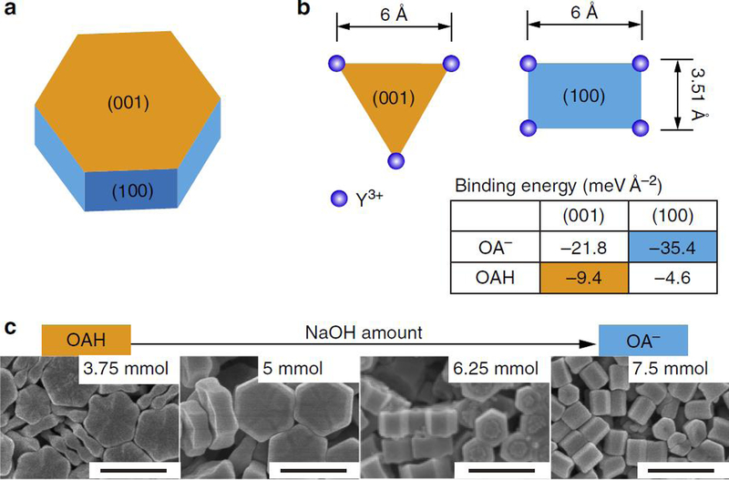
Favored molecular capping or bonding models of OA- and OAH of β-NaYF4 nanocrystals. (a) The schematic shape chosen as the core for directional epitaxial growth. The hexagonal plate consists of the (001) facets at the ends, and identical (100) and (010) facets around the sides. (b) The Y3+ arrangements and binding energies of OAH and OA- on the most stable (001) and (100) facets. (c) SEM images of nanocrystals synthesized using varied ratios of capping agents (scale bar, 500 nm). Reprinted with permission from ref 96, copyright 2016 Nature Publishing Group.
3.2. Physical parameters
Physical parameter such as pH and temperature have important impacts on the shapes or anisotropy of NPs, since they influence the crystal nucleus formation and the growth or evolution of particles directly. Recently, the significance of pH has been realized and the manipulation of NPs by tuning pH is reported.97–101 Xue and Mirkin found that the silver nanoprism could be tuned by different pH values in the photochemical synthesis.102 In this case, the excellent control over nanoprism with an edge length of fixed 10‐nm thickness were implemented with appropriate pH regulation. Li et al. reported that pH value varies the morphologies of LaCO3OH microcrystals in the growth (Figure 6).103 The nucleation and then the crystal formed after the dissolution of CO(NH3)2 which was used as the carbon source. Then a selective adsorption of OH- on the crystal took place at different pH values. Finally, the multiform products were formed due to this preferential growth direction of the LaCO3OH crystal. Their shape undergone changes from elliptical nanoflakes (pH = 2) to rhombic microplates (pH = 7), and then to sandwichlike microspindles (pH = 10).
Figure 6.
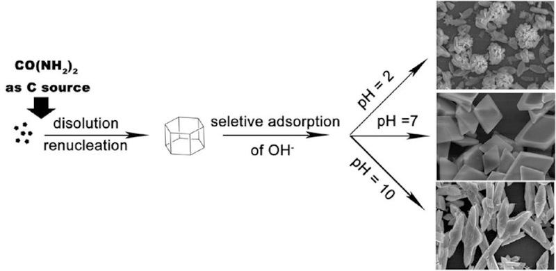
Schematic illustration of the possible growth process of LaCO3OH microcrystals with various shapes at different pH values (2, 7, and 10). Reprinted with permission from ref 103, copyright 2010 American Chemical Society.
The temperature plays an important role in the thermodynamic control in solution phase, which is a simple and effective strategy that is easily achieved during an experiment. As a result, the thermodynamic control has been widely applied for the shape-controlled synthesis of nanocrystals.104–106 The hexagonally closely packed (hcp) ruthenium hourglass nanocrystals can be achieved by the shape control from thermodynamic growth.107 Li and Peng reported the temperature effects of the shape-controlled synthesis of colloidal CdSe quantum disks.108 They found that a proper temperature range (approximately 140 to 250 °C) is needed for the successful synthesis of CdSe quantum disks. Because the up-temperature limit is dictated by the close packing of hydrocarbon chains in fatty acids, and the low-temperature limit is related to the reactivity of initial materials. Likewise, Guo et al. reported the shape-controlled synthesis of SnTe nanostructures by regulating the temperature.109 The shapes are tunable from highly monodisperse nanocubes to nanorods with varied aspect ratios, and eventually to long and straight nanowires (Figure 7). They discovered that the reaction at high temperature fast forms thermodynamically favored nanocubes, while low temperature leads to elongated particles. The distinction of growth and shape-focusing is likely due to the interparticle ripening differences at various temperatures.
Figure 7.
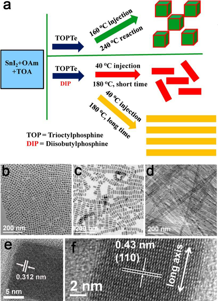
(a) Schematic illustration of controlled syntheses of SnTe nanocubes and nanorods with various aspect ratios. (b,c) TEM and (e,f) corresponding HRTEM images of SnTe nanocubes and nanorods. (d) TEM images of SnTe nanowires prepared with Tinj = 40 °C, Tr = 180 °C, and tr = 8 h. Adapted with permission from ref 109, copyright 2015 American Chemical Society.
Meanwhile, the kinetic parameter is equally important and well explored to control the shape. Taking the shape growth of a cubic seed as an example, the newly formed atoms should be deposited onto the corners owing to the high energy of these sites (Figure 8).110 The adatoms can deposit onto the corner sites or diffuse to different surfaces. The growth pathway thereby the shape of the product has a strong dependence on the rates for atom deposition and surface diffusion (i.e., Vdeposition/Vdiffusion), which leads to four different geometrical shapes in the end.
Figure 8.
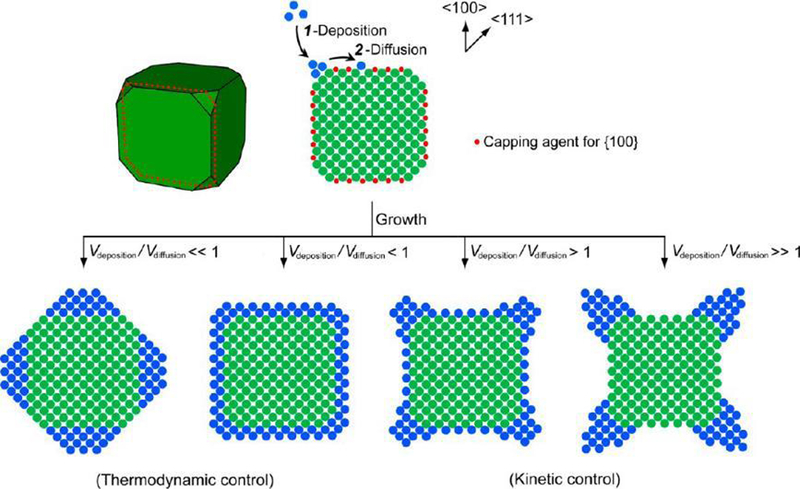
The schematic illustration of the shape evolution of a cubic seed under different conditions. The side faces of the seed are covered by a capping agent to show the difference, and the anisotropy and shape could be totally different by the thermodynamic and kinetic control. The 2-D atomic models in this figure correspond to the cross-section of the 3-D model. Reprinted with permission from ref 110, copyright 2015 American Chemical Society.
3.3. Seed growth
Seed‐mediated growth is a powerful and versatile means for the preparation of anisotropic nanocrystals.111–114 The vast enchantment of this method stems from the fact that nucleation and growth steps are separated, hence allowing an astonishing degree of control over the shape and aspect ratio, which could influence the properties of nanocrystals and determine their performance in various applications.115–117
The seed-mediated synthesis approach includes two main strategies, homogeneous and heterogeneous growth. If the seed crystal and the final crystal are composed of the same metal, then it is a homoepitaxial process, and the diverse morphologies of NPs can be expanded with endless possibilities by applying seeds with controllable internal structures. This approach is exploited by most of groups to obtain metal nanostructures with precise control over the size and aspect ratio. For instance, Zhang et al. recently demonstrated that Ag nanocubes with controllable edge lengths of 30–200 nm can be achieved by using cubic single crystalline as seed.118 While penta-twinned Au NPs, with preselected morphology (nanorods, bipyramids, and decahedra) and aspect ratios, were formed by using small conventional Au seeds (Figure 9a–d).119 The thermal treatment induces both growth and twin formation of the traditional NP seed. Keeping all other parameters constant, the aspect ratio for each type could be readily tuned by simply varying the concentration of thermally treated seed. Consequently, these grown penta-twinned NPs with different shapes were obtained. Similarly, triangular Au nanoplates were produced by oriented attachment of spherical Au seeds (Figure 9e).120 Spherical Au seed particles were produced within a few hours after irradiation. The contact between seeds led to oriented attachment at the correct crystallographic alignment, resulting in the flake structures. Then the aggregation of these small flakes with additional seeds forms polycrystalline plates by adding H2O2. Ultimately, the triangular crystalline Au plates were formed by the recrystallization of these polycrystalline plates and the continued attachment of seeds at the edges. In another case, Au nanobipyramids (NBPs) were produced from decahedral Au seeds due to the overgrowth on penta-twinned decahedra (Figure 9f–m).121 The penta-twinned decahedral Au seeds are critical to the formation of NBPs because the free-defect overgrowth of the penta-twinned NBPs could be easily accomplished on these decahedral seeds with penta-twinned structures. In the overgrowth, {100} facets with relatively high surface free energy were selectively adsorbed by protecting agents or Ag-based species. As a consequence, the selective deposition on {111} along ⟨110⟩ occurs fast, which generates one dimensional NBP. Meanwhile, the production of NBPs is mainly determined by the molar ratio of Au3+ and Au seeds. NBPs with a yield higher than 90% was realized when the ratio ranged from 8 to 10. Moreover, these prepared NBPs exhibited excellent SERS performance in virtue of many present tips, hotspots, edges, and steps on their surfaces. The homogeneity and quality of the seeds in these methods make it easier to supervise the shape evolution throughout the growth process, and guarantee a common mode for all seeds involved to afford uniform products.
Figure 9.
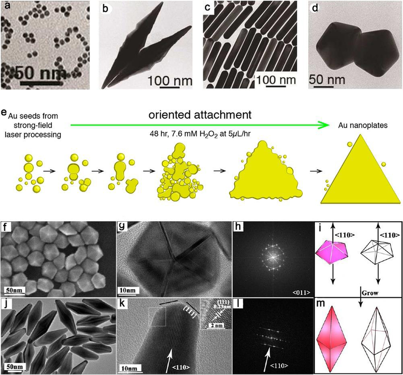
(a) Representative TEM image of the gold seeds with thermally-induced twinning for 90 min at 80 ºC. TEM images of NPs with (b) bipyramids, (c) nanorods and (d) decahedra shapes, showing the effect of seed concentration on the formation of NP in a single growth step. (e) Schematic illustration of the sequential steps leading to triangular Au nanoplate from spherical Au seeds with a strong field laser processing. (f) SEM image of decahedral seeds with a 30 nm edge, (g) HRTEM image, (h) corresponding FFT pattern and (i) sketch of one decahedron. (j) TEM image of nanobipyramids, (k) HRTEM image (inset, HRTEM image of area marked by the box), (l) corresponding FFT pattern and (i) sketch of one bipyramid. (a-d), (e) and (f-m) are adapted with permission from refs 119, 120 and 121, copyright 2017, 2015 and 2013 American Chemical Society, respectively.
If the seed and the objective crystal consist of different metals, it is then a heterogeneous procedure (Figure 10a).122 This approach is used in the synthesis of penta‐twinned Cu nanorods with controllable aspect ratios, the uniform Pd decahedral seeds lead to the heterogeneous nucleation and determine the growth of Cu along the fivefold axis to form nanorods.123 It was also certified that the ultrathin Pt shell could be formed on the surface of a Pd concave cube as the seed by introducing PtCl42- to accomplish the deposition of Pt atoms (Figure 10b).124 Another type of seed-mediated growth approach is a two-step process for growing the shell of CdSe/CdS core/shell nanorods, which combines an first established fast-injection based step to create initial elongated shell and a second slow-injection growth of the core.125
Figure 10.
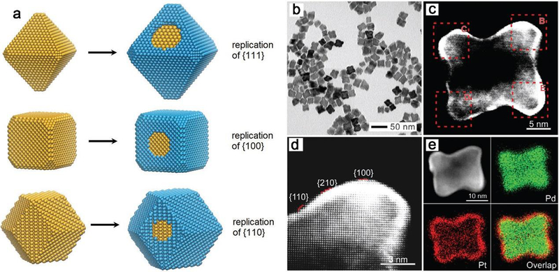
(a) Schematic illustration of the approach employed to control the growth of nanocrystals. Replication of surface structure, ultrathin layers formed on the surface of seed in a layer-by-layer fashion. (b) TEM image of Pd@Pt core–shell concave nanocubes, and (c) corresponding HAADF-STEM image and (d) high-magnification image, showing replication of the high-index faceting and the Z-contrast between the Pd seed and the Pt shell. (e) Elemental mapping of an individual Pd@Pt concave nanocube, showing the distribution of Pd and Pt atoms, which confirmed the deposition of ultrathin Pt shells on Pd concave nanocubes. (a) and (b-e) Adapted with permission of ref 122 and ref 124, copyright 2018 and 2016 Wiley-VCH.
In addition to metal nanostructures,126 many metal oxides could be prepared in seed-mediated methods. The size and shape control of spinel ferrite nanocrystals could be accomplished by this way.127, 128 Anatase TiO2 nanorod antennas can be produced from a rhombic core via a nonaqueous colloidal seed-mediated growth method.129 Systematic studies on the growth mechanism in this work reveal that the formation of nanorods and core-antenna nanocrystals based on the seeds involves an epitaxial growth process with specific orientational preference (Figure 11).
Figure 11.
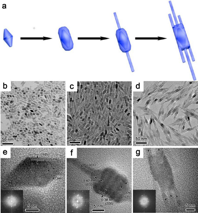
Structural characterization of truncated octahedral bipyramidal nanocrystals seeds and core-antenna nanocrystals after seed-mediated growth. (a) Schematic illustration of the growth pathway of core-antenna nanostructures from seeds. (b) Low magnification TEM image of seed and (c, d) resultant nanorods and core-antenna nanocrystals after seeded growth. (e-g) Typical HRTEM images of the up TEM images, insets are FFT patterns (along the [100] zone axis). Reproduced with permission from ref 129, copyright 2015 American Chemical Society.
3.4. Template mediated process
Template-mediated method has been well developed as a facile and general route to synthesize NPs, because it can choose an appropriate template to manipulate both the size and shape of the resulting structures.130, 131 The commonly used templates consist of porous template,132–135 surface mask template,136–139 biological and organic template,140–143 and solution-phase template, etc.144–146 For instance, the syntheses with solution-phase template, including metallic or dielectric core template,147–149 sacrificial template (e.g., galvanic replacement or Kirkendall effect)150–152 and colloidal template, have been applied for developing phase-separated heterogeneous morphologies. In the Au-Pd-Ag hollow nanostructure, the removal of silver is dominated by galvanic replacement in the formation of the binary Pd-Ag structure at the beginning. Later the gaps around these cavities were formed, then it was finally governed by the Kirkendall effect with the adding of the gold salt (Figure 12)153. The disparity between fluxes of gold and silver produced a net flux of vacancies in the surface and the center because the diffusion speed of silver in gold is faster than that of gold in silver. Gu et al. observed the nucleation of Ag domains on Fe3O4 NPs templates after ultrasonic emulsification.154 Ultrasonication offers necessary energy to mix the organic and aqueous phases and allows NPs to self-assemble at the liquid-liquid interface in the microemulsion. Due to the partial coverage or unstable nature of surfactant molecules on NPs, few Fe(II) sites on the surface act as the catalytic center for the reduction of Ag+ and the Ag NP seed. Once the silver nucleation sites formed, the subsequent reduction of Ag+ will proceed at these sites and then Fe3O4-Ag heterodimers are obtained. Similarly, Sun et al. synthesized the dumbbell-like Au|Fe3O4 nanostructures by the decomposition of iron pentacarbonyl, Fe(CO)5, onto the surface of Au templates followed by oxidation under air with precursors in 1-octadecene.155 Another example is CdTe tetrapod-shaped NPs can be employed as colloidal template to prepare nanorods through site selective modification.156 The tetrapods partially coated with a protective polymer layer and deposited on a silicon surface, leaving an exposed arm. After decoration with Au NPs in a site selective fashion, this modified arm were readily broken off from the tetrapods and released from the substrate, yielding CdTe nanorods.
Figure 12.
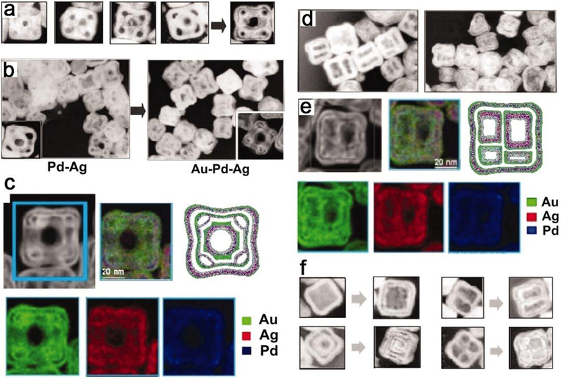
(a) The illustration of the formation of hollow nanostructures via sequential galvanic replacement and Kirkendall effect and (b) the nanostructures dominated by galvanic replacement by Kirkendall effect, and (d) multichambered NPs, all showed in TEM images. (c) and (e) HAADF-STEM images and their corresponding EDX elemental maps. (f) TEM images of different structures synthesized by sequential galvanic replacement or Kirkendall effect. Reprinted with permission from ref 153, copyright 2011 American Association for the Advancement of Science.
On the other hand, the biological and organic templates,157 consisting of DNA,158, 159 peptides and peptide assemblies,160, 161 proteins,162, 163 viruses and microorganisms,164 lipid assemblies and other synthetic supramolecular structures, micelles and emulsions, dendrimers, carbon nanotubes,165 have also been tried. For example, soft templates like micelles and reverse microemulsions, have been used to prepare NPs composed of alloys, metal oxides, inorganic molecules, and noble metals like Ag.166 The surfactant molecules with amphiphilic groups, can form a well-defined structure such as hollow sphere, due to the hydrophobic end only binds with organic solvent and hydrophilic head only binds with water.34
3.5. Other approaches
In addition to the above main synthetic approaches of anisotropic NPs with different morphologies, there are still a number of other routes that have been tested. For instance, the strategy based on a general phase transfer and separation mechanism usually occurred at the interfaces of the liquid, solid and solution phases for noble metal, magnetic/dielectric NPs, rare-earth NPs, semiconducting NPs, organic optoelectronic semiconducting and conducting polymer NPs.167 Another research reported the shape control of cubic, cuboctahedral, and octahedral CuCu2O core-shell NPs on Si(100) could be completed by one-step electrodeposition without capping agent and template.168 The unique shape of NPs is obtained by the synthesis with physical or biological parameter applied, such as light-mediated synthesis or biomolecule introduced preparation, which could be found in plasmon‐mediated synthesis of triangular core–shell nanoprisms from Au seeds,169 silver triangular bipyramids,170 heterometallic nanorods and icosahedra.171 Zhang et al. reported a facile method to synthesize five‐fold twinned, starfish‐like rhodium nanocrystals in a polyol system by eliminating oxidative etching with a chloride‐free precursor (Figure 13).172 The Rh nanocrystals with five branched arms were realized in high yields due to the use of [{(CF3COO)2Rh}2] instead of Na3RhCl6 as a precursor to exclude Cl- ions from the reaction system.
Figure 13.
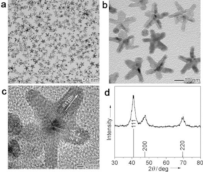
TEM images of starfish‐like Rh nanocrystals with five branched arms obtained using polyol reduction at 180 °C for 6 h, at (a) low and (b) high magnifications. (c) A representative high‐resolution TEM image and (d) the XRD pattern. Adapted with permission from ref 172, copyright 2010 Wiley-VCH.
4. Physicochemical applications
How to regulate the anisotropic shape of metal-based NPs is a linchpin to regulate their physicochemical characteristics, such as optical and catalytical properties. NPs with different anisotropies usually exhibit quite discrepant activity or selectivity in optical reaction. The shape of NPs affects greatly in catalytic performance owing to the diversity in geometric structure and electronic state of the catalyst atoms, together with their different crystallographic surfaces.
4.1. Optical application
Controlling the shape of metal NPs allows us to control their optical properties and applications in Raman, fluorescence or near-infrared luminescence. For example, noble metal NPs (Au, Ag) interact with UV-vis light through the excitation of localized surface plasmon resonance (LSPR), which is highly sensitive to the shape of the nanostructures.173, 174 Targeted shape of metal NPs can be synthesized by controlling the surface sites or undergoing a seed-mediated growth process. Compared with spherical nanostructures, anisotropic shapes such as Au@Ag core-shell nanocubes were prepared by the use of single-crystal spherical Au nanocrystallites as seeds, with cetyltrimethylammonium chloride (CTAC, better than CTAB) as the capping agent and ascorbic acid as the reductant.174 The nanocubes with controllable edge lengths can be finely tuned by varying the ratio of AgNO3 precursor to Au seeds. When the edge length was over 20 nm, the LSPR spectra only showed characteristic features of pure Ag nanocubes and displayed a continuous red-shift with the increasing size. When the edge length continued raising, a split of LSPR peak appeared due to the corners of the nanocubes are sharper than those of the smaller spherical or cubic ones. This method could be applied to systematically investigate the influence on the LSPR properties of the anisotropic core-shell nanocrystals, and obtain the critical edge lengths or shell thickness for the plasmon excitation.
4.1.1. Raman scattering
Plasmonic nanostructures is of paramount importance because the structural details can significantly influence their plasmonic properties.175–178 Precisely structured nanocrystals with anisotropic shape of corner sharpness compared with spheres can provide highly plasmonic signal generation and SERS enhancement.179, 180 The shape effect in SERS of anisotropic NPs (such as Ag and Au) is an electromagnetic enhancement, which is owing to a shift of the localized surface plasmon resonances.181, 182 It modifies the local field enhancements on the particle surface compared with that of a sphere. SERS enhancement can be magnified at the tip of elongated metal NPs when the excitation is polarized along long axis.183 This tip or corner effect, is also called the “lightning rod effect”, which can result in large electric field and Raman enhancement near the sharp surface or at the sharp ends of the NPs. Hence the spatial anisotropy is ascribed to strong optical scattering and plasmon concentration at corners and edges of nanostructures.184 Compared to nanospheres with smooth surfaces, another factor which plays a vital role in SERS is the “hot spots” in the surface due to the presence of sharp edges or active rough surfaces.185 The degree of localization at the hot spot is an intrinsic property of the shape or aspect ratio of the particle,186 which can be traced back to that the magnitude of the induced dipole is affected by the shape. The high Raman signals enhancement is attributed to that more intense local electromagnetic fields generate at the hot spots, which make them more effective Raman scattering than nanospheres.185, 187
Among these controlled shaped nanostructures, gold nanocrystals are most commonly employed due to their unique plasmonic properties and Raman scattering properties. Au NPs with the desired cube shape of highly controlled corner sharpness can scatter light in a steadily reproducible manner, and the quantitative SERS enhancement factors for the dimers are very narrowly distributed (Figure 14a).188 Particularly, the enhancement factors of 72 nm sharp-cornered Au NC dimers have a distribution within one order of magnitude. It is proved that hexoctahedral Au nanocrystals enclosed exclusively by high-index {321} facets exhibit more enhanced plasmonic properties and higher SERS activities than normal spherical ones (Figure 14b).189 In addition, branched Au/Pd bimetallic NCs exhibit much better plasmonic properties and SERS activities than spherical Au/Pd NPs (Figure 14c).190 Moreover, Au nanorods showed red-shifted LSPR spectra with increased aspect ratios,191–194 and would shift their LSPR peaks to shorter wavelengths with Ag shell coating.195, 196 For other nanomaterials such as Ag NPs, anisotropic nanocrystals showed enhanced SERS signals compared with their spherical ones.118 The SERS signal extracted from a single Ag nanocube strongly depends on laser polarization. Compared with isotropic sphere, the intensity of the SERS signal of a cube with the laser polarization along the face diagonal is much stronger than that of the SERS signal along the edge. This phenomenon is caused by the difference in near-field distribution over the surface of a nanocube under different polarization directions. This systematical comparison and investigation of LSPR and SERS properties could also shed light on the design of the best substrate for SERS.
Figure 14.
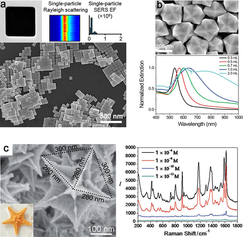
Characterization of anisotropic NPs and their optical properties. (a) Representative TEM image, Rayleigh scattering and the quantitative surface-enhanced Raman scattering (SERS) enhancement factor (EF) of a single-particle, and SEM image of Au nanocubes with sharp cornered shapes. (b) SEM image of the hexoctahedral Au NPs and their normalized UV-vis extinction spectra prepared with different amounts of HAuCl4. (c) High-magnification SEM images and SERS spectra of crystal violet adsorbed on the concave branched Au/Pd bimetallic nanocrystals. The scale bars of (a), (b) and (c) are 500 nm, 200 nm and 100 nm, respectively. The SERS spectra were obtained with lex = 514 nm excitation, Plaser = 1 mW, and t = 20 s. (a, b) Reprinted by permission from refs 188 and 189, copyright 2018 and 2012 American Chemical Society. (c) Adapt with permission from ref 190, copyright 2015 Wiley-VCH.
4.1.2. Fluorescence imaging
The anisotropy or geometric shape of NPs is considerably significant for their applications in fluorescence imaging. Quantum dots (QDs) for fluorescence imaging are the most representative candidates among all fluorescent nanomaterials because of their broad excitation spectra, narrow fluorescence emission bands, and resistance to photobleaching. The PL intensity and wavelength in QDs can be tuned mainly by engineering their size, shape, and composition.197–199 Size-dependent fluorescence properties are generally found in typical 2−10 nm semiconductor QDs.200, 201 With decreasing size of QDs, the energy gap expands between the top of the valence band and the bottom of the conduction band, and this increase in energy associated with exciton generation/recombination brings a blue shift in both absorbance and PL spectra.202 Tailoring composition can be achieved by forming core/shell structures which is divided into three types based upon the band alignment of valence and conduction bands between their constituent materials.203, 204 For instance, Cd-based type II QDs exhibit near-IR emission due to electron−hole recombination across the core/shell interface,205 and Cd-free type II QDs with PL colors changing by simply varying the shell thickness.206 Adding a shell can also improve the PL quantum yield.207 Another method of trimming composition is doping by adding another metal or tuning the ratios of metal precursors to alter the PL peak.208, 209 In addition, the intensity of the emission can be engineered by adjusting pH,210, 211 and the PL wavelength can be fabricated by varying the synthetic temperature.212
The shape effect in controlling the fluorescence property of semiconductor QDs have attracted the researchers’ interests in these years. For example, the synthesis and fluorescence imaging of tetrahedral InP and CdTe/CdSe core/shell QDs were systematically studied.213, 214 Quantum rods (QRs) are brighter probes than QDs since the Stokes shift is greatly dependent on the aspect ratio (length/diameter) of rod.55, 56 Meanwhile, the color control is achievable by tuning the diameter, which governs the band gap energy of QDs.215 With the increase of width or length, the emission peak moves to lower energy, and the position of emission peak depends more sensitively on the width than on the length. The reason for this is that the band gap is chiefly determined by the lateral confinement which plays a vital role even in long rods. Likewise, it was reported that CdSe QRs emitted light that was linearly polarized towards the c-axis of the crystals and the degree of polarization rests with the aspect ratio of the NPs.216 Yong et al. reported CdSe/CdS/ZnS QRs as targeted optical probes for live cell fluorescence imaging.217 In this paper, transferrin (Tf) was conjugated onto CdSe/CdS/ZnS QRs for targeted delivery, confocal and two-photon imaging proved that the receptor-mediated uptake of the bioconjugates into the HeLa cells (Figure 15). In addition, Deng and co-workers found that manganese-doped zinc sulfide quantum crystals with a rod shape have tunable dual-color and multiphoton emissions.218 As reported, in addition to the effect of Mn2+ doping levels, as the increase of QR diameters from QR1 to QR7 with different aspect ratios, the relative intensity of the blue bands to orange bands decreases, which is mainly attributed to the enhancement of orange emission intensity, while the intensity change of blue emission is negligible.
Figure 15.

Confocal microscopic images of HeLa cells, (a) the florescence image and (b) their corresponding transmission image, treated with transferrin-conjugated CdSe/CdS/ZnS quantum rods. Confocal microscopy images were obtained with laser excitation at 442 nm. (c) TEM image of CdSe/CdS/ZnS quantum rods casts from nonpolar organic solvent. The average diameter and length of the nanorods are 14 and 4 nm with an aspect ratio of 3.5. The scale bars of (a) and (b) are 23.81 nm, (c) is 50 nm. Adapt with permission from ref 217, copyright 2007 American Chemical Society.
Shape also plays a significant role in determining the optoelectronic properties of graphene quantum dots (GQDs).219 The emission of GQDs can be widely tuned from deep ultraviolet to near-infrared by its shape of the carbon network.220 A pristine armchair-edged GQD (arranged in rectangle shape) emits red fluorescence (670 nm) in toluene,221, 222 which is attributed to the transition from ground state to excited singlet state.223 While GQD in triangular shape emits red fluorescence at 748 nm and shows the absorption maximum at 591 nm.221, 224 Moreover, Shan et al. also discovered the hidden effect of particle shape and criteria for evaluating the upconversion luminescence of lanthanide doped nanophosphors (Figure 16).225
Figure 16.
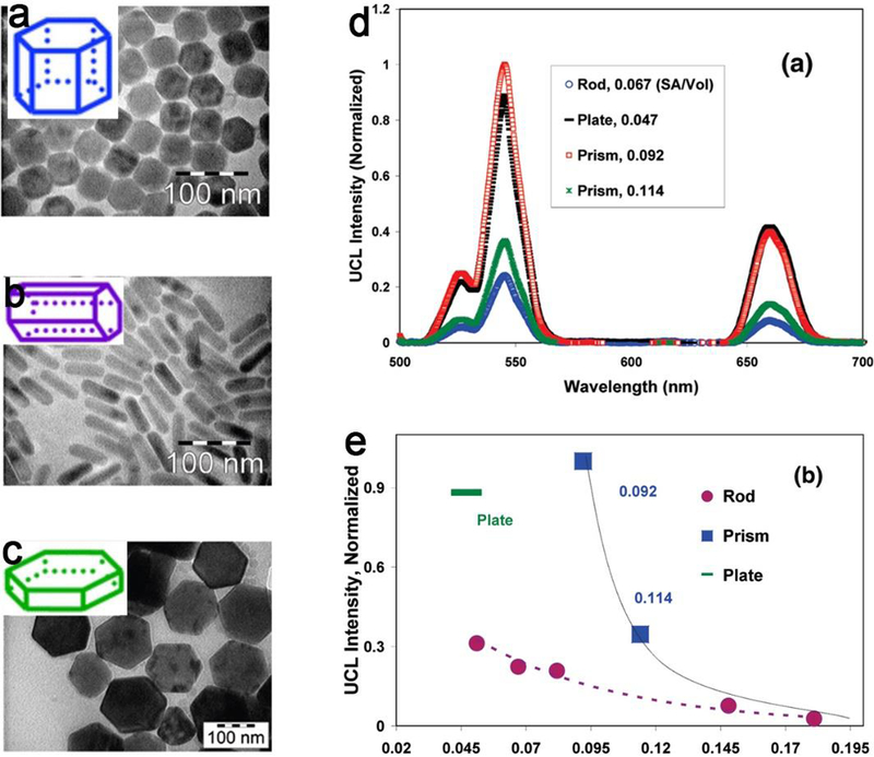
TEM images of the upconversion NPs in three shapes (a) nanoprism, (b) nanorod, (c) nanoplate, insert is the geometrical description of the shape. (d) The upconversion emission spectra and (e) surface to volume ratios vs upconversion luminescence intensity for three upconversion NPs with three shapes. Adapt with permission from ref 225, copyright 2016 American Chemical Society.
4.1.3. Near-infrared luminescence
Near-infrared (NIR) luminescence is commonly found in fluorescence imaging and bioimaging.226–228 Most of previous studies focused on the size and metal doping of NPs for NIR luminescence,229–231 whereas, a few studies noticed the considerable effect of shape on luminescence.232–234 Besides the conventional metal-based NIR luminescence, such as QDs and upconversion NPs, Li et al. realized the morphology‐tailoring of a red AIEgen from pristine nanorods to nanospheres for NIR fluorescence imaging by encapsulating quinoline-malononitrile‐2 (QM-2) into hybrid micelles.235 This nanostructure exhibits great promise in NIR imaging due to its good solubility in aqueous systems, the uniform diameter of about 30 nm, an increased fluorescence brightness with a large Stokes shift of 190 nm, and the strongly enhanced photostability (Figure 17).
Figure 17.
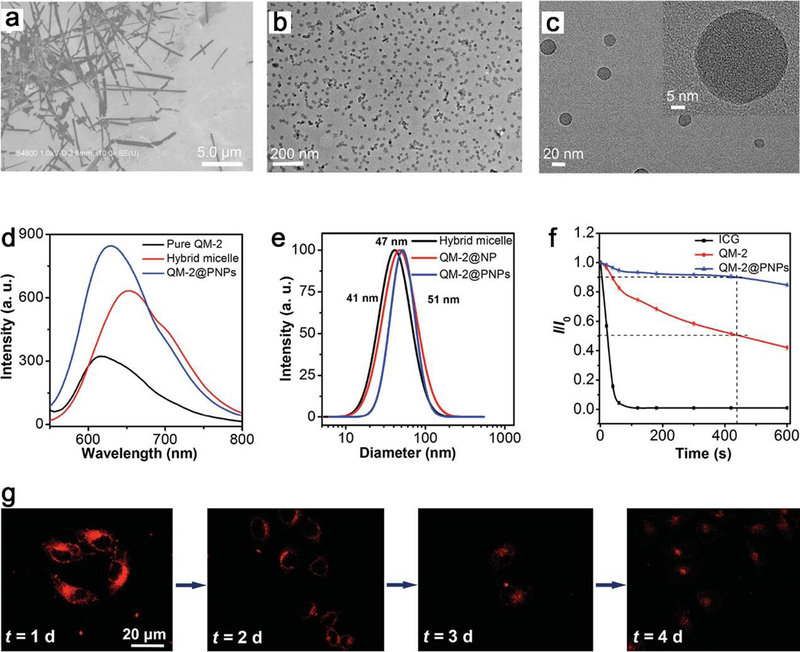
(a) The SEM image of QM-2 in water/THF mixture with fw = 70 vol%. TEM images of QM-2@PNPs at (b) low and (c) high magnifications. (d) Emission spectra of pure QM-2 in water/THF mixture at fw = 70 vol%, hybrid micelles before shell cross-linking, and QM-2@PNPs in water. (e) Size distributions of hybrid micelle, QM-2@NP and QM-2@PNPs in water by dynamic light scattering. (f) Fluorescence stability of ICG (indocyanine green, a FDA-approved NIR imaging agent in clinic), QM-2, and QM-2@PNPs under continuous illumination (0, 10, 20, 40, 60, 120, 180, 300, 420, and 600 s). (g) Fluorescence images of MCF-7 cells stained by QM-2@PNPs at different cell passages. The scale bar (20 μm) is the same for all images. Reproduced with permission from ref 235, copyright 2016 Wiley-VCH.
4.2. Catalytic application
Nanocatalysis is undergoing an explosive growth. Researchers have reported striking novel catalytic properties for nanocatalysts compared to their bulk counterparts, including significantly enhanced reactivities and selectivities.236, 237 Many studies elucidate the factors that tremendously affect the catalytic performance of metal NPs such as their size, shape, or interaction with their support.238 However, these preceding parameters are not independent, for instance, size and support of NPs decide the most stable shape of NPs, which makes the analysis more complicated. Among these aspects, the shape-dependent effect in catalysis attracts increasing attention in recent years. It has been verified that the exposed crystal faces, determined by the morphology of catalyst NPs, considerably affects the catalytic behavior. The surface structure of exposed crystal face has a critical effect on the adsorption energy, reaction energy and activation barrier. Nanocatalysts with various anisotropic shapes often expose several different facets, together with other types of sites such as edges or corners. In a reactive environment, the reactants and products are able to induce other facets or completely new structures to be exposed. Undercoordinated sites at edges and corners are commonly particularly important for the catalysis. On the other hand, the potential energy diagram for surface reactions usually depends greatly on the surface structures of facets. For example, comparing the potential energy diagram for CO dissociation on different Ni facets, steps on the surface interact closely with the final product.239 The dissociation barrier is also considerably lower, which means that not all sites on a nanoparticle contribute equally to the catalytic activity. Any process involving dissociation can be strongly favored at defects and the edges or corners of anisotropic particles.
4.2.1. Photocatalysis
NP-based photocatalysis is one of the most promising procedures in the sustainable making of organic pollutant degradation, clean energy sources, and hydrogen production from water splitting or carbon dioxide reduction.240–242 The exposed facets associated with shapes play a crucial role in the photocatalytic activity of NPs, which is due to the preferential flow of photogenerated carriers to the specific facets. Recently, the fascinating shape-dependent photocatalytic activity of titanium dioxide crystal facets has attracted enormous interest.243–248 To improve the photocatalytic activity, previous reports mainly focus on increasing the surface area of high-energy exposed facets such as {001} and {100}.249 Whereas, Roy and coworkers demonstrated that the presence of both the high-energy {001} oxidative and low-energy {101} reductive facets in an optimum ratio is equally important for efficient charge separation and photocatalytic activity enhancement (Figure 18a).250 Another research also convinced that the co-exposed {001} and {101} facets of anatase TiO2 are significant for the photocatalytic activity for CO2 reduction into CH4.251 They proposed the “surface heterojunction” concept based on the density functional theory (DFT) calculations to explain the photocatalytic performance differences (Figure 18b). These uniform TiO2 NPs can find potential applications in dye-sensitized solar cells and also hydrogen generation through water splitting.
Figure 18.
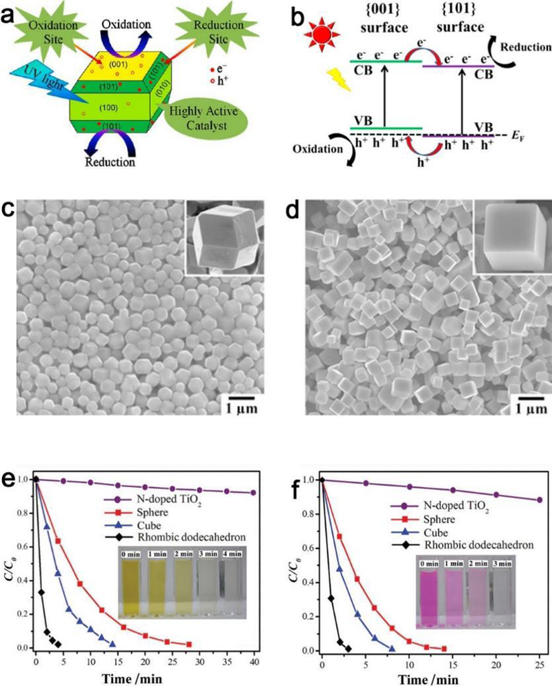
Shape & facet effect of photocatalysis. (a) Synergy of low-energy {101} and high-energy {001} TiO2 crystal facets for enhanced photocatalysis. (b) {001} and {101} surface heterojunction of TiO2. SEM images of (c) rhombic dodecahedrons and (d) cubic Ag3PO4 with different morphologies. The photocatalytic activities of Ag3PO4 rhombic dodecahedrons, cubes, spheres, and N-doped TiO2 are shown for the degradation of (e) MO and (f) RhB under visible light irradiation (λ > 400 nm). (a, b, c-f) Adapted with permission from refs 250, 251 and 260, copyright 2013, 2014 and 2011 American Chemical Society, respectively.
In addition, zinc oxide is an important semiconductor that has been widely applied in photocatalysis, whereas morphology control is an important approach to improve its photocatalytic performance. The ZnO tetrapods with different morphologies (nanoplates, nanorods) exhibit strong photocatalytic activities against methylene blue.252 Mesoporous and hexagon shaped ZnO nanodisks with exposed specific polar facets exhibit enhanced photovoltaic performance in QD sensitized solar cells.253 Anisotropic nanoplatelets can be used to engineer the heterojunction band structure and greatly improve the photocatalytic properties in a wide range by raising charge separation.254 ZnO rods/reduced graphene oxide composites showed high photocatalytic performances for efficient sunlight-driven photocatalysis, and the high specific surface of ZnO rods is one of the important reasons.255 Other anisotropic structures of metal oxides, such as Bi2O3 hierarchical nanostructures, also show excellent photocatalytic capabilities.256
It has also been reported that Ag and Au NPs with controlled geometry can affect the rate of photochemical reaction of adsorbed molecules.257–259 The shape and facet effects are also momentous for photocatalytic properties of single-crystalline Ag3PO4 crystals. Ag3PO4 rhombic dodecahedrons with only {110} facets exhibit much higher activities than that of cubes bounded entirely by {100} facets for the degradation of organic contaminants, which may be mainly ascribed to the higher surface energy of {110} facets than that of {100} facets (Figure 18c–f).260 Besides the above NPs, shape induced (spherical, sheets and rods) differences of photocatalytic activity also exist in CdS nanostructures for photodegradation of methylene blue dye under UV irradiation.261 In addition, high photocatalysis and visible light-induced charge retention are found with hybrid CdSe-Au nanodumbbells.262
4.2.2. Electrocatalysis
It is borne in mind that the catalytic reactivity of NPs increases proportionally with the number of metal atoms on the surface.263 Because of the massive surface area of NP dispersions, increasing their anisotropy can lead to a marked change in their catalytic activity. For example, Pt NPs of various shapes showed enhanced and selective catalytic performances over spherical NPs.264–266 Researches have explored a number of strategies to control the shape of Pt-based catalysts to obtain enhanced catalytic properties, including the yield of high-index facets and design of controlled architectures (e.g., textured, core-shell, or dendritic structure).47 Pd nanocrystals show structure-sensitive catalytic properties as well,45, 267–269 with the maximum current density of the formic acid oxidation increased in the order of octahedrons < truncated octahedrons < cuboctahedrons < truncated cubes < cubes, confirming that catalytic rate on Pd{100} was faster than that on Pd{111}.270 Taking into account their similar trend of anodic potential, Pd nanocubes with slightly truncated corners are the best catalyst for the oxidation of formic acid.
Electrochemical reduction of CO2 provides great potential for intermittent renewable energy storage. Liu and colleagues reported a predominant shape-dependent electrocatalytic reduction of CO2 to CO on triangular silver nanoplates (Tri-Ag-NPs).271 Tri-Ag-NPs showed an enhanced current density, considerably higher selectivity and significantly improved energy efficiency, together with a considerable durability compared with those of similarly sized Ag NPs and bulk Ag (Figure 19). Additionally, CO can be detected at an ultralow onset potential, indicating the excellent catalytic activity and superiority of Tri-Ag-NPs toward CO2RR. Density functional theory calculations (DFT) calculations revealed that the enhanced electrocatalytic activity and high selectivity of Tri-Ag-NPs at an ultralow overpotential is a consequence of the shape-controlled triangular structure, which provides both the optimum edge-to-corner ratio and the predominant Ag{100} facet. The above studies provide promising approaches to trim catalytic activity and selectivity of metal nanocatalysts via producing optimal facets and edge sites of specified shapes.
Figure 19.
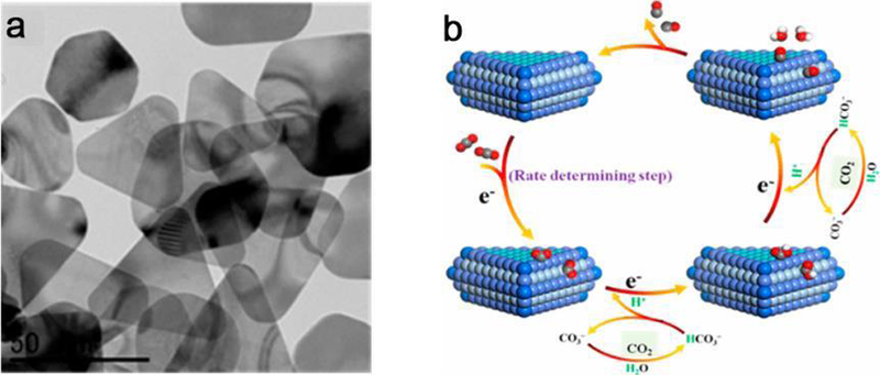
Shape-dependent electrocatalytic reduction of CO2 to CO on triangular silver nanoplates. (a) TEM image of triangular silver nanoplates (Tri-Ag-NPs), and (b) proposed mechanism for CO2RR to CO on Tri-Ag-NPs. Adapted with permission from ref 271, copyright 2017 American Chemical Society.
5. Biomedical applications
5.1. Fluorescence imaging
Fluorescence (and phosphorescence) based imaging has found particular interests and probably is one of the most widespread methods in various biomedical applications.272–275 The acquisition of fluorescence imaging usually is with the aid of fluorescent probes or nanomaterials, like semiconductor-nanoprobes (silicon-based nanostructures,276–278 carbon dots,279 semiconducting SWNTs and semiconducting sulfides280) and Au NPs,281 which can absorb and convert certain types of energy into radiation of visible light.57 As a result, trimming the morphology will contribute much to the fluorescence properties of the NPs-based probes. Among all kinds of fluorescent nanomaterials, QDs282–284 for visible light imaging and rare earth materials for upconversion bioimaging are the main representative and attractive candidates.
5.1.1. Visible light imaging
Fluorescent QDs are ideal fluorescence probes due to their narrow fluorescence line widths, shape (or size) tunable emission, photostability, and excitation with a single wavelength.285–288 Compared with spherical QDs, QRs with anisotropy could offer some superior properties such as larger absorption cross sections, faster radiative decay rates, linearly polarized emissions, more substantial Stokes shifts, and capability of functionalization at different sites with multiple binding moieties. These unique characteristics enable QRs promising materials with a wide range of applications, from biomedical imaging and biosensors to nanodevices. Yong et al. demonstrated that the tumor targeting and imaging in live animals could be achieved with functionalized semiconductor quantum nanocrystals with a rod shape.289 The highly luminescent CdSe/CdS/ZnS QRs can be successfully applied for targeted tumor fluorescence imaging, which is owing to conjugated cyclic RGD peptide binding to the αVβ3 integrins overexpressed in tumor vasculature. Hence, the optical imaging showed tumor sites in virtue of the accumulation of QR probes after systemic injection (Figure 20). In vivo tumor detection and cytotoxicity studies showed no adverse effects, indicating no toxicity in the cellular and tissue levels of functionalized QRs. As a result, they could be utilized as bright, photostable, and biocompatible luminescent probes for the early diagnosis of cancer. Likewise, another report suggested that the water-dispersible, noncytotoxic QRs in luminescence bioimaging can be fulfilled using silica-coating.290 It is also reported that dumbbell-shaped carbon quantum dots/Au NPs nanohybrid can be utilized as an efficient ratiometric fluorescent probe for sensing Cd2+ ions and L-ascorbic acid.291 The high sensitivity and selectivity of this dumbbell-shaped NPs ascribes to the static quenching and the inner filter effect. The addition of Cd2+ causes the formation of cubic aggregates, results in fast and complete fluorescence quenching of Au NCs. While in the presence of L-ascorbic acid, the above quenched sensor recovers gradually. Besides fluorescent QDs, it is reported that biocompatible Au nanoclusters (or Au dimers) with appropriate surface capping agent could also be employed as fluorescence contrast agents for live cell imaging.60, 292 The improvement of the photoluminescence yield is attributed to nanoparticle plasmons, particularly to the increase of scattering or absorption cross sections. Adjusting the shape or geometry of Au nanostructures allows a redshift in both the scattering and the photoluminescence spectra.
Figure 20.
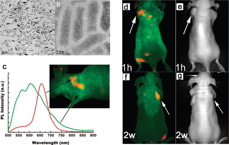
TEM images of CdSe/CdS/ZnS quantum rods (QRs) at a (a) low and (b) high magnification. The average length and width are 20.5 and 4.5 nm with an aspect ratio of 4.5. (c) The spectra of autofluorescence (green) and QR (red) of a nude mouse bearing tumor with QR bioconjugates. The signal of QR was obtained by subtracting the autofluorescence from the mixture. (d) In vivo luminescence imaging of Panc-1 tumor-bearing mice injected with cRGD-peptide-conjugated QRs of (d, e) 1 mg at 1 h and (f, g) 0.5 mg at 2 weeks, TEM images (right) corresponds to luminescence images (left), the tumor is indicated by white arrows. The autofluorescence of tumor-bearing mice is shown in green, and the unmixed QR signal in red. All images were acquired in the same experimental conditions. Reproduced with permission from ref 289, copyright 2009 American Chemical Society.
Besides metal-based NPs,293, 294 the shape effects also exist in organic nanostructures. Shao et al. reported that the micro/nanoaggregates with controlled morphologies (from rod to sphere) fabricated from organic quinoline–malononitrile (QM) derivatives can realize desirable far-red and NIR fluorescence and tumor-targeted bioimaging.295 The biocompatible QM nanoprobes are shape-tailored and preferable for cell-tracking and tumor-targeted bioimaging (Figure 21). Similarly, another study demonstrated the shape effect on aggregation-induced emission (AIE) probes for in vivo imaging by tuning their morphologies.296
Figure 21.
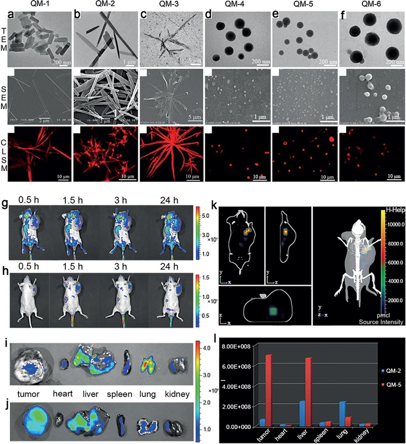
Multiple morphologies fabricated from quinoline–malononitrile (QM) derivatives. The TEM, SEM, and confocal laser scanning microscope images (from up to down) of (a) QM-1, (b) QM-2, (c) QM-3, (d) QM-4, (e) QM-5 and (f) QM-6, respectively. In vivo non-invasive imaging of mice bearing tumor after intravenous injection of (g) QM-2, (h) QM-5 at different time points (0.5, 1.5, 3 and 24 h), and fluorescence images of the organs of mice sacrificed at 24 h post-injection with (i) QM-2 and (j) QM-5. (k) The 3D fluorescence imaging of a tumor-bearing mice after intravenous injection of QM-5 for 24 h. (l) The distribution of average fluorescence intensity for tumor and internal organs from mice sacrificed at 24 h post-injection with QM-2 and QM-5 (n = 3). Adapted with permission from ref 295, copyright 2015 Wiley-VCH.
5.1.2. Upconversion bioimaging
Upconversion luminescence (UCL) is a nonlinear optical process, which usually converts NIR photons to short-wavelength emission.58 Recent advances in nanotechnology have promoted the development of upconversion nanomaterials as potential candidates of fluorescent probes for biomedical applications.297 In this area, it was found that anisotropic shaped NPs showed numerous applications for upconversion bioimaging.298–300 For example, lanthanide-doped NaGdF4 nanorods with multicolor photoluminescence301 and hexagonal-phase NaYF4:Yb,Er/Tm nanocrystals with controllable shape and upconversion fluorescence have been reported.302 The NaYF4:Yb3+/Er3+/Tm3+ nanoplates, nanospheres, and nanoellipses showed strong upconversion fluorescence and emitted varied fluorescence. The nanoplates showed stronger upconversion fluorescence emission compared to nanospheres and nanoellipses. It is possible that the nanoplates have a relatively large size and small surface and thus little surface defects, which are usually fluorescence quenchers. In addition, Murray et al. reported NaYF4-based spheres, nanorods, nanoplates, and nanoprisms and their tunable upconversion emissions.59 Besides engineering the dopant concentration, tuning the size or shape of anisotropic upconversion NPs is also an effective way to alter the upconversion luminescence. With increased size, both the total intensity of emission and the intensity ratio of green to red emission of NaYF4:Yb/Er NPs increased. This phenomenon can be attributed to the fact that the upconversion quenching caused by surface defects and ligands becomes more important with the decrease in size. On the other hand, the as-synthesized NaYF4:Yb/Ce/Ho spherical NPs and hexagonal nanoplates both displayed dominant red emission under the 980 nm excitation, but their total intensities of emission were much weaker than NPs with other shapes. These NPs hold great potential for the employment in biomedicine as fluorescent labels or imaging probes.
Zeng and co-workers achieved dual-modal X-ray and upconversion bioimaging by administering ligand-free NaLuF4:Gd/Yb/Er nanorods.303 In this work, the NaLuF4:Gd/Yb/Er nanorods exhibited enhanced visualization of blood vessels for in vivo synergistic X-ray imaging and UCL bioimaging of nude mice compared with that without nanorods (Figure 22). The nanorods also have excellent paramagnetism that can be employed as potential contrast agent for magnetic resonance imaging. These results indicate that the UCL nanorods could be utilized as promising candidates for angiography imaging and disease diagnosis. In addition, a series of core-shell UCL nanostructures are widely used in upconversion bioimaging as well.304–307
Figure 22.
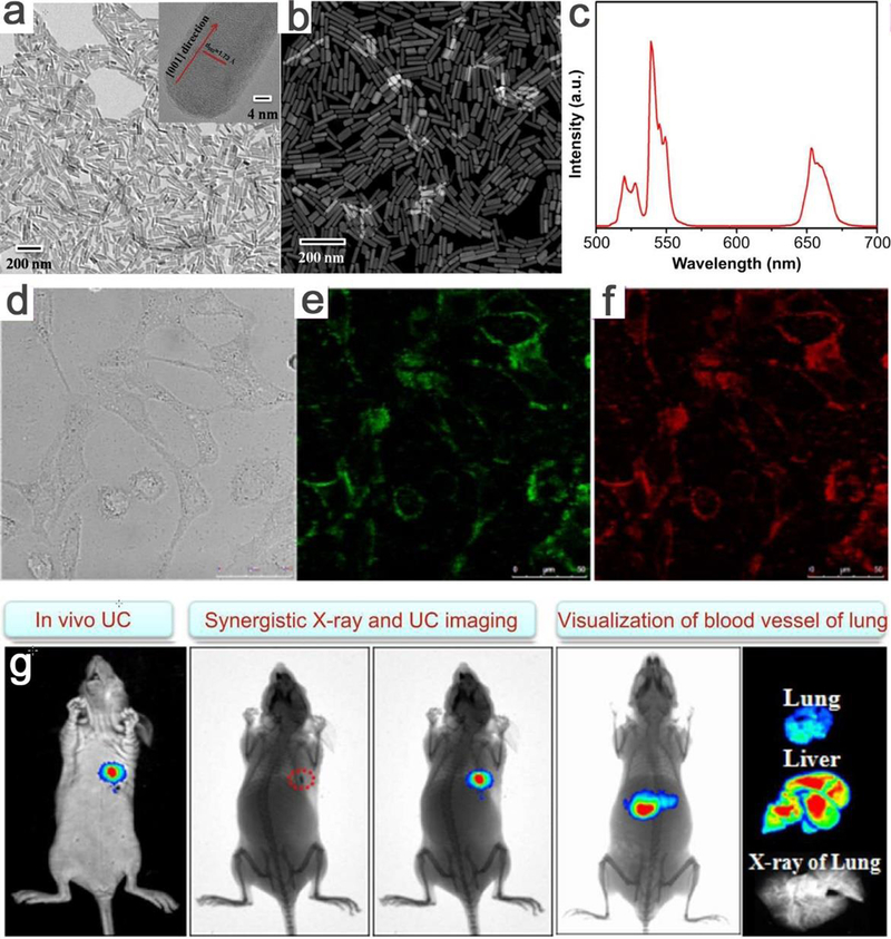
(a) The TEM image (insert: a corresponding HRTEM image of single nanorod) and (b) STEM image of NaLuF4:Gd/Yb/Er. (b) The upconversion spectra of OA-coated NaLuF4:Gd/Yb/Er nanorods under the excitation of 980 nm. (c) In vitro optical imaging of HeLa cells treated with NaLuF4:Gd/Yb/Er nanorods under 980 nm excitation, (d) bright field image, corresponding (e) green and (f) red upconversion fluorescent image. (g) Synergistical in vivo dual-modal X-ray and upconversion bioimaging of a nude mouse with subcutaneous injection of NaLuF4:Gd/Yb/Er nanorods. The ex-vivo upconversion bioimaging of lung, liver and X-ray imaging of lung of scarified nude mouse after 0.5 h intravenous injection with NaLuF4:Gd/Yb/Er nanorods. Adapted with permission from ref 303, copyright 2014 Elsevier Science.
5.2. Magnetic resonance imaging
Magnetic resonance imaging (MRI) has been extensively employed among numerous clinical diagnostic techniques during the past two decades due to its safety and high spatial resolution for soft tissues.308–310 MRI in some clinical trials require the use of contrast agents (CAs), which can accelerate the proton relaxation process of nearby water molecules under an external magnetic field, enhance the contrast between the detected region and background, and thus improve the sensitivity and accuracy.311–313 There are mainly three types of CAs, namely, T1 positive CAs for T1 imaging (e.g., Gd chelates, paramagnetic Gd2O3, MnO or NaGdF4 nanomaterials),314–318 T2 negative CAs for T2 imaging (e.g., superparamagnetic IO, ZnFe2O4 and Fe5C2 NPs),319–322 and T1-T2 CAs (e.g., EuIO, GdIO NPs)323–325 for T1-T2 dual modal imaging. Among them, the shape (morphology) plays a vital role in influencing T1 or T2 contrast enhancement effects in T1 and T2 imaging.326–328
5.2.1. T1 imaging
Conventional paramagnetic (e.g., Gd3+ or Mn2+) complexes-based T1 CAs are small molecules that are renal cleared within a few minutes, while NP-based T1 CAs could avoid this short circulation time.329, 330 Researchers can tailor the shapes of NP-based CAs to meet the biological requirements for optimizing T1 imaging. For example, Gd(III)-nanodiamond conjugates enable contrast enhancement for MRI compared to other agents.331 Ultrathin manganese oxide nanoplates exhibited strong MR contrast enhancement for in vivo T1 imaging derived from the large quantity of manganese ions exposed on the surface.332 Likewise, MnO nanotubes with more surface manganese ion density also showed larger r1 value compared to traditional manganese oxide nanospheres.333, 334 In a similar manner, Zhou et al. reported higher-performance T1 relaxivity of IO plates (Figure 23a–d)335 and GdIOP nanoplates (Figure 23e–g)336 compared to spheres ascribing to high ratios of surface metal (Fe or Gd) ions, which is a result of the geometrical shape confinement. Hence, the shape influences the T1 contrast effect due to the surface to volume ratio, because the exposed metal ions on the surface may provide efficient chemical exchange for protons and thus accelerate the T1 relaxation process. This theory is further demonstrated according to systematic and theoretical analyses of longitudinal relaxivities of ferrite oxides with different shapes (Figure 23h).337 In this work, the longitudinal relaxivity has positive correlations with surface-area to volume ratio and occupancy rate of effective metal ions on exposed surfaces of magnetic NPs.
Figure 23.
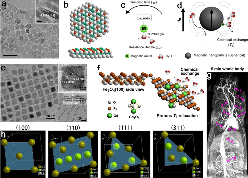
The effect of surface structure with different shapes on T1 contrast performance for NPs in T1 imaging. For IO plates, (a) TEM image of IO nanoplates with a thickness of 4.8 nm, (b) the distribution of atoms on the exposed Fe3O4 (111) facet, (c) main key parameters to T1 relaxation of protons, and (d) the proton interaction in a spherical magnetic NP system. For GdIOP nanoplates, (e) TEM and HRTEM images of vertically aligned GdIOP, (f) atomic side views of Fe3O4 (100) plane and Gd2O3 decorated surface for chemical exchange, and (g) the contrast-enhanced T1 MRA imaging of rats at 5 min after injection of GdIOP at 3.0 T with a dose of 0.2 mmol (Fe + Gd)/kg. (h) The exposed faces of (100), (110), (111), and (311) of MnIO NPs, showing different occupancy rates of metal ions on the surfaces. (a-d), (e-g) and (h) Reproduced with permission from ref 335, 336 and 337, copyright 2014, 2015 and 2018 American Chemical Society, respectively.
5.2.2. T2 imaging
The magnetic resonance signal in transverse relaxation process can be modulated with magnetic NPs in T2 imaging. Besides size,338 composition,339–341 and surface functionalization,62, 63 the shape also plays a critical role in determining the contrast abilities for T2 imaging. For T2 CAs, superparamagnetic IO establish a local perturbed dipolar field to shorten proton relaxation and increase signal difference of tissue and surrounding background. The local field inhomogeneity under an external magnetic field can be further elevated by artificially involving NPs with anisotropic geometries and shapes.342 For example, Zhao et al. reported that iron oxide NPs with octapod shape display an ultrahigh transverse relaxivity, and dramatically enhance the sensitivity of T2 imaging for early stage detection of cancer, due to the large effective radius and local field inhomogeneity of the magnetic core than the spheres (Figure 24a,b).88 This octapod shape was also well exploited in subsequent studies, such as ZnIO NPs343, 344 and CoIO NPs345, all these samples have high sensitivity and accuracy for sensitive CE-MRI. Furthermore, Yang et al. showed that magnetic ferrite oxide NPs with heterogeneous shapes (sphere, plate, tetrahedron, rhombohedron, and octapod, in Figure 24c) generate distinct stray fields and gradients under background field, affect the speed of efficient dephasing and diffusion process of surrounding protons, determine effective radii together with saturated magnetizations of particle, and finally affect transverse relaxation rates and in vivo liver and tumor T2-weighted imaging performance (Figure 24 d–i).337
Figure 24.
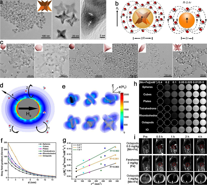
The effect of morphology on T2 contrast performance for NPs in T2 imaging. For pure IO octapods, (a) TEM images in low and high magnifications and HRTEM image of a trigonal pyramidal arm with IO Octapod-30, (b) schematic illustration shows the effective radius of octapod is 2.4 times of spheres with the same geometric volume under an external magnetic field of B0. For ferrite oxides, (c) TEM images of ferrite oxides of different morphologies with the same geometric volume, (d) scheme of water molecular diffusion and proton relaxation process around spherical magnetic NPs, (e) spatial distributions of stray fields of different shapes along the longest diagonal at an external magnetic field H0, (f) changes of stray field gradients with different shapes, (g) the linear relationship of the ratio of r2 value to the square of saturated magnetization (r2/Ms2) and the square of effective radius (r*), (h) T2-weighted phantom images of ferrite oxides with multiple shapes measured at 1.5 T MRI, and (h) in vivo T2-weighted MRI of liver tumor in sagittal plane and liver in transverse plane of mice at 7.0 T. The scale bars in (a) are 100 nm, 20 nm and 2 nm, respectively. All scale bars in (c) is 100 nm. (a-b) Adapted with permission from ref 88, copyright 2013 Nature Publishing Group. (c-i) Reproduced with permission from ref 337, copyright 2018 American Chemical Society.
5.3. Photothermal therapy
Killing tumor cells by photothermal therapy relies on hyperthermia, which is a condition that cells are subjected to heat (above 42 °C) for tens of minutes. It will cause irreversible damage to the cells due to destruction of cell membranes and/or denaturing of proteins.346, 347 Nanomaterials such as Au NPs can absorb and convert electromagnetic energy into heat by photothermal effect348, 349 and have high tumor specificity due to their ability to accumulate in tumor site through passive targeting and/or active targeting enabled by ligands.350
Shape also has a profound effect on Au NPs-based application in photothermal therapy. West and Halas proved the selective photothermal ablation of SKBR3 breast cancer cells of Au nanorods conjugated with anti-HER2 antibody.351 Li et al. demonstrated the effective photothermal ablation of melanoma tumors by applying melanocyte-stimulating hormone conjugated hollow Au nanospheres.352 Song et al. reported ultrasmall Au nanorod vesicles have an enhanced tumor accumulation and fast excretion from the body for cancer therapy.353 These Au nanorods vesicles could accomplish rapid excretion from the body due to the degradation into small nanorods by hydrolysis of the coated PLGA, enhanced photothermal properties by the strong interparticle plasmonic coupling, prominent tumor accumulation and high photothermal cancer therapy efficacy (Figure 25). In another case, glutathione-responsive self-assembled Au NPs could be applied for enhanced tumor imaging and imaging-guided photothermal therapy with a nanowreath shape, which caused improved photothermal properties compared to Au seeds and/or thick Au nanoring with smooth surface due to the presence of Au branches, small junctions, and central holes in Au nanowreaths.354 In this work, the GSH-responsive self-assembled magnetic Au nanowreaths have a NIR absorption, resulting in strong photoacoustic signal and effective photoablation of tumor for imaging-guided photothermal therapy.
Figure 25.
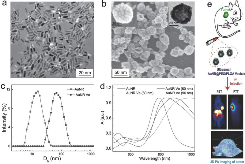
(a) The TEM image of small Au nanorods (about 8 nm × 2 nm). (b) The SEM image of small plasmonic Au NR@PEG/PLGA vesicles, insets are SEM and TEM images of Au vesicle at a large magnification. (c) The hydrodynamic diameter distribution of Au NR and Au NR vesicles. (d) The UV–vis spectra of Au NR and Au NR vesicles with different sizes (60, 80, and 96 nm) in water. (e) The schematic illustration of Au vesicles with prominent tumor accumulation and enhanced photoacoustic and photothermal cancer therapy efficacy. Adapted by permission from ref 353, copyright 2015 Wiley-VCH.
Besides the discussed materials, Kim et al. utilized golden carbon nanotubes as multimodal photoacoustic and photothermal high-contrast molecular agents.355 Li and co-workers reported CuTe nanocrystal with different shapes (nanocubes, nanoplates, and nanorods) that have different plasmonic properties as photothermal agents.356 Morphology of polymer nanovehicle also plays a significant role. It was reported that molecular bottlebrush-based unimolecular micelle with tunable morphologies including sphere, rod, worm or core-shell structures, could offer different bio-behaviors and effects on inhibiting tumor growth for photothermal cancer therapy.21
6. Biological behaviours
Shape factors (morphology, geometry or anisotropy) of NPs have an influence on particle-cell interactions. For instance, the radius of curvature is crucial in determining the amount and rate of particle phagocytosis. Anisotropic geometry also influences the in vitro behaviors like cytotoxicity, cell uptake and in vivo behaviors, such as biocompatibility, targeting ability, biodistribution and clearance of NPs.
6.1. In vitro behaviours
6.1.1. Cytotoxicity
The NPs-mediated cytotoxicity is known to be affected by several factors, cell surface, colloidal stability, particle uptake and other physicochemical factors.357 The anisotropy or geometry can influence the quantity of particles ingested. Too high ratio of NPs uptake could disrupt cellular functions and bring about adverse cytotoxic effect, which induces excessive endocytosis and results in oxidative stress-mediated mitochondrial damage.358
Though the relationships between cytotoxicity and shapes are not obvious,359, 360 their correlation does exist in many studies indeed. For example, investigations of the toxicity of mesoporous silica nanorods claimed shape-dependent cytotoxicity in A549 human lung epithelial cells and RAW 264.7 murine macrophages.361 Hemolysis assay indicated that the hemolytic activity is geometry-dependent for bare SiO2. Hamilton et al. studied the cytotoxicity of TiO2 NPs with different aspect ratios using primary mouse C57BL/6 lung macrophages, and found a higher cytotoxicity for larger nanofibers among the tested spherical, short and long nanofibers.362 In this work, the long nanofibers incubated with alveolar macrophages led to the release of cathepsin B (a lysosomal protease) and the disruption of the lysosomal membrane, resulting in drastically increased levels of interleukin-1 and interleukin-18, suggesting the particle length-dependent inflammatory response. Similarly, Stoehr et al. indicated the cytotoxicity of high aspect ratio silver NPs in A549 cells, silver nanowires showed shape-dependent toxicity compared to nanospheres (Figure 26).363 Another report suggested the high aspect ratios of carbon nanotubes cause frustrated phagocytosis and result in inflammation and systemic effects.364 Additionally, geometry or anisotropy of NPs can also affect cytoskeletal organization,365–368 induce disruption of lipid bilayers and cytotoxic and pro-inflammatory responses.
Figure 26.
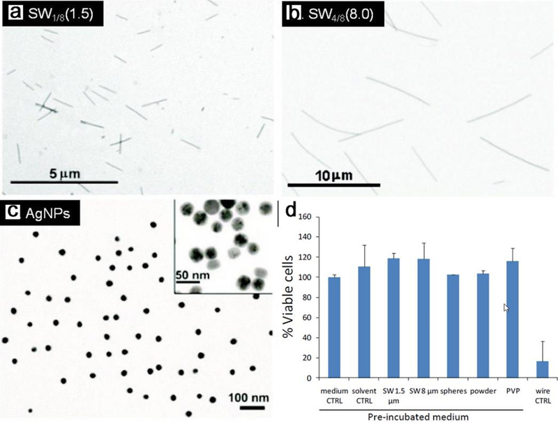
(a) The TEM image of silver nanowires with lengths of (a) 1.5 μm and (b) 8.0 μm, and (c) spherical Ag NPs of 30 nm. (d) Cell viability and cytotoxic effects of A549 cells using CellTiter Blue®. NPs were incubated in cell culture medium for 48 hours at 37 °C and 5% CO2. After centrifugation the supernatants were added onto A549 cells and incubated for another 48 hours. Adapted by permission from ref 363, copyright 2011 Springer Nature.
6.1.2. Shape-dependent cell uptake
The cell uptake of NPs has attracted considerable attention, one reason is that NPs could be applied as vehicles for intracellular drug delivery. It is well-known that cell uptake of NPs is determined by an intricate interplay of physicochemical properties like shape, size, and surface functionalization, and the effect of shape is extensively investigated in recent years. For instance, Xie et al. reported the shape effect on cellular uptake of methylpolyethylene glycol coated Au NPs in the forms of stars, rods, and triangles by RAW264.7 cells.369 The efficiency of cellular uptake from low to high follows the order of stars, rods, and triangles. Their results demonstrated that shape can modulate the cellular uptake of NPs, and different shapes were inclined to undergo various endocytosis pathways in different proportions. Similarly, shape dependence of Au NPs uptake into mammalian cells were demonstrated between rods with different aspect ratios and spheres.370
Another report investigated the uptake behaviors of fluorescently labeled spherical and non-spherical NPs with equal volume by qualitative and quantitative analysis.25 Uptake of NPs in MSC and HeLa cells have a negative correlation between aspect ratio and uptake rate, showing non-spherical NPs with less cellular uptake than the spherical counterparts (Figure 27). This phenomenon can be attributed to the larger average curvature radius of non-spherical particles. In a similar report, shape and orientation matter for the cellular uptake of non-spherical NPs were studied, providing systematic understanding for membrane wrapping of NPs, viruses, and bacterial forms.24 Stable endocytic states with small and high wrapping fraction is favorable for rod-like NPs, a submarine mode is tended for high aspect ratios and round tips, and a rocket mode is likely for small aspect ratios and flat tips. In addition, Wang et al. have also shown that the DNA-functionalized nanoflowers can be readily taken by cells.371
Figure 27.
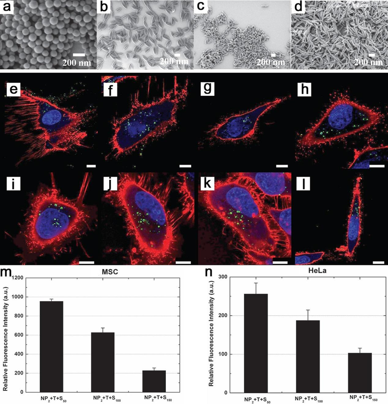
SEM micrographs of (a) NP2+T-S0, (b) NP2+T+S50, (c) NP2+T+S100 and (d) NP2+T+S150. NPi, NPi+T+S (NPs with temperature treatment and stretching) and NPi+T-S (NPs with temperature treatment and without stretching). Corresponding uptake of (a-d) into (e–h) MSC-cells and (i–l) HeLa-cells after 20 h of incubation at a concentration of 75 μg mL-1. Particles (in green), cell membrane (in red), and cell nuclei (in blue). Scale bar is 10 μm. Uptake of NPs with different aspect ratios in (m) MSC and (n) HeLa cells of NP2+T+S50, NP2+T+S100 and NP2+T+S150. Adapted by permission from ref 25, copyright 2012 Wiley-VCH.
The findings in these studies will give implications in the chemical design of NPs in biomedical applications (e.g., tuning intracellular delivery rates), and provide useful guidelines for the design of NPs for drug delivery.
6.2. In vivo behaviours
6.2.1. Biocompatibility
Conventional problems of biocompatibility of NPs in vivo stem from the fact that toxicity is influenced by particle physicochemical properties like shape effects. Inhalation of high aspect ratio fibers leads to frustrated phagocytosis of pulmonary macrophages, which can result in poor biocompatibility such as asbestosis, bronchogenic carcinoma, pleural fibrosis, mesothelioma, and pleural plaque formation.364, 372 Compared to traditional spherical NPs, long fibers also cause more recruitment of polymorphonuclear leukocytes, exotic body giant cells, and other pathology. For example, after injection into the peritoneal cavity of female C57BL/6 mice with carbon nanotubes of various lengths, granulomatous inflammation was found through histological analysis of diaphragms.373 However, other reports suggested that systemic toxicity caused by intravenous administration of high aspect ratio CNT is not palpable, acute systemic toxicity could be mitigated with proper coatings like PEG/phospholipid.374–376 Similarly, intravenous injection of PEGylated carbon nanotubes showed no significant toxicity in nude mice.377 The long-term biocompatibility is tied to particle biodistribution, in vivo fate (i.e., excretion), and degradation, and these will be discussed in latter parts in this review.
6.2.2. Targeting ability
NPs generally distribute throughout the body after intravenous injection, thus optimizing factors such as particle shape can help particles accumulate or target to the sites where need to be introduced. NPs have been considered as ideal tools on nanotechnology platforms to deliver drugs for cancer therapy due to their ability to target tumors by passive or active targeting (small molecule, aptamer or antibody targeting).378 The nonspecific targeting mechanism relies on the “enhanced permeability and retention” (EPR) of NPs that are allowed to enter the tumor interstitial space due to the enhanced permeability of the tumor vasculature and the suppressed lymphatic filtration.379, 380 Whereas, shape of particle still in part dictates the passive particle localization at tumor sites despite the mechanism of EPR effect.
For example, Kolhar et al. demonstrated that rod shaped NPs exhibit higher specific and lower nonspecific accumulation at the target tissue compared to their spherical ones.381 Mathematical modeling of particle–surface interactions reveals that the higher specificity and avidity of nanorods generated from the balance of polyvalent interactions, which promotes adhesion, entropic losses and shear–induced detachment. The shape–specific tissue accumulation and shape–induced enhancement of vascular targeting is also observed in brain and lungs for NPs coupled with anti–intracellular adhesion molecules and anti–transferrin receptor antibodies (Figure 28).
Figure 28.
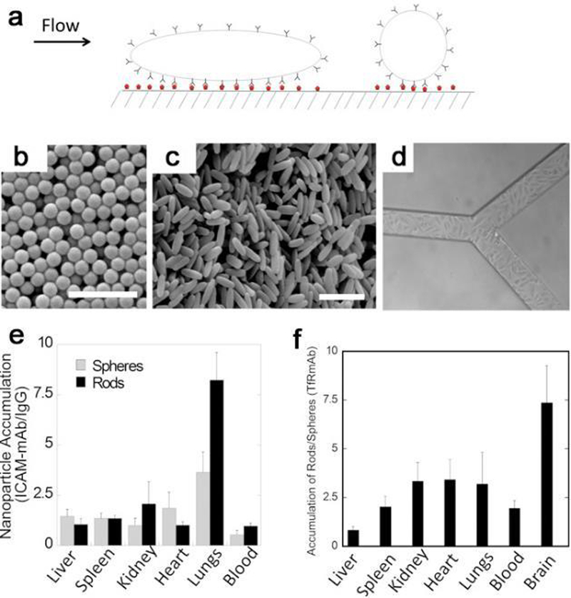
Shape–effects on targeting and biodistribution of NPs under flow. (a) Schematic of NPs with different shapes interacting with a wall under flow. (b) SEM images of (b) polystyrene spheres and (c) elongated particles stretched from (a). Scale bar is 1 μm. (d) RBE4 cells-laden synthetic microvascular networks. Ratio of (e) ICAM-mAb–coated NPs to IgG–coated NPs for rods (in black) and spheres (in gray) and (f) TfR-mAb–coated rods to spheres (n = 3–5). Adapted with permission from ref 381, copyright 2013 National Academy of Sciences.
Targeted delivery of therapeutic agents in the vascular compartment is a significant issue for treating hemorrhage, thrombosis, and atherosclerosis. Platelets have an inherent ability of vascular injury site-directed margination, site-specific adhesion, and amplification of injury site-specific aggregation, and these functions can be tuned by their shapes. In this regard, Anselmo et al. fabricated platelet-like NPs (PLNs) to target vascular injuries and enable hemostatic functions with the biochemical and biophysical designs such as mimicking shape and surface biology.382 The PLNs displayed enhanced surface-binding compared with their spherical and rigid discoidal counterparts, together with site-selective adhesion and platelet-aggregation properties. In vivo studies indicated that PLNs targeted at the wound site and led to ∼65% reduction in bleeding time, effectively attained the hemostatic functions of natural platelets (Figure 29).
Figure 29.
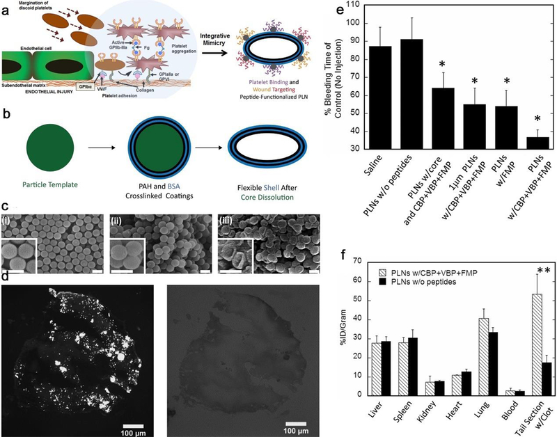
(a) Schematic showing platelet interactions in hemostasis and corresponding platelet-inspired design. (b) Illustration of the platelet-like NPs (PLNs) synthesis to two bilayers of PAH/BSA. (c) SEM of (i) sacrificial 200 nm spherical and (ii) (PAH/BSA)4-coated polystyrene templates, (iii) final PLNs. Scale bar is 200 nm. (d) Brightfield and fluorescent images of tail section clot. (e) Hemostatic effect of PLNs in a tail amputation model in mice. (f) Biodistributions in organ with plain PLNs or PLNs functionalized with CBP+VBP+FMP at 1 h after tail amputation. Adapted with permission from ref 382, copyright 2014 American Chemical Society.
Another example is Au NPs (20 nm spheres, 40 nm spheres, 40 nm cubes, and 36 nm × 10 nm rods) have been investigated as effective vaccine adjuvants in vivo for West Nile virus. In this work the shape played a role in enhancing immune response via different cytokine pathways.383 Moreover, Chauhan et al. reported that nanorods exhibited superior transport and distribution into mammary tumors to nanospheres of similar plasma half‐life in vivo.384 The nanorods with the smallest diameter or longest aspect ratio showed the highest concentration of doxorubicin in tumor and lower amounts in spleen, liver, and lungs due to the more effective escape of NPs from the reticuloendothelial system with a smaller diameter. Likewise, filomicelle-paclitaxel showed significant inhibition of tumor growth in mice bearing A549 xenograft tumors compared to spherical paclitaxel NPs or free drug.385
6.2.3. Biodistribution and clearance
Understanding how shape affects the biodistribution of intravenously injected NPs is of fundamental importance for the rational design of delivery systems. There have been numerous studies of the in vivo biodistribution behaviours of anisotropic NPs. Huang et al. reported the biodistribution of silica NPs in mice post intravenous administration,386 short nanorods with an aspect ratio of 1.5 accumulated more in the liver whereas long nanorods with an aspect ratio of 5 localized more in the spleen. Yu et al. investigated the mucosal penetration of mesoporous silica spheres and rods, and the rod-shaped silica NPs were shown to penetrate and accumulate more in small intestines compared to spherical ones.387 The shape advantage for nanorods than spheres are dictated by the porosity of the mucus as well as the shape-induced diffusion of anisotropic nanorods.
Another study investigated the organ distribution of spherical, quasi-hemispherical, cylindrical and discoidal silicon NPs after intravenous injection into MDA-MB-231 tumor bearing female mice.388 Cylindrical NPs were deposited at a larger extent in the liver, while discoidal NPs were observed to accumulate significantly more in the lungs and heart than the cylindrical, hemispherical, or spherical NPs, which may be because of the margination propensity of discoidal particles resulting in the accumulation of NPs on vascular walls. Likewise, plate-like Au doped NPs were also shown to accumulate in heart and lungs (Figure 30).389 In another similar research, Godin et al. confirmed that discoidal mesoporous silica NPs accumulated up to five times more than spherical counterparts with a similar diameter in breast tumors.390 NPs can also accumulate in hair follicles or skin folds after transporting through the stratum corneum. Transfollicular delivery of ovalbumin by using polymeric NPs could bring about a significant cellular and humoral immune response without compromising the stratum corneum barrier.391–393
Figure 30.
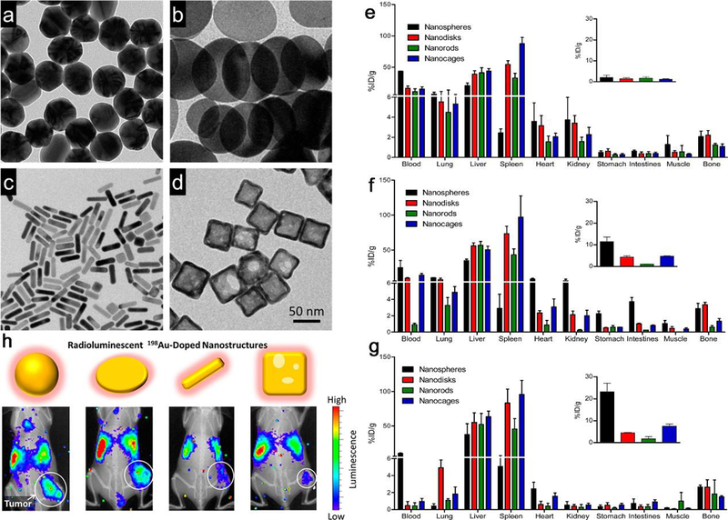
TEM images of (a) nanospheres, (b) nanodisks, (c) nanorods, and (d) cubic nanocages Au NPs. The scale bar applies to all images. Biodistribution of the different types of 198Au-doped Au NPs at (e) 1 h, (f) 6 h, and (g) 24 h after injection, insets are the tumor uptake data. (h) Co-registered X-ray and in vivo luminescence images of the tumor-bearing mice at 24 h post-injection of different types of 198Au-incorporated NPs. From left to right is nanospheres, nanodisks, nanorods, and cubic nanocages, respectively. Reproduced with permission from ref 389, copyright 2014 American Chemical Society.
Investigating the circulation time in vivo and clearance of NPs with the consideration of the shape affect is significant for their biomedical applications. It appears that NPs with higher aspect ratios prolong circulation time in vivo. It was reported that filamentous micelles made from amphiphilic block copolymers had significantly longer circulation time than that of their spherical ones.394 Other reports further supported this result that higher aspect ratio NPs hold longer circulation time.395 For instance, Au nanorods persisted significantly more in circulation compared to spherical NPs.396 This is due to the extension by the flow and accumulation next to the vessel walls for larger particles with high aspect ratios, together with the uniform radial distribution and limited near-wall accumulation for smaller particles.394, 397 The clearance of NPs with anisotropic shapes is incomparably complicated when it comes to different morphologies, such as discoidal/plate-like NPs are also shown to accumulate in heart and lungs due to margination under flow.388, 389 Some of them appear to be similarly governed by diameter (or length) in circulation. While most of particulate matters will be trapped and cleared by the reticuloendothelial system (RES), NPs with high aspect ratio tend to be filtered out by the spleen, when the particles are larger than 200 nm.398–400 NPs with diameter between 15 and 200 nm tend to accumulate and be cleared by the liver, which has a large coverage of the majority of anisotropic NPs.401 And small NPs less than 10 nm can reach various organs by crossing the tight endothelial junctions and be rapidly cleared via glomerular filtration by the kidneys and excreted to the urine.402–404 Evidence also suggests that some high aspect ratio NPs can also be filtered via the kidneys when the cross-sectional diameter is small enough to pass through the glomerular pore.405
7. Summary and Prospects
Initially, anisotropic NPs attracted interests from scientific communities due to their fascinating catalytic, optical, electrical, or magnetic properties. Subsequently, it was discovered that distinctive shapes of these NPs could potentially dictate their various applications as well as interactions with single cells and ultimately whole organisms. This review summarizes the most recent researches on anisotropic NPs-based materials in their specific physicochemical and biomedical applications, including optics, catalysis, imaging, and therapy. A systematic understanding of these NPs from mechanism, synthesis, property to application as well as their in vitro and in vivo biological behaviors are discussed. We have witnessed a fairly remarkable progress in manipulating anisotropic NPs for their exciting potential physicochemical and biomedical applications in the last two decades. Despite these incredible accomplishments, anisotropic NPs still face lots of major challenges that need to be addressed before they can be eventually employed in industrial or biomedical applications.
For the synthesis, as the literatures with regard to fabrication of anisotropic NPs reported in this review continue to expand, the basis for experimental design is evolving from empirical rules towards well‐established scientific theory. Delicate control has been achieved, nevertheless, there is still a long way to go to plenarily understand all the complexities involved in this charming science. For example, the scale up production of anisotropic NPs is one of the major challenges as many anisotropic nanomaterials were only realized at a lab scale. Actually, many different kinds of shaped NP addressed in this review could not be facilely scaled up such as the preparation of octopods with a good magnetite crystal structure. Although it is obviously important to make efforts to scale up synthesis of NPs, therapeutic gains from such anisotropic materials and costs of these endeavors must be taken into account. Therefore, there should be focuses on economical and comprehensive designs as well as efforts towards the scalable production of anisotropic NPs in the future.
For catalysis and optics, catalyst NP with unique shape exposes one or one group of specific crystallographic surface. This crystallographic surface consists of certain surface atoms with specific electronic state and induced shape-dependent catalytic performance, which has been well-demonstrated in literature. It should be notable that the shape-dependent catalytic performance on nanocatalyst is commonly related to different coordination environment of catalyst atoms on facets, resulting in definite activity and selectivity. Anisotropy can also impart particular optical property and enhance the imaging capability of material, for instance, SERS sensing with gold nanostars. These unique optical characteristics with anisotropic NPs provide strategies for further developments in ultrasensitive imaging.
For biobehaviour and biomedicine, we should keep in mind that fundamental studies on the shape effect in the NP-biological interaction is incomplete to date. Particularly for the uptake, anisotropic NPs are preferentially endocytosed by most cell types when the diameter is larger than 100 nm, while at smaller scales the consequence of shape on the uptake of NPs is contentious. It appears that NPs with high aspect ratios are favorably endocytosed compared with other shapes, whereas, the different surface chemistry has a disproportionately stronger effect. More characterization data, such as colloidal stability and polydispersity, may explain the contradictions in previously published reports in some way. Although the question that how shape impacts the in vitro and in vivo behaviors has no simple answer in this review, it is encouraging that there are several principles can guide the design of future NPs for biomedical applications. Researchers can take full advantage of these findings to manufacture NPs for fluorescence imaging, photothermal therapy and MRI. However, we must be aware of that there is also an overdependence on recording final outcomes to show the successful utility of NPs for biomedical applications. Many researches did not perform full pharmacokinetics and biodistribution analyses of the administered anisotropic NPs, nor did they confirm that NPs actually target the cells of tissues or tumors in vivo.
Finally, we hope this review will not only give researchers a more comprehensive understanding of anisotropic NPs and their characteristic properties or applications, but also provide necessary insights, full thinking, and directional strategies for designing their own experiments, as well as open new horizons for scientists in the future physicochemical and biomedical applications.
Acknowledgements
This research was supported by National Natural Science Foundation of China (NSFC) projects (Grant number: 201874024), and the intramural research program of the National Institute of Biomedical Imaging and Bioengineering (NIBIB), National Institutes of Health (NIH).
Footnotes
Conflicts of interest
The authors declare no competing financial interest.
References:
- 1.Pedone D, Moglianetti M, De Luca E, Bardi G and Pompa PP, Chem. Soc. Rev, 2017, 46, 4951–4975. [DOI] [PubMed] [Google Scholar]
- 2.Zhou W, Gao X, Liu D and Chen X, Chem. Rev, 2015, 115, 10575–10636. [DOI] [PMC free article] [PubMed] [Google Scholar]
- 3.Fan Z and Zhang H, Acc. Chem. Res, 2016, 49, 2841–2850. [DOI] [PubMed] [Google Scholar]
- 4.Shen L, Yu L, Wu HB, Yu X-Y, Zhang X and Lou XW, Nat. Commun, 2015, 6, 6694. [DOI] [PubMed] [Google Scholar]
- 5.Wall MA, Harmsen S, Pal S, Zhang L, Arianna G, Lombardi JR, Drain CM and Kircher MF, Adv. Mater, 2017, 29. [DOI] [PMC free article] [PubMed] [Google Scholar]
- 6.Liao H-G, Jiang Y-X, Zhou Z-Y, Chen S-P and Sun S-G, Angew. Chem, 2008, 47, 9100–9103. [DOI] [PubMed] [Google Scholar]
- 7.Liu H, Li W, Shen D, Zhao D and Wang G, J. Am. Chem. Soc, 2015, 137, 13161–13166. [DOI] [PubMed] [Google Scholar]
- 8.Chen S, Wang ZL, Ballato J, Foulger SH and Carroll DL, J. Am. Chem. Soc, 2003, 125, 16186–16187. [DOI] [PubMed] [Google Scholar]
- 9.Zeng J, Zheng Y, Rycenga M, Tao J, Li Z-Y, Zhang Q, Zhu Y and Xia Y, J. Am. Chem. Soc, 2010, 132, 8552–8553. [DOI] [PubMed] [Google Scholar]
- 10.Bu L, Zhang N, Guo S, Zhang X, Li J, Yao J, Wu T, Lu G, Ma J-Y, Su D and Huang X, Science, 2016, 354, 1410. [DOI] [PubMed] [Google Scholar]
- 11.Zhou Z, Zhu X, Wu D, Chen Q, Huang D, Sun C, Xin J, Ni K and Gao J, Chem. Mater, 2015, 27, 3505–3515. [Google Scholar]
- 12.Yin X-L, Li L-L, Jiang W-J, Zhang Y, Zhang X, Wan L-J and Hu J-S, ACS Appl. Mater. Interfaces, 2016, 8, 15258–15266. [DOI] [PubMed] [Google Scholar]
- 13.Zhao N, Wei Y, Sun N, Chen Q, Bai J, Zhou L, Qin Y, Li M and Qi L, Langmuir, 2008, 24, 991–998. [DOI] [PubMed] [Google Scholar]
- 14.Rodríguez-Lorenzo L, de la Rica R, Álvarez-Puebla RA, Liz-Marzán LM and Stevens MM, Nat. Mater, 2012, 11, 604. [DOI] [PubMed] [Google Scholar]
- 15.Kinnear C, Moore TL, Rodriguez-Lorenzo L, Rothen-Rutishauser B and Petri-Fink A, Chem. Rev, 2017, 117, 11476–11521. [DOI] [PubMed] [Google Scholar]
- 16.Rodríguez-Lorenzo L, Álvarez-Puebla RA, de Abajo FJG and Liz-Marzán LM, J. Phys. Chem. C, 2010, 114, 7336–7340. [Google Scholar]
- 17.Dondapati SK, Sau TK, Hrelescu C, Klar TA, Stefani FD and Feldmann J, ACS Nano, 2010, 4, 6318–6322. [DOI] [PubMed] [Google Scholar]
- 18.Peiris PM, Toy R, Doolittle E, Pansky J, Abramowski A, Tam M, Vicente P, Tran E, Hayden E, Camann A, Mayer A, Erokwu BO, Berman Z, Wilson D, Baskaran H, Flask CA, Keri RA and Karathanasis E, ACS Nano, 2012, 6, 8783–8795. [DOI] [PMC free article] [PubMed] [Google Scholar]
- 19.Fan Z, Senapati D, Singh AK and Ray PC, Mol. Pharm, 2013, 10, 857–866. [DOI] [PMC free article] [PubMed] [Google Scholar]
- 20.Lacroix L-M, Frey Huls N, Ho D, Sun X, Cheng K and Sun S, Nano Lett, 2011, 11, 1641–1645. [DOI] [PubMed] [Google Scholar]
- 21.Li H, Liu H, Nie T, Chen Y, Wang Z, Huang H, Liu L and Chen Y, Biomaterials, 2018, 178, 620–629. [DOI] [PubMed] [Google Scholar]
- 22.Pietuch A, Schneider D, Rother J, Sunnick E, Rosman C, Pierrat S, Sönnichsen C, Wegener J and Janshoff A, Nanotoxicology, 2011, 5, 254–268. [DOI] [PubMed] [Google Scholar]
- 23.Heng BC, Zhao X, Tan EC, Khamis N, Assodani A, Xiong S, Ruedl C, Ng KW and Loo JS-C, Arch. Toxicol, 2011, 85, 1517–1528. [DOI] [PubMed] [Google Scholar]
- 24.Dasgupta S, Auth T and Gompper G, Nano Lett, 2014, 14, 687–693. [DOI] [PubMed] [Google Scholar]
- 25.Florez L, Herrmann C, Cramer JM, Hauser CP, Koynov K, Landfester K, Crespy D and Mailänder V, Small, 2012, 8, 2222–2230. [DOI] [PubMed] [Google Scholar]
- 26.Huang X, Peng X, Wang Y, Wang Y, Shin DM, El-Sayed MA and Nie S, ACS Nano, 2010, 4, 5887–5896. [DOI] [PMC free article] [PubMed] [Google Scholar]
- 27.Carnovale C, Bryant G, Shukla R and Bansal V, Prog. Mater. Sci, 2016, 83, 152–190. [Google Scholar]
- 28.Chu Z, Zhang S, Zhang B, Zhang C, Fang C-Y, Rehor I, Cigler P, Chang H-C, Lin G, Liu R and Li Q, Sci. Rep, 2014, 4, 4495. [DOI] [PMC free article] [PubMed] [Google Scholar]
- 29.Tian F, Clift MJ, Casey A, Pino P. d., Pelaz B, Conde J, Byrne HJ, Rothen-Rutishauser B, Estrada G, Fuente J. M. d. l. and Stoeger T, Nanomedicine, 2015, 10, 2643–2657. [DOI] [PubMed] [Google Scholar]
- 30.Wang H, Feng J, Liu G, Chen B, Jiang Y and Xie Q, Nanomed. Nanotechnol. Biol. Med, 2016, 12, 881–891. [DOI] [PubMed] [Google Scholar]
- 31.Albanese A, Tang PS and Chan WCW, Annu. Rev. Biomed. Eng, 2012, 14, 1–16. [DOI] [PubMed] [Google Scholar]
- 32.Pelaz B, Alexiou C, Alvarez-Puebla RA, Alves F, Andrews AM, Ashraf S, Balogh LP, Ballerini L, Bestetti A, Brendel C, Bosi S, Carril M, Chan WCW, Chen C, Chen X, Chen X, Cheng Z, Cui D, Du J, Dullin C, Escudero A, Feliu N, Gao M, George M, Gogotsi Y, Grünweller A, Gu Z, Halas NJ, Hampp N, Hartmann RK, Hersam MC, Hunziker P, Jian J, Jiang X, Jungebluth P, Kadhiresan P, Kataoka K, Khademhosseini A, Kopeček J, Kotov NA, Krug HF, Lee DS, Lehr C-M, Leong KW, Liang X-J, Ling Lim M, Liz-Marzán LM, Ma X, Macchiarini P, Meng H, Möhwald H, Mulvaney P, Nel AE, Nie S, Nordlander P, Okano T, Oliveira J, Park TH, Penner RM, Prato M, Puntes V, Rotello VM, Samarakoon A, Schaak RE, Shen Y, Sjöqvist S, Skirtach AG, Soliman MG, Stevens MM, Sung H-W, Tang BZ, Tietze R, Udugama BN, VanEpps JS, Weil T, Weiss PS, Willner I, Wu Y, Yang L, Yue Z, Zhang Q, Zhang Q, Zhang X-E, Zhao Y, Zhou X and Parak WJ, ACS Nano, 2017, 11, 2313–2381. [DOI] [PMC free article] [PubMed] [Google Scholar]
- 33.Shi J, Kantoff PW, Wooster R and Farokhzad OC, Nat. Rev. Cancer, 2016, 17, 20. [DOI] [PMC free article] [PubMed] [Google Scholar]
- 34.Burda C, Chen X, Narayanan R and El-Sayed MA, Chem. Rev, 2005, 105, 1025–1102. [DOI] [PubMed] [Google Scholar]
- 35.Maier SA, Brongersma ML, Kik PG, Meltzer S, Requicha AAG and Atwater HA, Adv. Mater, 2001, 13, 1501–1505. [Google Scholar]
- 36.Yin AX, Liu WC, Ke J, Zhu W, Gu J, Zhang YW and Yan CH, J. Am. Chem. Soc, 2012, 134, 20479–20489. [DOI] [PubMed] [Google Scholar]
- 37.Butet J, Thyagarajan K and Martin OJF, Nano Lett, 2013, 13, 1787–1792. [DOI] [PubMed] [Google Scholar]
- 38.Halas NJ, Lal S, Chang W-S, Link S and Nordlander P, Chem. Rev, 2011, 111, 3913–3961. [DOI] [PubMed] [Google Scholar]
- 39.Prodan E, Radloff C, Halas NJ and Nordlander P, Science, 2003, 302, 419–422. [DOI] [PubMed] [Google Scholar]
- 40.Kelly KL, Coronado E, Zhao LL and Schatz GC, The Journal of Physical Chemistry B, 2003, 107, 668–677. [Google Scholar]
- 41.Xia Y, Xiong Y, Lim B and Skrabalak SE, Angew. Chem. Int. Ed, 2009, 48, 60–103. [DOI] [PMC free article] [PubMed] [Google Scholar]
- 42.Tao AR, Habas S and Yang P, Small, 2008, 4, 310–325. [Google Scholar]
- 43.Ray PC, Chem. Rev, 2010, 110, 5332–5365. [DOI] [PMC free article] [PubMed] [Google Scholar]
- 44.Hua Y, Chandra K, Dam DHM, Wiederrecht GP and Odom TW, J. Phys. Chem. Lett, 2015, 6, 4904–4908. [DOI] [PubMed] [Google Scholar]
- 45.Zhang H, Jin M, Xiong Y, Lim B and Xia Y, Acc. Chem. Res, 2013, 46, 1783–1794. [DOI] [PubMed] [Google Scholar]
- 46.Narayanan R and El-Sayed MA, J. Phys. Chem. B, 2005, 109, 12663–12676. [DOI] [PubMed] [Google Scholar]
- 47.Wang YJ, Zhao N, Fang B, Li H, Bi XT and Wang H, Chem. Rev, 2015, 115, 3433–3467. [DOI] [PubMed] [Google Scholar]
- 48.Cao S, Tao FF, Tang Y, Li Y and Yu J, Chem. Soc. Rev, 2016, 45, 4747–4765. [DOI] [PubMed] [Google Scholar]
- 49.Chen J, Lim B, Lee EP and Xia Y, Nano Today, 2009, 4, 81–95. [Google Scholar]
- 50.Yan Y, Du JS, Gilroy KD, Yang D, Xia Y and Zhang H, Adv. Mater, 2017, 29. [DOI] [PubMed] [Google Scholar]
- 51.Fernández EM, Moses PG, Toftelund A, Hansen HA, Martínez JI, Abild-Pedersen F, Kleis J, Hinnemann B, Rossmeisl J, Bligaard T and Nørskov JK, Angew. Chem. Int. Ed, 2008, 47, 4683–4686. [DOI] [PubMed] [Google Scholar]
- 52.Nørskov JK, Bligaard T, Hvolbæk B, Abild-Pedersen F, Chorkendorff I and Christensen CH, Chem. Soc. Rev, 2008, 37, 2163–2171. [DOI] [PubMed] [Google Scholar]
- 53.Falsig H, Shen J, Khan TS, Guo W, Jones G, Dahl S and Bligaard T, Top. Catal, 2014, 57, 80–88. [Google Scholar]
- 54.Liu P, Qin R, Fu G and Zheng N, J. Am. Chem. Soc, 2017, 139, 2122–2131. [DOI] [PubMed] [Google Scholar]
- 55.Li L-S, Walda J, Manna L and Alivisatos AP, Nano Lett, 2002, 2, 557–560. [Google Scholar]
- 56.Mokari T and Banin U, Chem. Mater, 2003, 15, 3955–3960. [Google Scholar]
- 57.Ntziachristos V, Nat. Methods, 2010, 7, 603. [DOI] [PubMed] [Google Scholar]
- 58.Gai S, Li C, Yang P and Lin J, Chem. Rev, 2014, 114, 2343–2389. [DOI] [PubMed] [Google Scholar]
- 59.Ye X, Collins JE, Kang Y, Chen J, Chen DT, Yodh AG and Murray CB, Proc. Natl. Acad. Sci. U. S. A, 2010, 107, 22430–22435. [DOI] [PMC free article] [PubMed] [Google Scholar]
- 60.Polavarapu L, Manna M and Xu QH, Nanoscale, 2011, 3, 429–434. [DOI] [PubMed] [Google Scholar]
- 61.Carroll MR, Woodward RC, House MJ, Teoh WY, Amal R, Hanley TL and St Pierre TG, Nanotechnology, 2010, 21, 035103. [DOI] [PubMed] [Google Scholar]
- 62.Tromsdorf UI, Bigall NC, Kaul MG, Bruns OT, Nikolic MS, Mollwitz B, Sperling RA, Reimer R, Hohenberg H, Parak WJ, Forster S, Beisiegel U, Adam G and Weller H, Nano Lett, 2007, 7, 2422–2427. [DOI] [PubMed] [Google Scholar]
- 63.Hao R, Xing R, Xu Z, Hou Y, Gao S and Sun S, Adv. Mater, 2010, 22, 2729–2742. [DOI] [PubMed] [Google Scholar]
- 64.Laurent S, Forge D, Port M, Roch A, Robic C, Vander Elst L and Muller RN, Chem. Rev, 2008, 108, 2064–2110. [DOI] [PubMed] [Google Scholar]
- 65.Hancock RD and Martell AE, Chem. Rev, 1989, 89, 1875–1914. [Google Scholar]
- 66.Chan WCW, Acc. Chem. Res, 2017, 50, 627–632. [DOI] [PubMed] [Google Scholar]
- 67.Sun Y and Xia Y, Science, 2002, 298, 2176–2179. [DOI] [PubMed] [Google Scholar]
- 68.Owen J, Science, 2015, 347, 615–616. [DOI] [PubMed] [Google Scholar]
- 69.Chen M, Wu B, Yang J and Zheng N, Adv. Mater, 2012, 24, 862–879. [DOI] [PubMed] [Google Scholar]
- 70.Rose MK, Mitsui T, Dunphy J, Borg A, Ogletree DF, Salmeron M and Sautet P, Surf. Sci, 2002, 512, 48–60. [Google Scholar]
- 71.Huang X, Tang S, Mu X, Dai Y, Chen G, Zhou Z, Ruan F, Yang Z and Zheng N, Nat. Nanotechnol, 2010, 6, 28. [DOI] [PubMed] [Google Scholar]
- 72.Pan Y-T, Yin X, Kwok KS and Yang H, Nano Lett, 2014, 14, 5953–5959. [DOI] [PubMed] [Google Scholar]
- 73.Yin X, Liu X, Pan Y-T, Walsh KA and Yang H, Nano Lett, 2014, 14, 7188–7194. [DOI] [PubMed] [Google Scholar]
- 74.Zhao L, Xu C, Su H, Liang J, Lin S, Gu L, Wang X, Chen M and Zheng N, Adv. Sci, 2015, 2, 1500100. [DOI] [PMC free article] [PubMed] [Google Scholar]
- 75.Wu B, Zheng N and Fu G, Chem. Commun, 2011, 47, 1039–1041. [DOI] [PubMed] [Google Scholar]
- 76.Chen G, Tan Y, Wu B, Fu G and Zheng N, Chem. Commun, 2012, 48, 2758–2760. [DOI] [PubMed] [Google Scholar]
- 77.Kang Y, Ye X and Murray CB, Angew. Chem, 2010, 122, 6292–6295. [Google Scholar]
- 78.Dai Y, Mu X, Tan Y, Lin K, Yang Z, Zheng N and Fu G, J. Am. Chem. Soc, 2012, 134, 7073–7080. [DOI] [PubMed] [Google Scholar]
- 79.Habas SE, Lee H, Radmilovic V, Somorjai GA and Yang P, Nat. Mater, 2007, 6, 692. [DOI] [PubMed] [Google Scholar]
- 80.Huang X, Zhao Z, Fan J, Tan Y and Zheng N, J. Am. Chem. Soc, 2011, 133, 4718–4721. [DOI] [PubMed] [Google Scholar]
- 81.Niu Z and Li Y, Chem. Mater, 2013, 26, 72–83. [Google Scholar]
- 82.Personick ML and Mirkin CA, J. Am. Chem. Soc, 2013, 135, 18238–18247. [DOI] [PubMed] [Google Scholar]
- 83.Sun SB, Yuan D, Xu Y, Wang AF and Deng ZT, ACS Nano, 2016, 10, 3648–3657. [DOI] [PubMed] [Google Scholar]
- 84.Meyns M, Iacono F, Palencia C, Geweke J, Coderch MD, Fittschen UEA, Gallego JM, Otero R, Juarez BH and Klinke C, Chem. Mater, 2014, 26, 1813–1821. [Google Scholar]
- 85.Zhang Y, Grass ME, Kuhn JN, Tao F, Habas SE, Huang W, Yang P and Somorjai GA, J. Am. Chem. Soc, 2008, 130, 5868–5869. [DOI] [PubMed] [Google Scholar]
- 86.Carrasquillo A, Jeng J-J, Barriga RJ, Temesghen WF and Soriaga MP, Inorg. Chim. Acta, 1997, 255, 249–254. [Google Scholar]
- 87.Huang X, Zhang H, Guo C, Zhou Z and Zheng N, Angew. Chem. Int. Ed, 2009, 48, 4808–4812. [DOI] [PubMed] [Google Scholar]
- 88.Zhao Z, Zhou Z, Bao J, Wang Z, Hu J, Chi X, Ni K, Wang R, Chen X, Chen Z and Gao J, Nat. Commun, 2013, 4, 2266. [DOI] [PubMed] [Google Scholar]
- 89.Lohse SE, Burrows ND, Scarabelli L, Liz-Marzán LM and Murphy CJ, Chem. Mater, 2013, 26, 34–43. [Google Scholar]
- 90.Jin M, He G, Zhang H, Zeng J, Xie Z and Xia Y, Angew. Chem. Int. Ed, 2011, 50, 10560–10564. [DOI] [PubMed] [Google Scholar]
- 91.Ye X, Chen J, Engel M, Millan JA, Li W, Qi L, Xing G, Collins JE, Kagan CR, Li J, Glotzer SC and Murray CB, Nat. Chem, 2013, 5, 466. [DOI] [PubMed] [Google Scholar]
- 92.Pourmasoud S, Sobhani-Nasab A, Behpour M, Rahimi-Nasrabadi M and Ahmadi F, J. Mol. Struct, 2018, 1157, 607–615. [Google Scholar]
- 93.Kovalenko MV, Bodnarchuk MI, Lechner RT, Hesser G, Schaffler F and Heiss W, J. Am. Chem. Soc, 2007, 129, 6352–6353. [DOI] [PubMed] [Google Scholar]
- 94.Park J, An K, Hwang Y, Park J-G, Noh H-J, Kim J-Y, Park J-H, Hwang N-M and Hyeon T, Nat. Mater, 2004, 3, 891. [DOI] [PubMed] [Google Scholar]
- 95.Zhang L, Wu J, Liao H, Hou Y and Gao S, Chem. Commun, 2009, 4378–4380. [DOI] [PubMed] [Google Scholar]
- 96.Liu D, Xu X, Du Y, Qin X, Zhang Y, Ma C, Wen S, Ren W, Goldys EM, Piper JA, Dou S, Liu X and Jin D, Nat. Commun, 2016, 7, 10254. [DOI] [PMC free article] [PubMed] [Google Scholar]
- 97.Kim M-S, Lim S, Chaudhari NK, Fang B, Bae T-S and Yu J-S, Catal. Today, 2010, 158, 354–360. [Google Scholar]
- 98.Shimazaki Y, Kobayashi Y, Yamada S, Miwa T and Konno M, J. Colloid Interface Sci, 2005, 292, 122–126. [DOI] [PubMed] [Google Scholar]
- 99.Abedini A, Daud AR, Abdul Hamid MA, Kamil Othman N and Saion E, Nanoscale Res. Lett, 2013, 8, 474. [DOI] [PMC free article] [PubMed] [Google Scholar]
- 100.Rusnaeni N, Purwanto WW, Nasikin M and Hendrajaya L, J. Appl. Sci, 2010, 10, 2899–2904. [Google Scholar]
- 101.Fang B, Chaudhari NK, Kim MS, Kim JH and Yu JS, J. Am. Chem. Soc, 2009, 131, 15330–15338. [DOI] [PubMed] [Google Scholar]
- 102.Xue C and Mirkin CA, Angew. Chem. Int. Ed, 2007, 46, 2036–2038. [DOI] [PubMed] [Google Scholar]
- 103.Li G, Peng C, Zhang C, Xu Z, Shang M, Yang D, Kang X, Wang W, Li C, Cheng Z and Lin J, Inorg. Chem, 2010, 49, 10522–10535. [DOI] [PubMed] [Google Scholar]
- 104.Singh B and Dempsey E, ECS J. Solid State Sci. Technol, 2012, 1, M25–M32. [Google Scholar]
- 105.Sheng W, Lee SW, Crumlin EJ, Chen S and Shao-Horn Y, J. Electrochem. Soc, 2011, 158, B1398–B1404. [Google Scholar]
- 106.Chandan A, Hattenberger M, El-kharouf A, Du S, Dhir A, Self V, Pollet BG, Ingram A and Bujalski W, J. Power Sources, 2013, 231, 264–278. [Google Scholar]
- 107.Watt J, Yu C, Chang SL, Cheong S and Tilley RD, J. Am. Chem. Soc, 2013, 135, 606–609. [DOI] [PubMed] [Google Scholar]
- 108.Li Z and Peng X, J. Am. Chem. Soc, 2011, 133, 6578–6586. [DOI] [PubMed] [Google Scholar]
- 109.Guo S, Fidler AF, He K, Su D, Chen G, Lin Q, Pietryga JM and Klimov VI, J. Am. Chem. Soc, 2015, 137, 15074–15077. [DOI] [PubMed] [Google Scholar]
- 110.Xia Y, Xia X and Peng HC, J. Am. Chem. Soc, 2015, 137, 7947–7966. [DOI] [PubMed] [Google Scholar]
- 111.Tsung CK, Kou X, Shi Q, Zhang J, Yeung MH, Wang J and Stucky GD, J. Am. Chem. Soc, 2006, 128, 5352–5353. [DOI] [PubMed] [Google Scholar]
- 112.Nikoobakht B and El-Sayed MA, Chem. Mater, 2003, 15, 1957–1962. [Google Scholar]
- 113.Jana NR, Gearheart L and Murphy CJ, Adv. Mater, 2001, 13, 1389–1393. [Google Scholar]
- 114.Chen L, Huang B, Qiu X, Wang X, Luque R and Li Y, Chem. Sci, 2016, 7, 228–233. [DOI] [PMC free article] [PubMed] [Google Scholar]
- 115.Xia Y, Gilroy KD, Peng HC and Xia X, Angew. Chem. Int. Ed, 2017, 56, 60–95. [DOI] [PubMed] [Google Scholar]
- 116.Pietrobon B, McEachran M and Kitaev V, ACS Nano, 2009, 3, 21–26. [DOI] [PubMed] [Google Scholar]
- 117.Sun Y, Yin Y, Mayers BT, Herricks T and Xia Y, Chem. Mater, 2002, 14, 4736–4745. [Google Scholar]
- 118.Zhang Q, Li W, Moran C, Zeng J, Chen J, Wen LP and Xia Y, J. Am. Chem. Soc, 2010, 132, 11372–11378. [DOI] [PMC free article] [PubMed] [Google Scholar]
- 119.Sanchez-Iglesias A, Winckelmans N, Altantzis T, Bals S, Grzelczak M and Liz-Marzan LM, J. Am. Chem. Soc, 2017, 139, 107–110. [DOI] [PubMed] [Google Scholar]
- 120.Tangeysh B, Moore Tibbetts K, Odhner JH, Wayland BB and Levis RJ, Nano Lett, 2015, 15, 3377–3382. [DOI] [PubMed] [Google Scholar]
- 121.Zhou G, Yang Y, Han S, Chen W, Fu Y, Zou C, Zhang L and Huang S, ACS Appl. Mater. Interfaces, 2013, 5, 13340–13352. [DOI] [PubMed] [Google Scholar]
- 122.Gilroy KD, Yang X, Xie S, Zhao M, Qin D and Xia Y, Adv. Mater, 2018, 30, 1706312. [DOI] [PubMed] [Google Scholar]
- 123.Luo M, Ruditskiy A, Peng H-C, Tao J, Figueroa-Cosme L, He Z and Xia Y, Adv. Funct. Mater, 2016, 26, 1209–1216. [Google Scholar]
- 124.S. R. Lee, J. Park, K. D. Gilroy, X. Yang, L. Figueroa-Cosme, Y. Ding and Y. Xia, ChemCatChem, 2016, 8, 3082–3088. [Google Scholar]
- 125.Coropceanu I, Rossinelli A, Caram JR, Freyria FS and Bawendi MG, ACS Nano, 2016, 10, 3295–3301. [DOI] [PubMed] [Google Scholar]
- 126.Weiner RG, DeSantis CJ, Cardoso MB and Skrabalak SE, ACS Nano, 2014, 8, 8625–8635. [DOI] [PubMed] [Google Scholar]
- 127.Sun S, Zeng H, Robinson DB, Raoux S, Rice PM, Wang SX and Li G, J. Am. Chem. Soc, 2004, 126, 273–279. [DOI] [PubMed] [Google Scholar]
- 128.Song Q and Zhang ZJ, J. Am. Chem. Soc, 2004, 126, 6164–6168. [DOI] [PubMed] [Google Scholar]
- 129.Liu Y, Tang A, Zhang Q and Yin Y, J. Am. Chem. Soc, 2015, 137, 11327–11339. [DOI] [PubMed] [Google Scholar]
- 130.Martin CR, Science, 1994, 266, 1961–1966. [DOI] [PubMed] [Google Scholar]
- 131.Thomas A, Goettmann F and Antonietti M, Chem. Mater, 2008, 20, 738–755. [Google Scholar]
- 132.Lee W, Ji R, Gösele U and Nielsch K, Nat. Mater, 2006, 5, 741. [DOI] [PubMed] [Google Scholar]
- 133.Wu Y, Livneh T, Zhang YX, Cheng G, Wang J, Tang J, Moskovits M and Stucky GD, Nano Lett, 2004, 4, 2337–2342. [Google Scholar]
- 134.Wu Y, Cheng G, Katsov K, Sides SW, Wang J, Tang J, Fredrickson GH, Moskovits M and Stucky GD, Nat. Mater, 2004, 3, 816. [DOI] [PubMed] [Google Scholar]
- 135.Xia Y, Yang P, Sun Y, Wu Y, Mayers B, Gates B, Yin Y, Kim F and Yan H, Adv. Mater, 2003, 15, 353–389. [Google Scholar]
- 136.Lee MH, Lin JY and Odom TW, Angew. Chem. Int. Ed, 2010, 49, 3057–3060. [DOI] [PubMed] [Google Scholar]
- 137.Fredriksson H, Alaverdyan Y, Dmitriev A, Langhammer C, Sutherland DS, Zäch M and Kasemo B, Adv. Mater, 2007, 19, 4297–4302. [Google Scholar]
- 138.Henzie J, Lee MH and Odom TW, Nat. Nanotechnol, 2007, 2, 549. [DOI] [PubMed] [Google Scholar]
- 139.Yang JC, Gao H, Suh JY, Zhou W, Lee MH and Odom TW, Nano Lett, 2010, 10, 3173–3178. [DOI] [PMC free article] [PubMed] [Google Scholar]
- 140.Chen CL and Rosi NL, Angew. Chem. Int. Ed, 2010, 49, 1924–1942. [DOI] [PubMed] [Google Scholar]
- 141.George J and Thomas KG, J. Am. Chem. Soc, 2010, 132, 2502–2503. [DOI] [PubMed] [Google Scholar]
- 142.Guli M, Lambert EM, Li M and Mann S, Angew. Chem, 2010, 122, 530–533. [DOI] [PubMed] [Google Scholar]
- 143.Carter CJ, Ackerson CJ and Feldheim DL, ACS Nano, 2010, 4, 3883–3888. [DOI] [PMC free article] [PubMed] [Google Scholar]
- 144.Jones MR, Osberg KD, Macfarlane RJ, Langille MR and Mirkin CA, Chem. Rev, 2011, 111, 3736–3827. [DOI] [PubMed] [Google Scholar]
- 145.Gunawidjaja R, Peleshanko S, Ko H and Tsukruk VV, Adv. Mater, 2008, 20, 1544–1549. [Google Scholar]
- 146.Lee J, Govorov AO, Dulka J and Kotov NA, Nano Lett, 2004, 4, 2323–2330. [Google Scholar]
- 147.Li JF, Huang YF, Ding Y, Yang ZL, Li SB, Zhou XS, Fan FR, Zhang W, Zhou ZY, Wu DY, Ren B, Wang ZL and Tian ZQ, Nature, 2010, 464, 392. [DOI] [PubMed] [Google Scholar]
- 148.Lu CL, Prasad KS, Wu HL, Ho JA and Huang MH, J. Am. Chem. Soc, 2010, 132, 14546–14553. [DOI] [PubMed] [Google Scholar]
- 149.Wu X, Redmond PL, Liu H, Chen Y, Steigerwald M and Brus L, J. Am. Chem. Soc, 2008, 130, 9500–9506. [DOI] [PubMed] [Google Scholar]
- 150.Xia X, Wang Y, Ruditskiy A and Xia Y, Adv. Mater, 2013, 25, 6313–6333. [DOI] [PubMed] [Google Scholar]
- 151.Wang Z, Luan D, Li CM, Su F, Madhavi S, Boey FY and Lou XW, J. Am. Chem. Soc, 2010, 132, 16271–16277. [DOI] [PubMed] [Google Scholar]
- 152.Skrabalak SE, Chen J, Sun Y, Lu X, Au L, Cobley CM and Xia Y, Acc. Chem. Res, 2008, 41, 1587–1595. [DOI] [PMC free article] [PubMed] [Google Scholar]
- 153.Gonzalez E, Arbiol J and Puntes VF, Science, 2011, 334, 1377–1380. [DOI] [PubMed] [Google Scholar]
- 154.Gu H, Yang Z, Gao J, Chang CK and Xu B, J. Am. Chem. Soc, 2005, 127, 34–35. [DOI] [PubMed] [Google Scholar]
- 155.Yu H, Chen M, Rice PM, Wang SX, White RL and Sun S, Nano Lett, 2005, 5, 379–382. [DOI] [PubMed] [Google Scholar]
- 156.Liu H and Alivisatos AP, Nano Lett, 2004, 4, 2397–2401. [Google Scholar]
- 157.Bai H, Xu K, Xu Y and Matsui H, Angew. Chem. Int. Ed, 2007, 46, 3319–3322. [DOI] [PubMed] [Google Scholar]
- 158.Keren K, Krueger M, Gilad R, Ben-Yoseph G, Sivan U and Braun E, Science, 2002, 297, 72–75. [DOI] [PubMed] [Google Scholar]
- 159.Keren K, Berman RS, Buchstab E, Sivan U and Braun E, Science, 2003, 302, 1380–1382. [DOI] [PubMed] [Google Scholar]
- 160.Tan YN, Lee JY and Wang DI, J. Am. Chem. Soc, 2010, 132, 5677–5686. [DOI] [PubMed] [Google Scholar]
- 161.Slocik JM and Naik RR, Adv. Mater, 2006, 18, 1988–1992. [Google Scholar]
- 162.Kasyutich O, Ilari A, Fiorillo A, Tatchev D, Hoell A and Ceci P, J. Am. Chem. Soc, 2010, 132, 3621–3627. [DOI] [PubMed] [Google Scholar]
- 163.Leroux F, Gysemans M, Bals S, Batenburg KJ, Snauwaert J, Verbiest T, Van Haesendonck C and Van Tendeloo G, Adv. Mater, 2010, 22, 2193–2197. [DOI] [PubMed] [Google Scholar]
- 164.Balci S, Noda K, Bittner AM, Kadri A, Wege C, Jeske H and Kern K, Angew. Chem. Int. Ed, 2007, 46, 3149–3151. [DOI] [PubMed] [Google Scholar]
- 165.Eisele DM, Berlepsch HV, Bottcher C, Stevenson KJ, Vanden Bout DA, Kirstein S and Rabe JP, J. Am. Chem. Soc, 2010, 132, 2104–2105. [DOI] [PubMed] [Google Scholar]
- 166.Cushing BL, Kolesnichenko VL and O’Connor CJ, Chem. Rev, 2004, 104, 3893–3946. [DOI] [PubMed] [Google Scholar]
- 167.Wang X, Zhuang J, Peng Q and Li Y, Nature, 2005, 437, 121. [DOI] [PubMed] [Google Scholar]
- 168.Radi A, Pradhan D, Sohn Y and Leung KT, ACS Nano, 2010, 4, 1553–1560. [DOI] [PubMed] [Google Scholar]
- 169.Xue C, Millstone JE, Li S and Mirkin CA, Angew. Chem. Int. Ed, 2007, 46, 8436–8439. [DOI] [PubMed] [Google Scholar]
- 170.Zhang J, Li S, Wu J, Schatz GC and Mirkin CA, Angew. Chem. Int. Ed, 2009, 48, 7787–7791. [DOI] [PMC free article] [PubMed] [Google Scholar]
- 171.Langille MR, Zhang J and Mirkin CA, Angew. Chem. Int. Ed, 2011, 50, 3543–3547. [DOI] [PubMed] [Google Scholar]
- 172.Zhang H, Xia X, Li W, Zeng J, Dai Y, Yang D and Xia Y, Angew. Chem, 2010, 122, 5424–5428. [DOI] [PubMed] [Google Scholar]
- 173.Linic S, Christopher P, Xin H and Marimuthu A, Acc. Chem. Res, 2013, 46, 1890–1899. [DOI] [PubMed] [Google Scholar]
- 174.Ma Y, Li W, Cho EC, Li Z, Yu T, Zeng J, Xie Z and Xia Y, ACS Nano, 2010, 4, 6725–6734. [DOI] [PMC free article] [PubMed] [Google Scholar]
- 175.Linic S, Christopher P and Ingram DB, Nat. Mater, 2011, 10, 911–921. [DOI] [PubMed] [Google Scholar]
- 176.Butet J, Brevet PF and Martin OJ, ACS Nano, 2015, 9, 10545–10562. [DOI] [PubMed] [Google Scholar]
- 177.Albella P, Garcia-Cueto B, Gonzalez F, Moreno F, Wu PC, Kim TH, Brown A, Yang Y, Everitt HO and Videen G, Nano Lett, 2011, 11, 3531–3537. [DOI] [PubMed] [Google Scholar]
- 178.Song J, Wu B, Zhou Z, Zhu G, Liu Y, Yang Z, Lin L, Yu G, Zhang F, Zhang G, Duan H, Stucky GD and Chen X, Angew. Chem. Int. Ed, 2017, 56, 8110–8114. [DOI] [PubMed] [Google Scholar]
- 179.Zhang H and Govorov AO, J. Phys. Chem. C, 2014, 118, 7606–7614. [Google Scholar]
- 180.Yang M, Alvarez-Puebla R, Kim HS, Aldeanueva-Potel P, Liz-Marzan LM and Kotov NA, Nano Lett, 2010, 10, 4013–4019. [DOI] [PMC free article] [PubMed] [Google Scholar]
- 181.Li W, Zamani R, Rivera Gil P, Pelaz B, Ibáñez M, Cadavid D, Shavel A, Alvarez-Puebla RA, Parak WJ, Arbiol J and Cabot A, J. Am. Chem. Soc, 2013, 135, 7098–7101. [DOI] [PubMed] [Google Scholar]
- 182.Talley CE, Jackson JB, Oubre C, Grady NK, Hollars CW, Lane SM, Huser TR, Nordlander P and Halas NJ, Nano Lett, 2005, 5, 1569–1574. [DOI] [PubMed] [Google Scholar]
- 183.Boyack R and Le Ru EC, Phys. Chem. Chem. Phys, 2009, 11, 7398–7405. [DOI] [PubMed] [Google Scholar]
- 184.Zhu Z, Meng H, Liu W, Liu X, Gong J, Qiu X, Jiang L, Wang D and Tang Z, Angew. Chem. Int. Ed, 2011, 50, 1593–1596. [DOI] [PubMed] [Google Scholar]
- 185.Fan W, Lee YH, Pedireddy S, Zhang Q, Liu T and Ling XY, Nanoscale, 2014, 6, 4843–4851. [DOI] [PubMed] [Google Scholar]
- 186.Liu W, Zhu Z, Deng K, Li Z, Zhou Y, Qiu H, Gao Y, Che S and Tang Z, J. Am. Chem. Soc, 2013, 135, 9659–9664. [DOI] [PubMed] [Google Scholar]
- 187.Kundu S, J. Mater. Chem. C, 2013, 1, 831–842. [Google Scholar]
- 188.Park JE, Lee Y and Nam JM, Nano Lett, 2018, 18, 6475–6482. [DOI] [PubMed] [Google Scholar]
- 189.Hong JW, Lee SU, Lee YW and Han SW, J. Am. Chem. Soc, 2012, 134, 4565–4568. [DOI] [PubMed] [Google Scholar]
- 190.Zhang L-F, Zhong S-L and Xu A-W, Angew. Chem, 2013, 125, 673–677. [Google Scholar]
- 191.Ye X, Jin L, Caglayan H, Chen J, Xing G, Zheng C, Doan-Nguyen V, Kang Y, Engheta N, Kagan CR and Murray CB, ACS Nano, 2012, 6, 2804–2817. [DOI] [PubMed] [Google Scholar]
- 192.Jana NR, Gearheart L and Murphy CJ, J. Phys. Chem. B, 2001, 105, 4065–4067. [Google Scholar]
- 193.Chen H, Shao L, Li Q and Wang J, Chem. Soc. Rev, 2013, 42, 2679–2724. [DOI] [PubMed] [Google Scholar]
- 194.Chang WS, Ha JW, Slaughter LS and Link S, Proc. Natl. Acad. Sci. U. S. A, 2010, 107, 2781–2786. [DOI] [PMC free article] [PubMed] [Google Scholar]
- 195.Qu Y, Cheng R, Su Q and Duan X, J. Am. Chem. Soc, 2011, 133, 16730–16733. [DOI] [PMC free article] [PubMed] [Google Scholar]
- 196.Okuno Y, Nishioka K, Kiya A, Nakashima N, Ishibashi A and Niidome Y, Nanoscale, 2010, 2, 1489–1493. [DOI] [PubMed] [Google Scholar]
- 197.Vanmaekelbergh D, van Vugt LK, Bakker HE, Rabouw FT, de Nijs B, van Dijk-Moes RJA, van Huis MA, Baesjou PJ and van Blaaderen A, ACS Nano, 2015, 9, 3942–3950. [DOI] [PubMed] [Google Scholar]
- 198.Jiang P, Zhu C-N, Zhang Z-L, Tian Z-Q and Pang D-W, Biomaterials, 2012, 33, 5130–5135. [DOI] [PubMed] [Google Scholar]
- 199.Zhang B, Wang Y, Yang C, Hu S, Gao Y, Zhang Y, Wang Y, Demir HV, Liu L and Yong K-T, Phys. Chem. Chem. Phys, 2015, 17, 25133–25141. [DOI] [PubMed] [Google Scholar]
- 200.Xu G, Zeng S, Zhang B, Swihart MT, Yong K-T and Prasad PN, Chem. Rev, 2016, 116, 12234–12327. [DOI] [PubMed] [Google Scholar]
- 201.Li L, Pandey A, Werder DJ, Khanal BP, Pietryga JM and Klimov VI, J. Am. Chem. Soc, 2011, 133, 1176–1179. [DOI] [PubMed] [Google Scholar]
- 202.Mirzaei J, Reznikov M and Hegmann T, J. Mater. Chem, 2012, 22, 22350–22365. [Google Scholar]
- 203.Deutsch Z, Avidan A, Pinkas I and Oron D, Phys. Chem. Chem. Phys, 2011, 13, 3210–3219. [DOI] [PubMed] [Google Scholar]
- 204.Acharya KP, Nguyen HM, Paulite M, Piryatinski A, Zhang J, Casson JL, Xu H, Htoon H and Hollingsworth JA, J. Am. Chem. Soc, 2015, 137, 3755–3758. [DOI] [PubMed] [Google Scholar]
- 205.Kim S, Fisher B, Eisler H-J and Bawendi M, J. Am. Chem. Soc, 2003, 125, 11466–11467. [DOI] [PubMed] [Google Scholar]
- 206.Bang J, Park J, Lee JH, Won N, Nam J, Lim J, Chang BY, Lee HJ, Chon B, Shin J, Park JB, Choi JH, Cho K, Park SM, Joo T and Kim S, Chem. Mater, 2010, 22, 233–240. [Google Scholar]
- 207.Chen C-W, Wu D-Y, Chan Y-C, Lin CC, Chung P-H, Hsiao M and Liu R-S, J. Phys. Chem. C, 2015, 119, 2852–2860. [Google Scholar]
- 208.Cooper JK, Gul S, Lindley SA, Yano J and Zhang JZ, ACS Appl. Mater. Interfaces, 2015, 7, 10055–10066. [DOI] [PubMed] [Google Scholar]
- 209.Chen B, Zhong H, Zhang W, Tan Z. a., Li Y, Yu C, Zhai T, Bando Y, Yang S and Zou B, Adv. Funct. Mater, 2012, 22, 2081–2088. [Google Scholar]
- 210.Liu Y-S, Sun Y, Vernier PT, Liang C-H, Chong SYC and Gundersen MA, J. Phys. Chem. C, 2007, 111, 2872–2878. [DOI] [PMC free article] [PubMed] [Google Scholar]
- 211.Chen G, Roy I, Yang C and Prasad PN, Chem. Rev, 2016, 116, 2826–2885. [DOI] [PubMed] [Google Scholar]
- 212.Cassette E, Pons T, Bouet C, Helle M, Bezdetnaya L, Marchal F and Dubertret B, Chem. Mater, 2010, 22, 6117–6124. [Google Scholar]
- 213.Kim K, Yoo D, Choi H, Tamang S, Ko JH, Kim S, Kim YH and Jeong S, Angew. Chem. Int. Ed, 2016, 55, 3714–3718. [DOI] [PubMed] [Google Scholar]
- 214.Kim S, Lim YT, Soltesz EG, De Grand AM, Lee J, Nakayama A, Parker JA, Mihaljevic T, Laurence RG, Dor DM, Cohn LH, Bawendi MG and Frangioni JV, Nat. Biotechnol, 2003, 22, 93. [DOI] [PMC free article] [PubMed] [Google Scholar]
- 215.Li L.-s., Hu J, Yang W and Alivisatos AP, Nano Lett, 2001, 1, 349–351. [Google Scholar]
- 216.Peng X, Manna L, Yang W, Wickham J, Scher E, Kadavanich A and Alivisatos AP, Nature, 2000, 404, 59. [DOI] [PubMed] [Google Scholar]
- 217.Yong KT, Qian J, Roy I, Lee HH, Bergey EJ, Tramposch KM, He S, Swihart MT, Maitra A and Prasad PN, Nano Lett, 2007, 7, 761–765. [DOI] [PubMed] [Google Scholar]
- 218.Deng Z, Tong L, Flores M, Lin S, Cheng JX, Yan H and Liu Y, J. Am. Chem. Soc, 2011, 133, 5389–5396. [DOI] [PMC free article] [PubMed] [Google Scholar]
- 219.Yang H, Ku KH, Shin JM, Lee J, Park CH, Cho H-H, Jang SG and Kim BJ, Chem. Mater, 2016, 28, 830–837. [Google Scholar]
- 220.Sk MA, Ananthanarayanan A, Huang L, Lim KH and Chen P, J. Mater. Chem. C, 2014, 2, 6954–6960. [Google Scholar]
- 221.Yan X, Cui X, Li B and Li L.-s., Nano Lett, 2010, 10, 1869–1873. [DOI] [PubMed] [Google Scholar]
- 222.Zhao M, Yang F, Xue Y, Xiao D and Guo Y, ChemPhysChem, 2014, 15, 950–957. [DOI] [PubMed] [Google Scholar]
- 223.Mueller ML, Yan X, McGuire JA and Li L.-s., Nano Lett, 2010, 10, 2679–2682. [DOI] [PubMed] [Google Scholar]
- 224.Schumacher S, Phys. Rev. B, 2011, 83, 081417. [Google Scholar]
- 225.Shan J, Uddi M, Wei R, Yao N and Ju Y, J. Mater. Chem. C, 2010, 114, 2452–2461. [Google Scholar]
- 226.Shi J, Sun X, Zheng S, Li J, Fu X and Zhang H, Biomaterials, 2018, 152, 15–23. [DOI] [PubMed] [Google Scholar]
- 227.Chen H, Zhang J, Chang K, Men X, Fang X, Zhou L, Li D, Gao D, Yin S, Zhang X, Yuan Z and Wu C, Biomaterials, 2017, 144, 42–52. [DOI] [PubMed] [Google Scholar]
- 228.Lu H, Mack J, Yang Y and Shen Z, Chem. Soc. Rev, 2014, 43, 4778–4823. [DOI] [PubMed] [Google Scholar]
- 229.Zeng JH, Su J, Li ZH, Yan RX and Li YD, Adv. Mater, 2005, 17, 2119–2123. [Google Scholar]
- 230.Mai HX, Zhang YW, Si R, Yan ZG, Sun LD, You LP and Yan CH, J. Am. Chem. Soc, 2006, 128, 6426–6436. [DOI] [PubMed] [Google Scholar]
- 231.Liu Y, Tu D, Zhu H and Chen X, Chem. Soc. Rev, 2013, 42, 6924–6958. [DOI] [PubMed] [Google Scholar]
- 232.Chen G, Qiu H, Prasad PN and Chen X, Chem. Rev, 2014, 114, 5161–5214. [DOI] [PMC free article] [PubMed] [Google Scholar]
- 233.Chen D, Yu Y, Huang F, Huang P, Yang A and Wang Y, J. Am. Chem. Soc, 2010, 132, 9976–9978. [DOI] [PubMed] [Google Scholar]
- 234.Li CX, Quan ZW, Yang PP, Yang J, Lian HZ and Lin J, J. Mater. Chem, 2008, 18, 1353–1361. [Google Scholar]
- 235.Li Y, Shao A, Wang Y, Mei J, Niu D, Gu J, Shi P, Zhu W, Tian H and Shi J, Adv. Mater, 2016, 28, 3187–3193. [DOI] [PubMed] [Google Scholar]
- 236.Zhou ZY, Tian N, Li JT, Broadwell I and Sun SG, Chem. Soc. Rev, 2011, 40, 4167–4185. [DOI] [PubMed] [Google Scholar]
- 237.Zhou K and Li Y, Angew. Chem. Int. Ed, 2012, 51, 602–613. [DOI] [PubMed] [Google Scholar]
- 238.Li Y, Liu Q and Shen W, Dalton Trans, 2011, 40, 5811–5826. [DOI] [PubMed] [Google Scholar]
- 239.Andersson MP, Abild-Pedersen F, Remediakis IN, Bligaard T, Jones G, Engbæk J, Lytken O, Horch S, Nielsen JH, Sehested J, Rostrup-Nielsen JR, Nørskov JK and Chorkendorff I, J. Catal, 2008, 255, 6–19. [Google Scholar]
- 240.Tong H, Ouyang S, Bi Y, Umezawa N, Oshikiri M and Ye J, Adv. Mater, 2012, 24, 229–251. [DOI] [PubMed] [Google Scholar]
- 241.Cao S, Low J, Yu J and Jaroniec M, Adv. Mater, 2015, 27, 2150–2176. [DOI] [PubMed] [Google Scholar]
- 242.Zhang L, Jia Y, Wang S, Li Z, Ji C, Wei J, Zhu H, Wang K, Wu D, Shi E, Fang Y and Cao A, Nano Lett, 2010, 10, 3583–3589. [DOI] [PubMed] [Google Scholar]
- 243.Armstrong AR, Armstrong G, Canales J, García R and Bruce PG, Adv. Mater, 2005, 17, 862–865. [Google Scholar]
- 244.Yang HG, Liu G, Qiao SZ, Sun CH, Jin YG, Smith SC, Zou J, Cheng HM and Lu GQ, J. Am. Chem. Soc, 2009, 131, 4078–4083. [DOI] [PubMed] [Google Scholar]
- 245.Awazu K, Fujimaki M, Rockstuhl C, Tominaga J, Murakami H, Ohki Y, Yoshida N and Watanabe T, J. Am. Chem. Soc, 2008, 130, 1676–1680. [DOI] [PubMed] [Google Scholar]
- 246.Li YF and Liu ZP, J. Am. Chem. Soc, 2011, 133, 15743–15752. [DOI] [PubMed] [Google Scholar]
- 247.Dinh CT, Nguyen TD, Kleitz F and Do TO, ACS Nano, 2009, 3, 3737–3743. [DOI] [PubMed] [Google Scholar]
- 248.Chen X and Mao SS, Chem. Rev, 2007, 107, 2891–2959. [DOI] [PubMed] [Google Scholar]
- 249.Dai Y, Cobley CM, Zeng J, Sun Y and Xia Y, Nano Lett, 2009, 9, 2455–2459. [DOI] [PubMed] [Google Scholar]
- 250.Roy N, Sohn Y and Pradhan D, ACS Nano, 2013, 7, 2532–2540. [DOI] [PubMed] [Google Scholar]
- 251.Yu J, Low J, Xiao W, Zhou P and Jaroniec M, J. Am. Chem. Soc, 2014, 136, 8839–8842. [DOI] [PubMed] [Google Scholar]
- 252.Mishra YK, Modi G, Cretu V, Postica V, Lupan O, Reimer T, Paulowicz I, Hrkac V, Benecke W, Kienle L and Adelung R, ACS Appl. Mater. Interfaces, 2015, 7, 14303–14316. [DOI] [PubMed] [Google Scholar]
- 253.Chetia TR, Ansari MS and Qureshi M, ACS Appl. Mater. Interfaces, 2015, 7, 13266–13279. [DOI] [PubMed] [Google Scholar]
- 254.Wang L, Liu S, Wang Z, Zhou Y, Qin Y and Wang ZL, ACS Nano, 2016, 10, 2636–2643. [DOI] [PubMed] [Google Scholar]
- 255.Pan L, Muhammad T, Ma L, Huang Z-F, Wang S, Wang L, Zou J-J and Zhang X, Appl. Catal., B, 2016, 189, 181–191. [Google Scholar]
- 256.Zhou L, Wang W, Xu H, Sun S and Shang M, Chemistry, 2009, 15, 1776–1782. [DOI] [PubMed] [Google Scholar]
- 257.Jang NH, Suh JS and Moskovits M, J. Phys. Chem. B, 1997, 101, 8279–8285. [Google Scholar]
- 258.Wang P, Huang B, Qin X, Zhang X, Dai Y, Wei J and Whangbo MH, Angew. Chem. Int. Ed, 2008, 47, 7931–7933. [DOI] [PubMed] [Google Scholar]
- 259.Linic S, Christopher P and Ingram DB, Nature Materials, 2011, 10, 911. [DOI] [PubMed] [Google Scholar]
- 260.Bi Y, Ouyang S, Umezawa N, Cao J and Ye J, J. Am. Chem. Soc, 2011, 133, 6490–6492. [DOI] [PubMed] [Google Scholar]
- 261.Ahmed B, Kumar S, Kumar S and Ojha AK, J. Alloys Compd, 2016, 679, 324–334. [Google Scholar]
- 262.Costi R, Saunders AE, Elmalem E, Salant A and Banin U, Nano Lett, 2008, 8, 637–641. [DOI] [PubMed] [Google Scholar]
- 263.Debe MK, Nature, 2012, 486, 43. [DOI] [PubMed] [Google Scholar]
- 264.Roldan Cuenya B, Acc. Chem. Res, 2013, 46, 1682–1691. [DOI] [PubMed] [Google Scholar]
- 265.Chen C, Kang Y, Huo Z, Zhu Z, Huang W, Xin HL, Snyder JD, Li D, Herron JA, Mavrikakis M, Chi M, More KL, Li Y, Markovic NM, Somorjai GA, Yang P and Stamenkovic VR, Science, 2014, 343, 1339–1343. [DOI] [PubMed] [Google Scholar]
- 266.Bu L, Zhang N, Guo S, Zhang X, Li J, Yao J, Wu T, Lu G, Ma JY, Su D and Huang X, Science, 2016, 354, 1410–1414. [DOI] [PubMed] [Google Scholar]
- 267.Crespo-Quesada M, Andanson JM, Yarulin A, Lim B, Xia Y and Kiwi-Minsker L, Langmuir, 2011, 27, 7909–7916. [DOI] [PubMed] [Google Scholar]
- 268.Crespo-Quesada M, Yarulin A, Jin M, Xia Y and Kiwi-Minsker L, J. Am. Chem. Soc, 2011, 133, 12787–12794. [DOI] [PubMed] [Google Scholar]
- 269.Shao M, Yu T, Odell JH, Jin M and Xia Y, Chem. Commun, 2011, 47, 6566–6568. [DOI] [PubMed] [Google Scholar]
- 270.Lim B, Kobayashi H, Camargo PHC, Allard LF, Liu J and Xia Y, Nano Res, 2010, 3, 180–188. [Google Scholar]
- 271.Liu S, Tao H, Zeng L, Liu Q, Xu Z, Liu Q and Luo JL, J. Am. Chem. Soc, 2017, 139, 2160–2163. [DOI] [PubMed] [Google Scholar]
- 272.Xie Y, He W, Li F, Perera TS, Gan L, Han Y, Wang X, Li S and Dai H, ACS Appl. Mater. Interfaces, 2016, 8, 10212–10219. [DOI] [PubMed] [Google Scholar]
- 273.Huang X, Song J, Yung BC, Huang X, Xiong Y and Chen X, Chem. Soc. Rev, 2018, 47, 2873–2920. [DOI] [PMC free article] [PubMed] [Google Scholar]
- 274.Yang Y, Zhao Q, Feng W and Li F, Chem. Rev, 2013, 113, 192–270. [DOI] [PubMed] [Google Scholar]
- 275.Liu Z, Qi W and Xu G, Chem. Soc. Rev, 2015, 44, 3117–3142. [DOI] [PubMed] [Google Scholar]
- 276.Rosso-Vasic M, Spruijt E, Popović Z, Overgaag K, van Lagen B, Grandidier B, Vanmaekelbergh D, Domínguez-Gutiérrez D, De Cola L and Zuilhof H, J. Mater. Chem, 2009, 19, 5926. [Google Scholar]
- 277.von Haartman E, Jiang H, Khomich AA, Zhang J, Burikov SA, Dolenko TA, Ruokolainen J, Gu H, Shenderova OA, Vlasov II and Rosenholm JM, J. Mater. Chem. B, 2013, 1, 2358. [DOI] [PubMed] [Google Scholar]
- 278.Kim J, Kim HS, Lee N, Kim T, Kim H, Yu T, Song IC, Moon WK and Hyeon T, Angew. Chem, 2008, 120, 8566–8569. [Google Scholar]
- 279.Pandey S, Thakur M, Mewada A, Anjarlekar D, Mishra N and Sharon M, J. Mater. Chem. B, 2013, 1, 4972. [DOI] [PubMed] [Google Scholar]
- 280.Yu K, Ng P, Ouyang J, Zaman MB, Abulrob A, Baral TN, Fatehi D, Jakubek ZJ, Kingston D, Wu X, Liu X, Hebert C, Leek DM and Whitfield DM, ACS Appl. Mater. Interfaces, 2013, 5, 2870–2880. [DOI] [PubMed] [Google Scholar]
- 281.Xu H, Li Q, Wang L, He Y, Shi J, Tang B and Fan C, Chem. Soc. Rev, 2014, 43, 2650–2661. [DOI] [PubMed] [Google Scholar]
- 282.Michalet X, Pinaud FF, Bentolila LA, Tsay JM, Doose S, Li JJ, Sundaresan G, Wu AM, Gambhir SS and Weiss S, Science, 2005, 307, 538–544. [DOI] [PMC free article] [PubMed] [Google Scholar]
- 283.Pinaud F, Clarke S, Sittner A and Dahan M, Nat. Methods, 2010, 7, 275. [DOI] [PubMed] [Google Scholar]
- 284.Ha HD, Jang M-H, Liu F, Cho Y-H and Seo TS, Carbon, 2015, 81, 367–375. [Google Scholar]
- 285.Li J and Zhu JJ, Analyst, 2013, 138, 2506–2515. [DOI] [PubMed] [Google Scholar]
- 286.Yong KT, Ding H, Roy I, Law WC, Bergey EJ, Maitra A and Prasad PN, ACS Nano, 2009, 3, 502–510. [DOI] [PMC free article] [PubMed] [Google Scholar]
- 287.Chang J-Y, Wang G-Q, Cheng C-Y, Lin W-X and Hsu J-C, J. Mater. Chem, 2012, 22, 10609. [Google Scholar]
- 288.Wolfbeis OS, Chem. Soc. Rev, 2015, 44, 4743–4768. [DOI] [PubMed] [Google Scholar]
- 289.Yong KT, Hu R, Roy I, Ding H, Vathy LA, Bergey EJ, Mizuma M, Maitra A and Prasad PN, ACS Appl. Mater. Interfaces, 2009, 1, 710–719. [DOI] [PMC free article] [PubMed] [Google Scholar]
- 290.Kumar R, Ding H, Hu R, Yong K-T, Roy I, Bergey EJ and Prasad PN, Chem. Mater, 2010, 22, 2261–2267. [Google Scholar]
- 291.Niu WJ, Shan D, Zhu RH, Deng SY, Cosnier S and Zhang XJ, Carbon, 2016, 96, 1034–1042. [Google Scholar]
- 292.Sivun D, Vidal C, Munkhbat B, Arnold N, Klar TA and Hrelescu C, Nano Lett, 2016, 16, 7203–7209. [DOI] [PMC free article] [PubMed] [Google Scholar]
- 293.Zaman MB, Baral TN, Zhang J, Whitfield D and Yu K, J. Mater. Chem. C, 2008, 113, 496–499. [Google Scholar]
- 294.Jung S and Chen X, Adv. Healthcare Mater, 2018, 7, 1800252. [Google Scholar]
- 295.Shao A, Xie Y, Zhu S, Guo Z, Zhu S, Guo J, Shi P, James TD, Tian H and Zhu WH, Angew. Chem. Int. Ed, 2015, 54, 7275–7280. [DOI] [PubMed] [Google Scholar]
- 296.Wang M, Xu Y, Liu Y, Gu K, Tan J, Shi P, Yang D, Guo Z, Zhu W, Guo X and Cohen Stuart MA, ACS Appl. Mater. Interfaces, 2018, 10, 25186–25193. [DOI] [PubMed] [Google Scholar]
- 297.Tsang MK, Bai G and Hao J, Chem. Soc. Rev, 2015, 44, 1585–1607. [DOI] [PubMed] [Google Scholar]
- 298.Zhou J, Liu Q, Feng W, Sun Y and Li F, Chem. Rev, 2015, 115, 395–465. [DOI] [PubMed] [Google Scholar]
- 299.Haase M and Schafer H, Angew. Chem. Int. Ed, 2011, 50, 5808–5829. [DOI] [PubMed] [Google Scholar]
- 300.Zhou J, Liu Z and Li F, Chem. Soc. Rev, 2012, 41, 1323–1349. [DOI] [PubMed] [Google Scholar]
- 301.Liu C, Wang H, Zhang X and Chen D, J. Mater. Chem, 2009, 19, 489–496. [Google Scholar]
- 302.Li Z and Zhang Y, Nanotechnology, 2008, 19, 345606. [Google Scholar]
- 303.Zeng S, Wang H, Lu W, Yi Z, Rao L, Liu H and Hao J, Biomaterials, 2014, 35, 2934–2941. [DOI] [PubMed] [Google Scholar]
- 304.Liu Q, Chen M, Sun Y, Chen G, Yang T, Gao Y, Zhang X and Li F, Biomaterials, 2011, 32, 8243–8253. [DOI] [PubMed] [Google Scholar]
- 305.Sun Y, Yu M, Liang S, Zhang Y, Li C, Mou T, Yang W, Zhang X, Li B, Huang C and Li F, Biomaterials, 2011, 32, 2999–3007. [DOI] [PubMed] [Google Scholar]
- 306.Gai S, Yang P, Li C, Wang W, Dai Y, Niu N and Lin J, Adv. Funct. Mater, 2010, 20, 1166–1172. [Google Scholar]
- 307.Liu Q, Sun Y, Li C, Zhou J, Li C, Yang T, Zhang X, Yi T, Wu D and Li F, ACS Nano, 2011, 5, 3146–3157. [DOI] [PubMed] [Google Scholar]
- 308.Wu L, Mendoza-Garcia A, Li Q and Sun S, Chem. Rev, 2016, 116, 10473–10512. [DOI] [PubMed] [Google Scholar]
- 309.Gallo J, Long NJ and Aboagye EO, Chem. Soc. Rev, 2013, 42, 7816–7833. [DOI] [PubMed] [Google Scholar]
- 310.Lee N and Hyeon T, Chem. Soc. Rev, 2012, 41, 2575–2589. [DOI] [PubMed] [Google Scholar]
- 311.Ho D, Sun X and Sun S, Acc. Chem. Res, 2011, 44, 875–882. [DOI] [PMC free article] [PubMed] [Google Scholar]
- 312.Reddy LH, Arias JL, Nicolas J and Couvreur P, Chem. Rev, 2012, 112, 5818–5878. [DOI] [PubMed] [Google Scholar]
- 313.Angelovski G, Acc. Chem. Res, 2017, 50, 2215–2224. [DOI] [PubMed] [Google Scholar]
- 314.Park JY, Baek MJ, Choi ES, Woo S, Kim JH, Kim TJ, Jung JC, Chae KS, Chang Y and Lee GH, ACS Nano, 2009, 3, 3663–3669. [DOI] [PubMed] [Google Scholar]
- 315.Na HB, Lee JH, An K, Park YI, Park M, Lee IS, Nam D-H, Kim ST, Kim S-H, Kim S-W, Lim K-H, Kim K-S, Kim S-O and Hyeon T, Angew. Chem, 2007, 119, 5493–5497. [Google Scholar]
- 316.Rieter WJ, Taylor KML, An H, Lin W and Lin W, J. Am. Chem. Soc, 2006, 128, 9024–9025. [DOI] [PMC free article] [PubMed] [Google Scholar]
- 317.Lin LS, Song J, Song L, Ke K, Liu Y, Zhou Z, Shen Z, Li J, Yang Z, Tang W, Niu G, Yang HH and Chen X, Angew. Chem. Int. Ed, 2018, 57, 4902–4906. [DOI] [PubMed] [Google Scholar]
- 318.Shen Z, Song J, Zhou Z, Yung BC, Aronova MA, Li Y, Dai Y, Fan W, Liu Y, Li Z, Ruan H, Leapman RD, Lin L, Niu G, Chen X and Wu A, Adv. Mater, 2018, 30, 1803163. [DOI] [PMC free article] [PubMed] [Google Scholar]
- 319.Yang J, Lee CH, Ko HJ, Suh JS, Yoon HG, Lee K, Huh YM and Haam S, Angew. Chem. Int. Ed, 2007, 46, 8836–8839. [DOI] [PubMed] [Google Scholar]
- 320.Huang G, Hu J, Zhang H, Zhou Z, Chi X and Gao J, Nanoscale, 2014, 6, 726–730. [DOI] [PubMed] [Google Scholar]
- 321.Johnson NJJ, Oakden W, Stanisz GJ, Scott Prosser R and van Veggel FCJM, Chem. Mater, 2011, 23, 3714–3722. [Google Scholar]
- 322.Kim J, Lee JE, Lee SH, Yu JH, Lee JH, Park TG and Hyeon T, Adv. Mater, 2008, 20, 478–483. [Google Scholar]
- 323.Yang H, Zhuang Y, Sun Y, Dai A, Shi X, Wu D, Li F, Hu H and Yang S, Biomaterials, 2011, 32, 4584–4593. [DOI] [PubMed] [Google Scholar]
- 324.Yang L, Zhou Z, Liu H, Wu C, Zhang H, Huang G, Ai H and Gao J, Nanoscale, 2015, 7, 6843–6850. [DOI] [PubMed] [Google Scholar]
- 325.Zhou Z, Huang D, Bao J, Chen Q, Liu G, Chen Z, Chen X and Gao J, Adv. Mater, 2012, 24, 6223–6228. [DOI] [PMC free article] [PubMed] [Google Scholar]
- 326.Smith BR and Gambhir SS, Chem. Rev, 2017, 117, 901–986. [DOI] [PubMed] [Google Scholar]
- 327.Lee N, Yoo D, Ling D, Cho MH, Hyeon T and Cheon J, Chem. Rev, 2015, 115, 10637–10689. [DOI] [PubMed] [Google Scholar]
- 328.Zhou Z, Yang L, Gao J and Chen X, Adv. Mater, 2019, 31, 1804567. [DOI] [PMC free article] [PubMed] [Google Scholar]
- 329.Na HB, Song IC and Hyeon T, Adv. Mater, 2009, 21, 2133–2148. [Google Scholar]
- 330.Kim BH, Lee N, Kim H, An K, Park YI, Choi Y, Shin K, Lee Y, Kwon SG, Na HB, Park JG, Ahn TY, Kim YW, Moon WK, Choi SH and Hyeon T, J. Am. Chem. Soc, 2011, 133, 12624–12631. [DOI] [PubMed] [Google Scholar]
- 331.Manus LM, Mastarone DJ, Waters EA, Zhang XQ, Schultz-Sikma EA, Macrenaris KW, Ho D and Meade TJ, Nano Lett, 2010, 10, 484–489. [DOI] [PMC free article] [PubMed] [Google Scholar]
- 332.Park M, Lee N, Choi SH, An K, Yu S-H, Kim JH, Kwon S-H, Kim D, Kim H, Baek S-I, Ahn T-Y, Park OK, Son JS, Sung Y-E, Kim Y-W, Wang Z, Pinna N and Hyeon T, Chem. Mater, 2011, 23, 3318–3324. [Google Scholar]
- 333.Lei M, Fu C, Cheng X, Fu B, Wu N, Zhang Q, Fu A, Cheng J, Gao J and Zhao Z, Adv. Funct. Mater, 2017, 27, 1700978. [Google Scholar]
- 334.Zhao Z, Bao J, Fu C, Lei M and Cheng J, Chem. Mater, 2017, 29, 10455–10468. [Google Scholar]
- 335.Zhou Z, Zhao Z, Zhang H, Wang Z, Chen X, Wang R, Chen Z and Gao J, ACS Nano, 2014, 8, 7976–7985. [DOI] [PMC free article] [PubMed] [Google Scholar]
- 336.Zhou Z, Wu C, Liu H, Zhu X, Zhao Z, Wang L, Xu Y, Ai H and Gao J, ACS Nano, 2015, 9, 3012–3022. [DOI] [PubMed] [Google Scholar]
- 337.Yang L, Wang Z, Ma L, Li A, Xin J, Wei R, Lin H, Wang R, Chen Z and Gao J, ACS Nano, 2018, 12, 4605–4614. [DOI] [PubMed] [Google Scholar]
- 338.Huang G, Li H, Chen J, Zhao Z, Yang L, Chi X, Chen Z, Wang X and Gao J, Nanoscale, 2014, 6, 10404–10412. [DOI] [PubMed] [Google Scholar]
- 339.Jang JT, Nah H, Lee JH, Moon SH, Kim MG and Cheon J, Angew. Chem. Int. Ed, 2009, 48, 1234–1238. [DOI] [PubMed] [Google Scholar]
- 340.Lee J-H, Huh Y-M, Jun Y.-w., Seo J.-w., Jang J.-t., Song H-T, Kim S, Cho E-J, Yoon H-G, Suh J-S and Cheon J, Nat. Med, 2006, 13, 95. [DOI] [PubMed] [Google Scholar]
- 341.Yang L, Ma L, Xin J, Li A, Sun C, Wei R, Ren BW, Chen Z, Lin H and Gao J, Chem. Mater, 2017, 29, 3038–3047. [Google Scholar]
- 342.Zhou Z, Tian R, Wang Z, Yang Z, Liu Y, Liu G, Wang R, Gao J, Song J, Nie L and Chen X, Nat. Commun, 2017, 8, 15468. [DOI] [PMC free article] [PubMed] [Google Scholar]
- 343.Zhao Z, Chi X, Yang L, Yang R, Ren BW, Zhu X, Zhang P and Gao J, Chem. Mater, 2016, 28, 3497–3506. [Google Scholar]
- 344.Yang L, Sun C, Lin H, Gong X, Zhou T, Deng W-T, Chen Z and Gao J, Chem. Mater, 2019, 31, 1381–1390. [Google Scholar]
- 345.Sathya A, Guardia P, Brescia R, Silvestri N, Pugliese G, Nitti S, Manna L and Pellegrino T, Chem. Mater, 2016, 28, 1769–1780. [Google Scholar]
- 346.Qiu L, Chen T, Ocsoy I, Yasun E, Wu C, Zhu G, You M, Han D, Jiang J, Yu R and Tan W, Nano Lett, 2015, 15, 457–463. [DOI] [PMC free article] [PubMed] [Google Scholar]
- 347.Yu G, Yu S, Saha ML, Zhou J, Cook TR, Yung BC, Chen J, Mao Z, Zhang F, Zhou Z, Liu Y, Shao L, Wang S, Gao C, Huang F, Stang PJ and Chen X, Nat. Commun, 2018, 9, 4335. [DOI] [PMC free article] [PubMed] [Google Scholar]
- 348.Cheng L, Wang C, Feng L, Yang K and Liu Z, Chem. Rev, 2014, 114, 10869–10939. [DOI] [PubMed] [Google Scholar]
- 349.Rengan AK, Bukhari AB, Pradhan A, Malhotra R, Banerjee R, Srivastava R and De A, Nano Lett, 2015, 15, 842–848. [DOI] [PubMed] [Google Scholar]
- 350.Dreaden EC, Alkilany AM, Huang X, Murphy CJ and El-Sayed MA, Chem. Soc. Rev, 2012, 41, 2740–2779. [DOI] [PMC free article] [PubMed] [Google Scholar]
- 351.Loo C, Lowery A, Halas N, West J and Drezek R, Nano Lett, 2005, 5, 709–711. [DOI] [PubMed] [Google Scholar]
- 352.Lu W, Xiong C, Zhang G, Huang Q, Zhang R, Zhang JZ and Li C, Clin. Cancer. Res, 2009, 15, 876–886. [DOI] [PMC free article] [PubMed] [Google Scholar]
- 353.Song J, Yang X, Jacobson O, Huang P, Sun X, Lin L, Yan X, Niu G, Ma Q and Chen X, Adv. Mater, 2015, 27, 4910–4917. [DOI] [PubMed] [Google Scholar]
- 354.Liu Y, Yang Z, Huang X, Yu G, Wang S, Zhou Z, Shen Z, Fan W, Liu Y, Davisson M, Kalish H, Niu G, Nie Z and Chen X, ACS Nano, 2018, 12, 8129–8137. [DOI] [PubMed] [Google Scholar]
- 355.Kim J-W, Galanzha EI, Shashkov EV, Moon H-M and Zharov VP, Nat. Nanotechnol, 2009, 4, 688. [DOI] [PMC free article] [PubMed] [Google Scholar]
- 356.Li W, Zamani R, Rivera Gil P, Pelaz B, Ibanez M, Cadavid D, Shavel A, Alvarez-Puebla RA, Parak WJ, Arbiol J and Cabot A, J. Am. Chem. Soc, 2013, 135, 7098–7101. [DOI] [PubMed] [Google Scholar]
- 357.Nel AE, Mädler L, Velegol D, Xia T, Hoek EMV, Somasundaran P, Klaessig F, Castranova V and Thompson M, Nat. Mater, 2009, 8, 543. [DOI] [PubMed] [Google Scholar]
- 358.Manshian BB, Himmelreich U and Soenen SJ, Chem. Res. Toxicol, 2017, 30, 595–603. [DOI] [PubMed] [Google Scholar]
- 359.Bhamidipati M and Fabris L, Bioconj. Chem, 2017, 28, 449–460. [DOI] [PubMed] [Google Scholar]
- 360.Wang S, Lu W, Tovmachenko O, Rai US, Yu H and Ray PC, Chem. Phys. Lett, 2008, 463, 145–149. [DOI] [PMC free article] [PubMed] [Google Scholar]
- 361.Yu T, Malugin A and Ghandehari H, ACS Nano, 2011, 5, 5717–5728. [DOI] [PMC free article] [PubMed] [Google Scholar]
- 362.Hamilton RF, Wu N, Porter D, Buford M, Wolfarth M and Holian A, Part. Fibre. Toxicol, 2009, 6, 35. [DOI] [PMC free article] [PubMed] [Google Scholar]
- 363.Stoehr LC, Gonzalez E, Stampfl A, Casals E, Duschl A, Puntes V and Oostingh GJ, Part. Fibre. Toxicol, 2011, 8, 36. [DOI] [PMC free article] [PubMed] [Google Scholar]
- 364.Brown DM, Kinloch IA, Bangert U, Windle AH, Walter DM, Walker GS, Scotchford CA, Donaldson K and Stone V, Carbon, 2007, 45, 1743–1756. [Google Scholar]
- 365.Tay CY, Cai P, Setyawati MI, Fang W, Tan LP, Hong CH, Chen X and Leong DT, Nano Lett, 2014, 14, 83–88. [DOI] [PubMed] [Google Scholar]
- 366.Garcia-Hevia L, Valiente R, Fernandez-Luna JL, Flahaut E, Rodriguez-Fernandez L, Villegas JC, Gonzalez J and Fanarraga ML, Adv. Healthcare Mater, 2015, 4, 1640–1644. [DOI] [PubMed] [Google Scholar]
- 367.Gonzalez L, De Santis Puzzonia M, Ricci R, Aureli F, Guarguaglini G, Cubadda F, Leyns L, Cundari E and Kirsch-Volders M, Nanotoxicology, 2015, 9, 729–736. [DOI] [PubMed] [Google Scholar]
- 368.Huang X, Teng X, Chen D, Tang F and He J, Biomaterials, 2010, 31, 438–448. [DOI] [PubMed] [Google Scholar]
- 369.Xie X, Liao J, Shao X, Li Q and Lin Y, Sci. Rep, 2017, 7, 3827. [DOI] [PMC free article] [PubMed] [Google Scholar]
- 370.Chithrani BD, Ghazani AA and Chan WCW, Nano Lett, 2006, 6, 662–668. [DOI] [PubMed] [Google Scholar]
- 371.Wang Z, Zhang J, Ekman JM, Kenis PJA and Lu Y, Nano Lett, 2010, 10, 1886–1891. [DOI] [PubMed] [Google Scholar]
- 372.Donaldson K, Poland CA, Murphy FA, MacFarlane M, Chernova T and Schinwald A, Adv. Drug Deliv. Rev, 2013, 65, 2078–2086. [DOI] [PubMed] [Google Scholar]
- 373.C. A. Poland, R. Duffin, I. Kinloch, A. Maynard, Wallace WAH, Seaton A, Stone V, Brown S, MacNee W and Donaldson K, Nat. Nanotechnol, 2008, 3, 423. [DOI] [PubMed] [Google Scholar]
- 374.Liu Z, Cai W, He L, Nakayama N, Chen K, Sun X, Chen X and Dai H, Nat. Nanotechnol, 2006, 2, 47. [DOI] [PubMed] [Google Scholar]
- 375.Moore TL, Pitzer JE, Podila R, Wang X, Lewis RL, Grimes SW, Wilson JR, Skjervold E, Brown JM, Rao A and Alexis F, Part. Part. Syst. Charact, 2013, 30, 365–373. [DOI] [PMC free article] [PubMed] [Google Scholar]
- 376.Liu Z, Davis C, Cai W, He L, Chen X and Dai H, Proc. Natl. Acad. Sci. U. S. A, 2008, 105, 1410–1415. [DOI] [PMC free article] [PubMed] [Google Scholar]
- 377.Schipper ML, Nakayama-Ratchford N, Davis CR, Kam NWS, Chu P, Liu Z, Sun X, Dai H and Gambhir SS, Nat. Nanotechnol, 2008, 3, 216. [DOI] [PubMed] [Google Scholar]
- 378.Peer D, Karp JM, Hong S, Farokhzad OC, Margalit R and Langer R, Nat. Nanotechnol, 2007, 2, 751. [DOI] [PubMed] [Google Scholar]
- 379.Prabhakar U, Maeda H, Jain RK, Sevick-Muraca EM, Zamboni W, Farokhzad OC, Barry ST, Gabizon A, Grodzinski P and Blakey DC, Cancer Res, 2013, 73, 2412–2417. [DOI] [PMC free article] [PubMed] [Google Scholar]
- 380.Huynh E and Zheng G, Nanomedicine, 2015, 10, 1993–1995. [DOI] [PubMed] [Google Scholar]
- 381.Kolhar P, Anselmo AC, Gupta V, Pant K, Prabhakarpandian B, Ruoslahti E and Mitragotri S, Proc. Natl. Acad. Sci. U. S. A, 2013, 110, 10753–10758. [DOI] [PMC free article] [PubMed] [Google Scholar]
- 382.Anselmo AC, Modery-Pawlowski CL, Menegatti S, Kumar S, Vogus DR, Tian LL, Chen M, Squires TM, Sen Gupta A and Mitragotri S, ACS Nano, 2014, 8, 11243–11253. [DOI] [PMC free article] [PubMed] [Google Scholar]
- 383.Niikura K, Matsunaga T, Suzuki T, Kobayashi S, Yamaguchi H, Orba Y, Kawaguchi A, Hasegawa H, Kajino K, Ninomiya T, Ijiro K and Sawa H, ACS Nano, 2013, 7, 3926–3938. [DOI] [PubMed] [Google Scholar]
- 384.Chauhan VP, Popovic Z, Chen O, Cui J, Fukumura D, Bawendi MG and Jain RK, Angew. Chem. Int. Ed, 2011, 50, 11417–11420. [DOI] [PMC free article] [PubMed] [Google Scholar]
- 385.Christian DA, Cai S, Garbuzenko OB, Harada T, Zajac AL, Minko T and Discher DE, Mol. Pharm, 2009, 6, 1343–1352. [DOI] [PMC free article] [PubMed] [Google Scholar]
- 386.Huang C, Butler PJ, Tong S, Muddana HS, Bao G and Zhang S, Nano Lett, 2013, 13, 1611–1615. [DOI] [PubMed] [Google Scholar]
- 387.Yu M, Wang J, Yang Y, Zhu C, Su Q, Guo S, Sun J, Gan Y, Shi X and Gao H, Nano Lett, 2016, 16, 7176–7182. [DOI] [PubMed] [Google Scholar]
- 388.Decuzzi P, Godin B, Tanaka T, Lee SY, Chiappini C, Liu X and Ferrari M, J. Control. Release, 2010, 141, 320–327. [DOI] [PubMed] [Google Scholar]
- 389.Black KC, Wang Y, Luehmann HP, Cai X, Xing W, Pang B, Zhao Y, Cutler CS, Wang LV, Liu Y and Xia Y, ACS Nano, 2014, 8, 4385–4394. [DOI] [PMC free article] [PubMed] [Google Scholar]
- 390.Godin B, Chiappini C, Srinivasan S, Alexander JF, Yokoi K, Ferrari M, Decuzzi P and Liu X, Adv. Funct. Mater, 2012, 22, 4225–4235. [DOI] [PMC free article] [PubMed] [Google Scholar]
- 391.Mittal A, Schulze K, Ebensen T, Weissmann S, Hansen S, Guzman CA and Lehr CM, J. Control Release, 2015, 206, 140–152. [DOI] [PubMed] [Google Scholar]
- 392.Mittal A, Schulze K, Ebensen T, Weissmann S, Hansen S, Lehr CM and Guzman CA, Nanomedicine, 2015, 11, 147–154. [DOI] [PubMed] [Google Scholar]
- 393.Mittal A, Raber AS, Schaefer UF, Weissmann S, Ebensen T, Schulze K, Guzman CA, Lehr CM and Hansen S, Vaccine, 2013, 31, 3442–3451. [DOI] [PubMed] [Google Scholar]
- 394.Geng Y, Dalhaimer P, Cai S, Tsai R, Tewari M, Minko T and Discher DE, Nat. Nanotechnol, 2007, 2, 249. [DOI] [PMC free article] [PubMed] [Google Scholar]
- 395.Huang X, Li L, Liu T, Hao N, Liu H, Chen D and Tang F, ACS Nano, 2011, 5, 5390–5399. [DOI] [PubMed] [Google Scholar]
- 396.Arnida M. Janat-Amsbury M, Ray A, Peterson CM and Ghandehari H, Eur. J. Pharm. Biopharm, 2011, 77, 417–423. [DOI] [PMC free article] [PubMed] [Google Scholar]
- 397.Lee T-R, Choi M, Kopacz AM, Yun S-H, Liu WK and Decuzzi P, Sci. Rep, 2013, 3, 2079. [DOI] [PMC free article] [PubMed] [Google Scholar]
- 398.Park JH, von Maltzahn G, Zhang L, Schwartz MP, Ruoslahti E, Bhatia SN and Sailor MJ, Adv. Mater, 2008, 20, 1630–1635. [DOI] [PMC free article] [PubMed] [Google Scholar]
- 399.Akiyama Y, Mori T, Katayama Y and Niidome T, Nanoscale Res. Lett, 2012, 7, 565. [DOI] [PMC free article] [PubMed] [Google Scholar]
- 400.Shukla S, Wen AM, Ayat NR, Commandeur U, Gopalkrishnan R, Broome AM, Lozada KW, Keri RA and Steinmetz NF, Nanomedicine, 2014, 9, 221–235. [DOI] [PMC free article] [PubMed] [Google Scholar]
- 401.Pombo Garcia K, Zarschler K, Barbaro L, Barreto JA, O’Malley W, Spiccia L, Stephan H and Graham B, Small, 2014, 10, 2516–2529. [DOI] [PubMed] [Google Scholar]
- 402.Perez-Campana C, Gomez-Vallejo V, Puigivila M, Martin A, Calvo-Fernandez T, Moya SE, Ziolo RF, Reese T and Llop J, ACS Nano, 2013, 7, 3498–3505. [DOI] [PubMed] [Google Scholar]
- 403.De Jong WH, Hagens WI, Krystek P, Burger MC, Sips AJ and Geertsma RE, Biomaterials, 2008, 29, 1912–1919. [DOI] [PubMed] [Google Scholar]
- 404.Soo Choi H, Liu W, Misra P, Tanaka E, Zimmer JP, Itty Ipe B, Bawendi MG and Frangioni JV, Nat. Biotechnol, 2007, 25, 1165. [DOI] [PMC free article] [PubMed] [Google Scholar]
- 405.Ruggiero A, Villa CH, Bander E, Rey DA, Bergkvist M, Batt CA, Manova-Todorova K, Deen WM, Scheinberg DA and McDevitt MR, Proc. Natl. Acad. Sci. U. S. A, 2010, 107, 12369–12374. [DOI] [PMC free article] [PubMed] [Google Scholar]


