

Abstract
Fast inactivation of the Na+ channel presumably is produced by binding of the inactivating peptide (the “hinged lid”) to the internal pore mouth of the activated channel. It has been shown that recovery from inactivation in Na+channels begins with a delay, which corresponds to deactivation of the channel, and is then followed by an exponential phase, which corresponds to unbinding of the inactivating peptide. We found that the exponential phase is ∼1.6-fold faster in 150 mm than in 0 mm external Na+, but the initial delays are the same. External Na+ also increases the late steady-state Na+ current during a step depolarization and shifts the inactivation curve accordingly but has no effect on the activation and deactivation kinetics of the current. Quantitative analysis of the data reveals that external Na+ has the same facilitation effect on the unbinding of the bound inactivating peptide whether the channel is activated or deactivated but has no effect on the other gating processes of the channel. These findings suggest that permeating Na+ ions directly knock off the bound inactivating peptide and that channel activation or deactivation does not affect the accessibility of the bound inactivation peptide to external Na+. The activation gate (the key gating change transforming a Na+-nonconducting pore into a Na+-conducting one) therefore should not be located external to the inactivation gate, which presumably is already located close to the internal end of the pore.
Keywords: Na+, Na+ channel, inactivation, deactivation, activation gate, inactivation gate
Voltage-dependent Na+ channels are important membrane proteins controlling membrane excitability. These channels are quickly activated with membrane depolarization to make the rapid rising phase of action potentials in many excitable cells. After activation, Na+ channels soon enter an inactivated state and Na+ influx is terminated. This fast inactivation of Na+ channels greatly facilitates subsequent membrane repolarization, which in turn recovers the inactivated Na+ channel back to the resting state, ready to be activated again for the next depolarization. Fast inactivation and recovery from inactivation of the Na+ channel thus are important factors controlling the discharge pattern of a cell.
A classical view of the development of fast inactivation in Na+ channels is the “ball-and-chain” model, in which an inactivating peptide tethered to the rest of the channel binds to a site at the internal pore mouth to block Na+ ion permeation (Armstrong and Bezanilla, 1977; Armstrong, 1981). Because the binding site is available only in the activated but not in the deactivated channel, the development of inactivation is coupled to activation. This model has found its structural support in Shaker K+channels, whose amino-terminal region was identified as the inactivating peptide (Hoshi et al., 1990; Zagotta et al., 1990). More recently, West et al. (1992) proposed the “hinged-lid” model, in which the cytoplasmic linker peptide between transmembrane domains 3 and 4 of the Na+ channel protein functions as a lid to control ion permeation. This is different from the ball-and-chain model in that the inactivating peptide is tethered at two ends and the hinge region may play a role in the binding kinetics and affinity of the peptide. The two models are the same, however, in postulating fast inactivation as an open channel blockade produced by binding of the inactivating peptide to its receptor, which is located at the internal pore mouth and is made available by channel activation.
If fast inactivation is in essence an open channel blockade, then it may be influenced by the permeating ions in the pore. It has been shown in Shaker K+ channels that recovery from fast inactivation is accelerated by extracellular K+ (Demo and Yellen, 1991; Gomez-Lagunas and Armstrong, 1994; Kuo, 1997). Although such an effect has not been directly demonstrated in Na+ channels, increased external Na+ was found to decrease the Na+ channel blocking effect of many inactivation-mimicking compounds, including internal strychnine, tetra-alkylammonium cations, and pentapeptide KIFMK (Shapiro, 1977; O'Leary et al., 1994; Tang et al., 1996). It is therefore desirable to examine the effect of Na+ on the recovery of inactivated Na+ channels in more detail. In Na+ channels, recovery from inactivation begins with a delay, which is followed by an exponential course. The former is ascribable to channel deactivation, and the latter represents the unbinding process of the inactivating peptide (Kuo and Bean, 1994) (deactivation and activation refer to voltage-dependent closing and opening of the channel, respectively, whether the inactivating peptide is bound or not). In this study we found that the time constant of the exponential phase is shortened by external Na+, whereas the initial delay remains the same. Also, external Na+ increases the steady-state Na+ current without changing the activation or deactivation kinetics of the channel. Quantitative analysis reveals that external Na+ has the same facilitation effect on the unbinding of the inactivating peptide whether the inactivated channel has deactivated or not. The activation gate thus probably is not located external to the bound inactivation gate.
MATERIALS AND METHODS
Cell preparation. Coronal slices of the whole brain were prepared from 7- to 14-d-old Long–Evans rats. The CA1 region was dissected from the slices and cut into small chunks. After treatment for 5–10 min at 37°C in dissociation medium (82 mmNa2SO4, 30 mmK2SO4, 3 mmMgCl2, 5 mm HEPES, and 0.001% phenol red indicator, pH 7.4) containing 0.5 mg/ml trypsin (type XI; Sigma, St. Louis, MO), tissue chunks were moved to dissociation medium containing no trypsin but 1 mg/ml bovine serum albumin (Sigma) and 1 mg/ml trypsin inhibitor (type II-S; Sigma). Each time when cells were needed, two to three chunks were picked and triturated to release single neurons.
Whole-cell recording. The dissociated neurons were put in a recording chamber containing Tyrode's solution (150 mmNaCl, 4 mm KCl, 2 mmMgCl2, 2 mmCaCl2, and 10 mm HEPES, pH 7.4). External solutions containing <150 mm external Na+ were prepared by replacing NaCl in Tyrode's solution with CsCl on an equal molar basis. The external solution containing 300 mm external Na+ has the same constituents as Tyrode's solution, except that the NaCl concentration is increased to 300 mm. Whole-cell voltage-clamp recordings were obtained using pipettes pulled from borosilicate micropipettes (outer diameter 1.55–1.60 mm; Hilgenberg Inc., Malsfeld, Germany), fire-polished, and coated with Sylgard (Dow-Corning, Midland, MI). The pipette resistance was 1–2 MΩ when filled with the standard internal solution (85 mm NaCl, 75 mm CsF, 3 mmMgCl2, 10 mm HEPES, 5 mmEGTA, pH adjusted to 7.4 by CsOH). Because the external Na+ concentration was changed over a wide range in this study and can be as low as nominally Na+-free, outward instead of inward Na+ currents were recorded in most experiments by including a high concentration of Na+ in the internal solution. Seal was formed, and the whole-cell configuration was obtained in Tyrode's solution. The cell was then lifted from the bottom of the chamber and moved in front of an array of flow pipes (Microcapillary, Hilgenberg Inc.; content 1 μl, length 64 mm) emitting different external solutions. The junctional potential difference between 0 mmNaCl (150 mm CsCl) and 150 mm NaCl (Tyrode's) solutions was +2.3 mV (150–0 mmNa+) if measured by putting the patch pipette containing standard internal solution alternately into different dishes containing either 0 mm or 150 mm Na+ solution. However, because of probable bulk flow at the boundary between the solution emitted from the flow pipe and the bath solution, the boundaries in our experimental condition may not be ideal liquid junctions. Thus we also moved the patch pipette in front of different flow pipes emitting either 0 mm or 150 mm NaCl solutions and measured the potential difference. The potential difference measured in such a configuration was −0.2 to −0.3 mV, which should represent the effect of the foregoing “nonideality” of the junction. The true junctional potential difference between 0 and 150 mm NaCl solutions in our experimental system therefore should be approximately −2 mV. Similar tests were repeated for the other solutions, and the junctional potential differences with respect to 0 mm NaCl solution are 0.1, 0.6, 1.3, 2.0, and 3.3 mV for 15, 50, 100, 150, and 300 mm NaCl solutions, respectively. No corrections for such small junctional potentials were done except in Figure 8, where the ΔV values are not large and correction for the junctional potentials does make a difference in the quantitative analysis of the data (however, even if one does not correct for the junctional potential differences, the qualitative conclusion from Fig.8, B and C, remains the same). Currents were recorded at room temperature (∼25°C) with an Axoclamp 200A amplifier, filtered at 5 kHz with a four-pole Bessel filter, digitized at 20–100 μsec intervals, and stored using a Digidata-1200 analog/digital interface along with the pCLAMP software (Axon Instruments, Foster City, CA). All depolarizing test pulses used to elicit Na+ currents are deliberately kept short (10–100 msec) to assure minimal contamination of slow inactivation. Residual series resistance was generally smaller than 1 MΩ after partial compensation (typically >90%). All statistics are given as mean ± SEM.
Fig. 8.
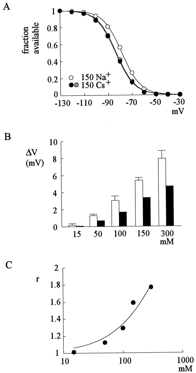
Shift of the inactivation curve by external Na+. A, The cell was held at −130 mV and stepped every 2 sec to the inactivating pulse (−130 to −30 mV) for 100 msec. The channels that remain available after each inactivating pulse were assessed by the peak currents during the following short test pulse to +40 mV for 20 msec. The fraction available is defined as the normalized peak current (relative to the peak current evoked with an inactivating pulse at −130 mV) and is plotted against the voltage of the inactivating pulse. Two sets of experiments were performed in 0 mm external Na+, before and after one set of experiments in 150 mm external Na+ to demonstrate negligible voltage drift during these experiments. Thelines are fits to each set of data of a Boltzmann function: fraction available = 1/(1 + exp((V− Vh)/k)), with Vh values (in mV) of −83.0, −78.3, and −83.5, and k values of 7.8, 7.7, and 7.8 for 0 mm Na+ (before 150 mm Na+), 150 mmNa+, and 0 mm Na+(after 150 mm Na+), respectively.B, Shift of the inactivation curve (ΔV) is determined in each cell by the difference between Vh in 0 mm and in various concentrations of external Na+. The white bars are the ΔV values before correction for the junctional potential differences and are 0.17 ± 0.20, 1.26 ± 0.16, 3.07 ± 0.46, 5.40 ± 0.30, and 7.93 ± 0.88 mV (n = 4–7) for 15, 50, 100, 150, and 300 mm external Na+, respectively. The mean values of ΔV are then corrected for the junctional potential difference of each solution (see Materials and Methods) to give the final values of ΔV, which are 0.07, 0.66, 1.77, 3.40, and 4.63 mV for 15, 50, 100, 150, and 300 mmexternal Na+, respectively (black bars). C, The r values are calculated using Equation 6 (see Results) as well as the ΔV (after corrections for the junctional potential differences) and k values in different concentrations of external Na+ from each cell in B. The averager value is then plotted against the concentration of external Na+. The line is a fit to the data points using Equation 9 (see Results), with aKd value of 620 mm and aq value of 3.5.
RESULTS
External Na+ has no effect on the initial delay but speeds the following exponential phase of the recovery time course
Figure 1 shows the double-pulse protocol and outward currents for the assessment of recovery from inactivation in Na+ channels. Similar to previous observations with inward Na+current (Kuo and Bean, 1994), the recovery time course begins with a delay, which is very similar in length whether the external solution contains 150 mm Na+ or 150 mm Cs+ (0 mmNa+). The subsequent phase of recovery, however, is apparently faster in 150 mm than in 0 mm Na+. These points are further illustrated in Figures 2 and3. Figure 2, A andB, plots typical time courses of recovery from inactivation in 150 and 0 mm external Na+. After the initial delay, the subsequent phase of recovery can be reasonably fitted by monoexponential functions. It is evident that the exponential phase is faster in 150 mm than in 0 mm external Na+, but the initial delay remains unchanged. Figure 3A shows cumulative results from different cells and again demonstrates that the initial delay is not changed by external Na+. In contrast, the time constant of the exponential phase in 0 mm external Na+ is ∼1.6 times as long as that in 150 mm external Na+(Fig. 3B,C). Furthermore, Figure3D shows that the ratios between the recovery time constants in 150 mm external Na+ and those in 0 mm external Na+ are very similar, with recovery potentials ranging from −100 to −180 mV. The facilitation effect of external Na+ on recovery from inactivation therefore seems to be voltage independent.
Fig. 1.

Recovery from inactivation of Na+ currents. The cell was held at −120 mV and pulsed twice to +20 mV (0 mm external Na+, top panel) or +60 mV (150 mm external Na+, bottom panel) for 10 msec. The pulse protocol was repeated every 2 sec, with a gradually lengthened gap between the two pulses at −100 mV (the “recovery potential”). The test pulse voltages (+20 or +60 mV) are chosen to make the peak currents roughly the same and thus facilitate a comparison between the initial delays. The first pulse serves to inactivate Na+ channels, and the second pulse serves to measure the fraction of Na+channels having recovered from inactivation. The sweeps are arranged so that the currents in the second pulse are gradually shifted rightward as the gap is lengthened (by 0.1 msec between each sweep). Thedashed lines mark the start of the recovery period, and the dotted lines mark the zero current level. Note there is an initial delay in the recovery courses, and the delay is very similar in length in either 0 or 150 mm external Na+. On the other hand, the recovery after the initial delay appears faster in 150 mmthan in 0 mm external Na+.
Fig. 2.

Measurement of the initial delay and the subsequent exponential phase of recovery from inactivation.A, With the double-pulse protocol in Figure 1, the average current in the last 2 msec in the first pulse is subtracted from the peak current in the second pulse. The fraction recovered is defined by normalizing each of the “corrected” peak currents in the second pulse to the one after the longest recovery period (∼100 msec), when the peak current in the second pulse always has reached an apparent plateau with an amplitude around 95% of the current in the first pulse. The fraction recovered is then plotted against the duration of the recovery potential to give the time course of recovery. The initial delay is barely discernible with this time scale. The recovery subsequent to the initial delay can be fitted by a monoexponential function of the form: fraction recovered = 1 − exp[−(x − id)/τ], wherex denotes the duration of recovery potential (the horizontal axis), and id denotes the length of the initial delay (which is defined in part B). The fitted time constants (τ) are 13.6 and 8.8 msec for 0 and 150 mmexternal Na+, respectively. These time constants remain the same with different test pulse voltages yet would be shortened with more hyperpolarizing recovery potentials [data not shown; see also Kuo and Bean (1994)]. B, The time courses of recovery in A are replotted with a different time scale for better resolution of the initial delay. Thedashed lines are linear regression fits to the data points between fraction recovered at 0.05 and 0.15. The intercepts of these regression lines on the horizontal axis are defined as the length of initial delay, which are 0.68 and 0.67 msec for 0 and 150 mm external Na+, respectively.
Fig. 3.

Cumulative results of the length of initial delay and the time constant of subsequent exponential phase of recovery.A, The experiments described in Figure 2 were repeated in four cells. The initial delays are 0.53 ± 0.05 and 0.54 ± 0.05 msec in length for 0 and 150 mm external Na+, respectively. B, In these four cells, the time constants of the exponential phase of recovery are 11.7 ± 1.8 and 7.3 ± 1.7 msec for 0 and 150 mmexternal Na+, respectively. C, The ratio between the length of initial delay in 0 mm and that in 150 mm external Na+ and the ratio between the time constant of the exponential phase in 0 mmand that in 150 mm external Na+ are calculated separately for each of the four cells. The ratios are 0.99 ± 0.03 and 1.60 ± 0.06 (n = 4) for the length of initial delay and the time constants of exponential recovery phase, respectively. D, The experiments were repeated at different recovery potentials (−100 to −180 mV). The ratios between the time constants of the exponential phase in 0 mm external Na+ and that in 150 mm external Na+ are calculated in the same way as that in C and are 1.60 ± 0.06, 1.62 ± 0.13, 1.45 ± 0.09, 1.54 ± 0.06, and 1.47 ± 0.04 (n = 3–4) for recovery potentials of −100, −120, −140, −160, and −180 mV, respectively.
External Na+ has no effect on the activation/deactivation kinetics of Na+ channels

Scheme 1 depicts a simplified channel gating model incorporating the aforementioned pore-blocking concept of inactivation. OB and CB denote the open (activated) and closed (deactivated) conformations blocked by the inactivating peptide, respectively. In principle, route C to O to OB is the major pathway for the development of inactivation, so that inactivation is coupled to activation and most channels in the closed state would remain unblocked and ready to be activated (steady-state occupancy of state C ≫ state CB). On the other hand, recovery of the inactivated channel (the channel in state OB) potentially may take either the OB to O to C (unblocking before deactivation) route or the OB to CB to C (deactivation before unblocking) route. The two routes have very different physiological meanings. The former implies substantial ionic currents through the channel traversing state O during recovery, whereas the latter assures no such current on repolarization.
In Na+ channels, the OB to CB to C route is preferred exclusively (Kuo and Bean, 1994). Thus at the beginning of recovery there is an initial delay, which corresponds to the time for the inactivated channel to move from state OB to CB. After the delay there is an exponential phase that corresponds to the CB to C transition (Kuo and Bean, 1994). The finding that the exponential phase at different recovery potentials is accelerated to the same extent (Fig. 3D) therefore suggests a voltage-independent facilitation effect of external Na+ on the CB to C step (unblocking of inactivating peptide from the deactivated channel), which is probably a voltage-independent process itself (Kuo and Bean, 1994). On the other hand, the unchanged initial delay in Figures 1-3 indicates that external Na+does not have an effect on the OB to CB step (deactivation of the inactivated Na+ channels).
If there is no effect of external Na+ on deactivation of the inactivated Na+channel, then it would be interesting to see whether external Na+ also has no effect on the deactivation of the activated Na+ channels (the O to C step in Scheme 1) or other “intrinsic” gating processes of the channel. Figure 4Ashows the currents recorded in different concentrations of external Na+, with or without 3 μm external tetrodotoxin (TTX). TTX (3 μm) blocks essentially all Na+ currents in hippocampal neurons (Kuo and Bean, 1994) and thus makes ideal “leak template” currents. Subtraction of such template currents eliminates most of the capacity transients and facilitates comparison of the early activation phases of Na+ currents in different conditions. When the peak currents are scaled to the same size, it is evident that the rising phase, and even the decaying phase, of the TTX-sensitive currents in different external Na+concentrations is almost identical (Fig. 4B). The very similar rising (activation) time of Na+ currents in different concentrations of external Na+ further strengthens the point that external Na+ has no effect on Na+ channel activation (Fig.4C).
Fig. 4.

Activation kinetics of Na+currents. A, The cell was held at −120 mV and pulsed to +40 mV for 20 msec to elicit Na+ current in either 0 mm (top panel) or 150 mmexternal Na+ (bottom panel). In either external solution, the pulse was delivered in the absence and then in the presence of 3 μm external tetrodotoxin (TTX). B, The TTX-sensitive currents in 0 and 150 mm Na+ are plotted in the top panel. For better illustration of the activation phase of the currents, only the first ∼3 msec of the currents are shown. In the bottom panel, the currents are scaled to the same peak amplitude to show the superimposed rising phases of the currents. C, The rising time of the Na+ currents in B is defined as the time interval between the initial deflection and the peak of the current. In six cells, the rising times are 0.143 ± 0.014 and 0.147 ± 0.010 msec in 0 and 150 mm external Na+, respectively.
Figure 5A shows the TTX-sensitive deactivating tail currents in 15 or 150 mm external Na+ at two different voltages. When the peak tail currents are scaled to the same size, the decaying kinetics of these tail currents are again almost identical in different concentrations of external Na+. It should be noted that according to Scheme 1, channels in state O would become nonconducting by proceeding to either state C (deactivation) or state OB (development of inactivation). The macroscopic decaying rate of the tail current therefore should be close to the summation of the O to C and O to OB rates (the C to O and OB to O rates are much smaller and are ignored for simplicity). Because the O to OB rate (∼350 sec−1) (Fig. 6) is not affected by external Na+ concentration and is much smaller than the decaying rates of the tail currents in Figure 5 (∼1000 and ∼630 sec−1, the inverses of decaying time constants 0.1 and 0.16 msec at −60 and −50 mV, respectively), the same decaying kinetics of the tail current in Figure 5 should still indicate the same deactivation (O to C) rate in 0 and 150 mm external Na+. Figure 5B further demonstrates similar voltage dependence of deactivation kinetics in different concentrations of external Na+. We therefore conclude that external Na+has no effect on the deactivation processes of Na+ channels, whether the channel is blocked by the inactivating peptide or not.
Fig. 5.
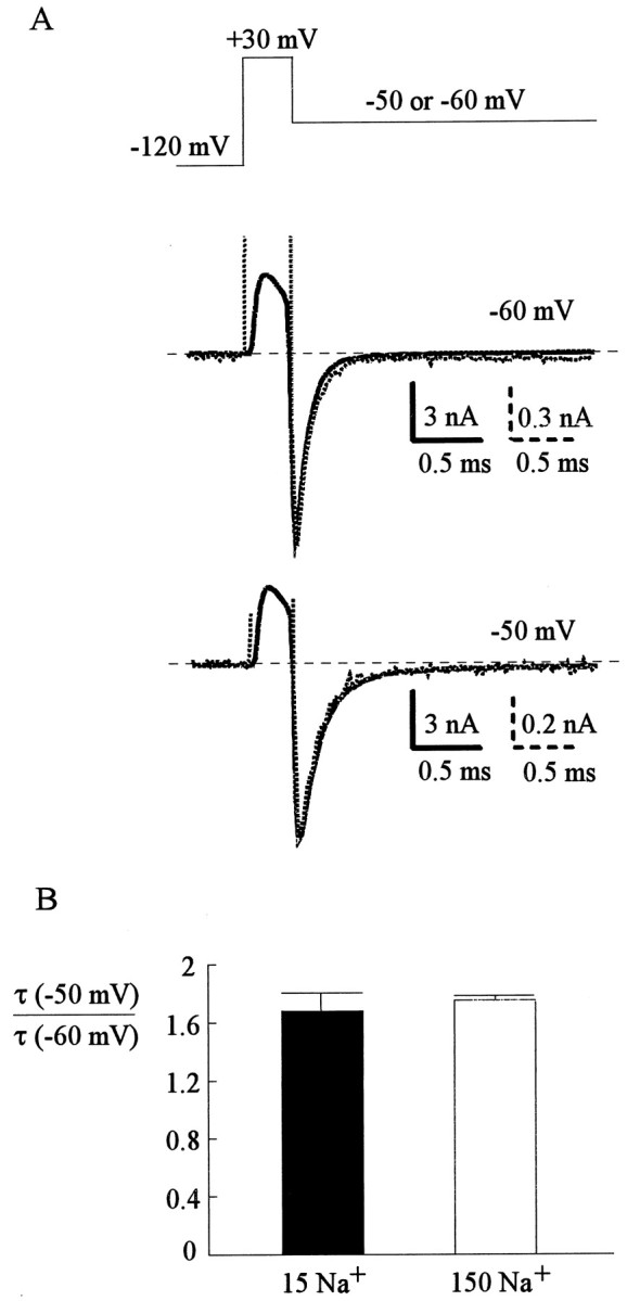
Deactivating kinetics of Na+currents. A, The cell was held at −120 mV and was given a short depolarizing pulse at +30 mV for 0.3 msec before being repolarized to −60 or −50 mV to document the inward tail currents. The depolarizing test pulse was kept very short to avoid significant inactivation of the channel. Repolarization to −70 mV or more negative potentials was not feasible because tail currents at such negative potentials were too large (especially in 150 mm external Na+) or deactivated too fast to be reliably recorded and analyzed. At each repolarization potential (−60 and −50 mV), the tail currents in 15 mm (dotted lines) or 150 mm external Na+ (solid lines) are scaled to the same size. The decaying time constants obtained from monoexponential fits to these deactivating currents are 0.11 msec (−60 mV, 150 mm Na+), 0.11 msec (−60 mV, 15 mm Na+), 0.18 msec (−50 mV, 150 mm Na+), and 0.17 msec (−50 mV, 15 mm Na+). B, In each individual cell the ratio between the time constant at −50 mV and that at −60 mV is calculated. The ratios are 1.68 ± 0.13 and 1.75 ± 0.03 (both n = 4) in 15 and 150 mm external Na+, respectively. The similar ratios suggest that external Na+ does not have a significant effect on the voltage dependence of Na+ channel deactivation.
Fig. 6.

Inactivation kinetics of Na+current. The cell was held at −120 mV, and pulsed to +20 to +140 mV for 10 msec to elicit Na+ currents in either 0 or 150 mm external Na+. The time constant obtained from monoexponential fit to the decaying phase of Na+ currents in five cells is plotted against the pulse potential. The time constants are very similar in different concentrations of external Na+ at every potential.
The effects of external Na+ on the unblocking processes are quantitatively the same whether the Na+ channel has deactivated or not
Because the exponential recovery phase after the initial delay represents the unblocking CB to C step (Kuo and Bean, 1994), acceleration of this phase by external Na+ indicates that external Na+ facilitates unbinding of the inactivating peptide (hinged lid) from its binding site in the deactivated channel pore. It is thus desirable to see whether external Na+ also has an effect on the blocking and unblocking step of the inactivating peptide in the activated channel pore (O to OB and OB to O steps in Scheme 1). Figure 6 shows that the time constants of the decaying phase of macroscopic Na+ current are very similar in different concentrations of external Na+. In either 0 or 150 mm external Na+, the time constants get shorter with increasing depolarization up to +100 mV and then approach a saturating value of ∼0.28 msec at more positive potentials. In theory, this would mean a sum of O to OB and OB to O rates of ∼350 sec−1. Because at these positive potentials most Na+ channels are inactivated at steady state, the O to OB rate should be much larger than OB to O rate. The foregoing saturating time constant of ∼0.28 msec thus suggests a voltage-independent O to OB rate of ∼350 sec−1.
With an unchanged O to OB rate in different concentrations of external Na+, one may assess the OB to O rate by the steady-state Na+ current late in a depolarizing pulse. According to Scheme 1, this late current should be determined by the ratio between the OB to O rate and the O to OB rate. Here the TTX-sensitive currents are used again to eliminate contamination from leak or any small currents of the other kind. Because of the difference in driving force with different external Na+ concentrations, it would be inappropriate to compare the absolute level of the steady-state currents in different experimental conditions. In view of the unchanged activation and inactivation rates in different external Na+ concentrations (Figs. 4, 6), the peak current of each sweep may make an ideal normalization standard for eliminating the effect of different driving forces. Figure7, A–C, shows that the normalized late, steady-state current in the presence of 150 mm external Na+ is ∼1.7 times as large as that in zero external Na+. This number remains the same if different test pulses are used (e.g., +60 mV; data not shown). AlthoughTownsend et al. (1997) reported an external Na+-related, highly voltage-dependent peak open probability change in mutant heart Na+ channels with significantly impaired fast inactivation, such a change seems negligible in Na+ channels that have intact fast inactivation or are blocked by internal blockers (Townsend et al., 1997; Townsend and Horn, 1999). The intact fast inactivation in native neuronal Na+ channels and the voltage independence of our findings thus may justify the use of peak currents for normalization. We conclude that unblocking of the bound inactivating peptide from either the activated channel (OB to O step) or the deactivated channel (CB to C step) is probably accelerated to the same extent by external Na+, and the effect appears voltage independent in either case.
Fig. 7.
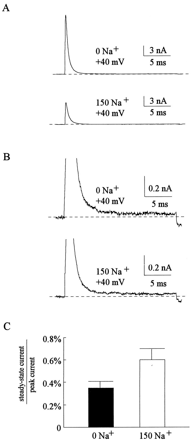
Steady-state Na+ current in depolarizing pulses. A, TTX-sensitive currents were obtained in either 0 mm (top panel) or 150 mm external Na+ (bottom panel) with the same protocol as that in Figure 4.B, The currents in A are redrawn with a different scale for a better resolution of the small sustained currents late in the pulse. C, The average currents in the last 2 msec of each depolarizing pulse (steady-state current) are calculated and then divided by the peak currents of the same pulse. The ratios between the steady-state and the peak currents are 0.35 ± 0.06 and 0.6 ± 0.01% (n = 5) in 0 and 150 mm external Na+, respectively.
The affinity between external Na+ and the facilitation site can be determined by shift of the inactivation curve
We have seen that external Na+ does not change the activation/deactivation gating processes of the channel. Also, external Na+ has no effect on the O to OB step but accelerates the OB to O step. External Na+ thus should change the steady-state distribution of the channel between states O and OB but not the distribution between states C and O. Consequently the steady-state distribution of the channel between states C and OB will be changed by external Na+. Because of the much smaller steady-state occupancy of state O than state OB (O to OB rate ≫ OB to O rate), and the much smaller occupancy of state CB than state C (C to CB rate ≪ CB to C rate), the inactivation curve of Na+ channels (Fig.8A) essentially describes the steady-state distribution of the channel between states C and OB. This curve therefore would be different in different concentrations of external Na+. These points may be elaborated in a more quantitative way. Based on Scheme 1, the fraction of available channels at the steady state (F) may be expressed as:
| Equation 1 |
Where C, O, OB, and CB denote the steady-state occupancy (fractional distribution) of the channel in each different gating state. If CB : C : O : OB equals m : 1 : x :nx at a particular voltage in the absence of external Na+, then we have m ≪ 1 ≪n because CB ≪ C and O ≪ OB, and F can be approximated by:
| Equation 2 |
and therefore,
| Equation 3 |
If in a certain concentration of external Na+ the CB to C rate and the OB to O rate are both accelerated and become r-fold of the rate in 0 mm external Na+(whereas the other gating processes are unchanged, e.g., C : O still equals 1 : x), then CB : C : O : OB becomes m :r : rx : nx and the fraction of available channel becomes F':
| Equation 4 |
Based on the findings in Figures 3 and 7, r is only ∼1.7 in 150 mmNa+. If m ≪ r ≪n holds true, then we have:
| Equation 5 |
Let
| Equation 6 |
| Equation 7 |
By comparing Equations 2 and 7, one can see that F' should have the same shape (slope factor k) as Fbut will be shifted in the horizontal axis by ΔV, which is equal to k * ln r (Eq. 6). This is exactly the case in Figure 8A, where the inactivation curves remain very similar in shape but are shifted in the voltage axis in the presence of 150 mm external Na+. The amount of shift (ΔV) increases with increased external Na+ concentration, and there are no signs of saturation in up to 300 mm external Na+ [(Fig. 8B) whether the junctional potentials are corrected or not], which may imply a very low affinity of Na+ to the binding site facilitating the unblocking process of the inactivating peptide. Assuming one-to-one binding of external Na+ to the facilitation site, we have:
| Equation 8 |
where OP is the occupancy of the facilitation site by external Na+, Kdis the dissociation constant of external Na+ binding to this site, and Na is external Na+ concentration. If the unbinding rate of the inactivating peptide with a Na+ ion in the facilitation site isq times of the unbinding rate when the site is empty, thenr in Equations 4-6 may be expressed as:
| Equation 9 |
Figure 8C shows the r values derived from the ΔV (after correction for the junctional potentials) and k data in each cell in Figure 8B using Equation 6. The r value in 150 mmexternal Na+ obtained with this approach is ∼1.6, which is very much consistent with those obtained with completely different approaches in Figures 3 and 7. The quantitative consistency of these results strongly supports the foregoing proposal that external Na+ has a facilitation effect on the unbinding of the inactivating peptide yet does not change the other gating kinetics of the Na+channel. The best fitting curve using Equation 9 reveals aKd value of 620 mm and a q value of 3.5. Because we do not have data in a higher concentration range of external Na+ to see the saturation of r(it is difficult to maintain the seal long enough and get reliable data with molar concentrations of external Na+), theseKd and q values may not be very accurate estimates. However, it seems evident that the affinity between external Na+ and the facilitation site is very low.
DISCUSSION
A small but definite effect of external Na+ on the unbinding of the inactivating peptide
We have demonstrated that the activation/deactivation kinetics of macroscopic Na+ currents and the initial delay of recovery from inactivation are all unchanged by external Na+. On the other hand, the exponential phase of recovery from inactivation, the late (steady-state) current during a test pulse, and the shift of the inactivation curve all indicate a ∼1.6-fold faster unbinding rate of the bound inactivating peptide in 150 mm than in 0 mm external Na+, no matter whether the unbinding is from the activated or deactivated channels. The facilitation of the unbinding step cannot be ascribed to the 2 mV junctional potential difference between 0 and 150 mmNa+ solutions, because it would take a further hyperpolarization of >10 mV to accelerate the exponential recovery phase by 1.6 times at a recovery potential of −100 mV [and even larger hyperpolarization to make the 1.6 time acceleration at more negative recovery potentials (Kuo and Bean, 1994)]. Moreover, at a recovery potential of -180 mV the exponential phase of recovery is “saturated” and no longer accelerated by further hyperpolarization (Kuo and Bean, 1994), but the facilitation effect of external Na+ remains the same (Fig. 3D). Along with the foregoing arguments, we conclude that there is a true and definite facilitation effect of external Na+ on the unbinding of the inactivating peptide.
Coupling between inactivation and activation/deactivation and possible mechanisms underlying the facilitation effect of external Na+
In Na+ channels the development of inactivation is coupled to activation (Bezanilla and Armstrong, 1977;Armstrong, 1981), and recovery from inactivation is coupled to deactivation (Kuo and Bean, 1994). The molecular basis of such couplings may involve several conformational changes of the channel protein during activation (and reverse changes during channel deactivation), including a “pull” at the inactivating peptide (to cover the activated channel pore) and the formation of a receptor to bind the pulled lid (and thus stabilization of the inactivated conformation). In view of the couplings between inactivation and other gating processes, facilitation of the unbinding step by external Na+ conceivably may have two different mechanisms. First, the Na+ ion may bind to a site that is just beside the receptor for the lid, and thus directly knocks off the pore-blocking inactivating peptide (the bound inactivation gate). Second, external Na+ion may bind to a site distant from the bound inactivation gate yet facilitate opening of this gate via allosteric effects. The allosteric effect of external ligands on fast inactivation could be exemplified by the action of batrachotoxin and anthopleurin-A (a site-3 toxin) (Hanck and Sheets, 1995), both of which prevent fast inactivation of the Na+ channel when applied externally. This is conceivable in view of the outward movements of the voltage sensor S4 segments at depolarization (Yang and Horn, 1995; Yang et al., 1996;Mitrovic et al., 1998). If the toxins interfere with the movement of an S4 that is especially associated with channel inactivation (Kuhn and Greeff, 1999; Sheets et al., 1999), fast inactivation may be prevented.
Direct knock-off of the bound inactivating peptide by external Na+
We have seen that the facilitation effect is quantitatively the same whether the channel is activated or deactivated. With the direct knock-off model, it is conceivable that the presence of a Na+ ion next to the inactivating peptide elevates the free energy of the bound peptide by a fixed quantity and thus always accelerates unbinding of the peptide to the same extent regardless of the different (gating) conformations of the channel. Under such circumstances the voltage independence of the facilitation effect may be explained by the fact that the pore is blocked (by the inactivating peptide) while external Na+is exerting the effect. If most of the electric field falls across the blockade, the facilitation effect would show little voltage dependence. On the other hand, with the allosteric model it is far less straightforward why the facilitation effect should remain the same in different gating states and different membrane voltages. The allosteric effect presumably is initiated from an external site by Na+ binding and is finally transmitted to the internally located receptor, hinge, or lid to facilitate unbinding of the inactivating peptide. Because the activation/deactivation processes are not changed by external Na+, and because there is always the same facilitation regardless of gating status and membrane voltage, transmission of this allosteric facilitation effect should stay clear of all other major conformation-changing (gating) processes in the channel protein. Also, as we have mentioned, local conformations of the receptor, hinge, or lid may be critically different between deactivated and activated channels (thus CB to C rate ≫ OB to O rate) (Kuo and Bean, 1994). The same facilitation in different gating states thus requires the same allosteric effect with different “basal” conformations of the target protein regions. These are not absolutely impossible conditions, but chances of such structural and quantitative coincidences seem low.
Tang et al. (1996) showed that cytoplasmic application of pentapeptide KIFMK increases the current decaying rate of a mutant Na+ channel, in which both development of inactivation and recovery from inactivation are slowed by point mutations in the S4–S5 linker in the fourth domain of the channel. External Na+ has no effect on the “residual” inactivation in this mutant but antagonizes the effect of KIFMK. It has been shown that amino acids IFM in the inactivating peptide constitute the key structure interacting with the receptor (West et al., 1992; Eaholtz et al., 1994). Because KIFMK effectively blocks the channel pore (or restores the blocking effect of the inactivating peptide) (Kuroda et al., 1999), the receptor for the IFM-containing particle presumably is still formed during activation of the mutant channel. This would indicate some intact allosteric mechanisms underlying fast inactivation in the mutant. The lack of effect of external Na+ on the residual inactivation therefore may imply that external Na+ does not affect the (residual) allosteric mechanisms underlying inactivation. Moreover, external Na+ seems to antagonize blockade by the IFM-containing peptide only when binding of the peptide happens in a certain way, because an “impaired” or somewhat different binding caused by the aforementioned S4–S5 linker mutations would make the blockade no longer sensitive to external Na+. This could suggest a very local or direct knock-off effect of external Na+ on the IFM-containing inactivating peptide.
It has been shown that external K+facilitates recovery from fast inactivation in A-type K+ channels (Demo and Yellen, 1991;Gomez-Lagunas and Armstrong, 1994; Kuo, 1997). Moreover, attachment of the D3–D4 linker of the Na+ channel to the N-terminal of a noninactivating K+channel results in rapid inactivation of the chimeric channel, and the inactivation is also antagonized by external K+ (Patton et al., 1993). Because the molecular mechanisms underlying the allosteric coupling between activation/deactivation and inactivation may be somewhat different among A-type K+ channels (composed of four separate subunits, the ball-and-chain model of inactivation), noninactivating K+ channels (“artificially inactivated” by an exogenous inactivating peptide), and Na+ channels (composed of four connected domains, the hinged-lid model of inactivation), similar facilitation of the unbinding of the inactivating peptide by external permeating ions in all these channels would also sustain that permeating ions directly knock off the bound inactivation gate.
Location of the activation gate in Na+ channels
From removal of fast inactivation by internal pronase (Armstrong et al., 1973) to restoration of fast inactivation by internally applied inactivation peptide KIFMK (Eaholtz et al., 1994), there has been much evidence suggesting that the fast inactivation gate of Na+ channels is located close to the internal end of the pore. On the other hand, although the structural correlates of many conformational changes associated with channel activation have been documented, the location of the activation gate, or the key conforma-tional change that transforms a Na+-nonconducting pore into a Na+-conducting one during channel activation, remains an open question. If permeating Na+ ions directly knock off the bound inactivating peptide, then the same effect of external Na+ regardless of the gating status of the channel would strongly suggest that the accessibility of the enhancement site to external Na+ is unchanged by channel activation/deactivation, which would in turn suggest that the activation gate in the Na+ channel pore is not located external to the bound inactivation gate and thus is probably also located close to the cytoplasmic end of the pore. This location of the activation gate would be consistent with the proposal of Townsend and Horn (1999), namely a largely preserved permeation pathway in a closed Na+ channel. If the activation gate is in the same area as (i.e., partially overlaps with) the receptor site for the inactivating peptide, then modulation of the receptor for the inactivating peptide could be caused by the opening of the activation gate itself, rather than an allosteric process happening with or induced by activation gate opening. If the activation gate is located even more internally (than the receptor), then the receptor could be “guarded” rather than “modulated” by the activation gate and is much more accessible to the inactivating peptide when the activation gate is open. In this regard it is interesting to note that channel deactivation facilitates unbinding of the bound inactivating peptide in Na+ channels (Kuo and Bean, 1994) but has an opposite effect and retards unbinding of the peptide in Shaker K+ channels (Kuo, 1997). Probably in Na+ channels there is an inactivating peptide receptor that is modulated by an activation gate located roughly in the same region, whereas in Shaker K+ channels the receptor is guarded by a more internally located activation gate (Kuo, 1997).
Footnotes
This work was supported by Grant NSC-89-2320-B-002-068 from the National Science Council, Taiwan, Republic of China.
Correspondence should be addressed to Chung-Chin Kuo, Department of Physiology, National Taiwan University College of Medicine, No. 1, Jen-Ai Road, 1st Section, Taipei, 100, Taiwan, Republic of China. E-mail: cckuo@ha.mc.ntu.edu.tw.
REFERENCES
- 1.Armstrong CM. Sodium channels and gating currents. Physiol Rev. 1981;61:644–683. doi: 10.1152/physrev.1981.61.3.644. [DOI] [PubMed] [Google Scholar]
- 2.Armstrong CM, Bezanilla F. Inactivation of the sodium channel. II. Gating current experiments. J Gen Physiol. 1977;70:567–590. doi: 10.1085/jgp.70.5.567. [DOI] [PMC free article] [PubMed] [Google Scholar]
- 3.Armstrong CM, Bezanilla F, Rojas E. Destruction of sodium conductance inactivation in squid axons perfused with pronase. J Gen Physiol. 1973;62:375–391. doi: 10.1085/jgp.62.4.375. [DOI] [PMC free article] [PubMed] [Google Scholar]
- 4.Bezanilla F, Armstrong CM. Inactivation of the Na+ channel. I. Sodium current experiments. J Gen Physiol. 1977;70:549–566. doi: 10.1085/jgp.70.5.549. [DOI] [PMC free article] [PubMed] [Google Scholar]
- 5.Demo SD, Yellen G. The inactivation gate of the Shaker potassium channel behaves like an open-channel blocker. Neuron. 1991;7:743–753. doi: 10.1016/0896-6273(91)90277-7. [DOI] [PubMed] [Google Scholar]
- 6.Eaholtz G, Scheuer T, Catterall WA. Restoration of inactivation and block of open sodium channels by an inactivation gate peptide. Neuron. 1994;12:1041–1048. doi: 10.1016/0896-6273(94)90312-3. [DOI] [PubMed] [Google Scholar]
- 7.Gomez-Lagunas F, Armstrong CM. The relation between ion permeation and recovery from inactivation of ShakerB K+ channels. Biophys J. 1994;67:1806–1815. doi: 10.1016/S0006-3495(94)80662-9. [DOI] [PMC free article] [PubMed] [Google Scholar]
- 8.Hanck DA, Sheets MF. Modification of inactivation in cardiac sodium channels: ionic current studies with anthopleurin-A toxin. J Gen Physiol. 1995;106:601–616. doi: 10.1085/jgp.106.4.601. [DOI] [PMC free article] [PubMed] [Google Scholar]
- 9.Hoshi T, Zagotta WN, Aldrich RW. Biophysical and molecular mechanisms of Shaker potassium channel inactivation. Science. 1990;250:533–538. doi: 10.1126/science.2122519. [DOI] [PubMed] [Google Scholar]
- 10.Kuhn FJP, Greeff NG. Movement of voltage sensor S4 in domain 4 is tightly coupled to sodium channel fast inactivation and gating charge immobilization. J Gen Physiol. 1999;114:167–183. doi: 10.1085/jgp.114.2.167. [DOI] [PMC free article] [PubMed] [Google Scholar]
- 11.Kuo C-C. Deactivation retards recovery from inactivation in Shaker K+ channels. J Neurosci. 1997;17:3436–3444. doi: 10.1523/JNEUROSCI.17-10-03436.1997. [DOI] [PMC free article] [PubMed] [Google Scholar]
- 12.Kuo C-C, Bean BP. Na+ channels must deactivate to recover from inactivation. Neuron. 1994;12:819–829. doi: 10.1016/0896-6273(94)90335-2. [DOI] [PubMed] [Google Scholar]
- 13.Kuroda Y, Maeda Y, Miyamoto K, Tanaka K, Kanaori K, Otaka A, Fugii N, Nakagawa T. 1H-NMR and circular dichroism spectroscopic studies on changes in secondary structures of the sodium channel inactivation gate peptides as caused by the pentapeptide KIFMK. Biophys J. 1999;77:1363–1373. doi: 10.1016/S0006-3495(99)76985-7. [DOI] [PMC free article] [PubMed] [Google Scholar]
- 14.Mitrovic N, George AL, Jr, Horn R. Independent versus coupled inactivation in sodium channels: role of the domain 2 S4 segment. J Gen Physiol. 1998;111:451–462. doi: 10.1085/jgp.111.3.451. [DOI] [PMC free article] [PubMed] [Google Scholar]
- 15.O'Leary ME, Kallen RG, Horn R. Evidence for a direct interaction between internal tetraalkylammonium cations and the inactivation gate of cardiac sodium channels. J Gen Physiol. 1994;104:523–539. doi: 10.1085/jgp.104.3.523. [DOI] [PMC free article] [PubMed] [Google Scholar]
- 16.Patton DE, West JW, Catterall WA, Goldin AL. A peptide segment critical for sodium channel inactivation functions as an inactivation gate in a potassium channel. Neuron. 1993;11:967–974. doi: 10.1016/0896-6273(93)90125-b. [DOI] [PubMed] [Google Scholar]
- 17.Shapiro BI. Effects of strychnine on the sodium conductance of the frog node of Ranvier. J Gen Physiol. 1977;69:915–926. doi: 10.1085/jgp.69.6.915. [DOI] [PMC free article] [PubMed] [Google Scholar]
- 18.Sheets MF, Kyle JW, Kallen RG, Hanck DA. The Na channel voltage sensor associated with inactivation is localized to the external charged residues of domain IV, S4. Biophys J. 1999;77:747–757. doi: 10.1016/S0006-3495(99)76929-8. [DOI] [PMC free article] [PubMed] [Google Scholar]
- 19.Tang L, Kallen RG, Horn R. Role of an S4–S5 linker in sodium channel inactivation probed by mutagenesis and a peptide blocker. J Gen Physiol. 1996;108:89–104. doi: 10.1085/jgp.108.2.89. [DOI] [PMC free article] [PubMed] [Google Scholar]
- 20.Townsend C, Horn R. Interaction between the pore and a fast gate of the cardiac sodium channel. J Gen Physiol. 1999;113:321–331. doi: 10.1085/jgp.113.2.321. [DOI] [PMC free article] [PubMed] [Google Scholar]
- 21.Townsend C, Hartmann HA, Horn R. Anomalous effect of permeant ion concentration on peak open probability of cardiac sodium channels. J Gen Physiol. 1997;110:11–21. doi: 10.1085/jgp.110.1.11. [DOI] [PMC free article] [PubMed] [Google Scholar]
- 22.West JW, Patton DE, Scheuer T, Wang Y, Goldin AL, Catterall WA. A cluster of hydrophobic amino acid residues required for fast Na+ channel inactivation. Proc Natl Acad Sci USA. 1992;89:10910–10914. doi: 10.1073/pnas.89.22.10910. [DOI] [PMC free article] [PubMed] [Google Scholar]
- 23.Yang NB, Horn R. Evidence for voltage-dependent S4 movement in sodium channels. Neuron. 1995;15:213–218. doi: 10.1016/0896-6273(95)90078-0. [DOI] [PubMed] [Google Scholar]
- 24.Yang NB, George AL, Jr, Horn R. Molecular basis of charge movement in voltage-gated sodium channels. Neuron. 1996;16:113–122. doi: 10.1016/s0896-6273(00)80028-8. [DOI] [PubMed] [Google Scholar]
- 25.Zagotta WN, Hoshi T, Aldrich RW. Restoration of inactivation in mutant Shaker potassium channels by a peptide derived from ShB. Science. 1990;250:568–571. doi: 10.1126/science.2122520. [DOI] [PubMed] [Google Scholar]