Abstract
Polarization is an intrinsic attribute of optical waves, so manipulating the polarization state of optical surface waves can be of a fundamental importance for the next-generation information and bio-photonics technology. Here, we show theoretically that the polarization of the Bloch surface wave (BSW) on a dielectric multilayer can be transformed between a transverse-electric (TE) state and a transverse-magnetic (TM) state by using the laterally continuous grooves inscribed on this multilayer. This polarization transformation can be enhanced or inhibited by the interference between the reflected BSW beams, which can be tuned by the periodicity and depth of the grooves. The maximum polarization transformation efficiency can be achieved as high as 43% when the number of grooves is increased to 10. A generalized Fresnel formula is proposed to describe the polarization transformation of the BSW beams. Due to this polarization transformation, an anomalous reflection of BSW beams can be realized, which is the inequality between the incident angle and the reflection angle.
I. INTRODUCTION
Bloch surface waves (BSWs), the electromagnetic surface waves excited at the interface between a truncated periodic dielectric multilayer with a photonic band gap (PBG) and its surrounding medium, have been considered as the dielectric analogue of surface plasmon polaritons (SPPs) that are also the electromagnetic surface waves but propagating at the interface between a metallic film and its dielectric cladding [1–2]. Similar as the SPPs, BSWs can also induce the optical near-field confinement and enhancement, and can have larger wave-vectors than light of the same frequency in vacuum. BSWs have been applied in nanoscale optical waveguides, sensing, fluorescence emission enhancement or sorting, surface enhanced Raman scattering, and so on [3–13]. It also can realize the giant Goos-Hanchen shift, which will improve the functionality of sensors and may have an impact on the further development of sensor technology [14]. The BSWs are not subject to losses caused by absorption in metal, which allows for BSW with a high resonance quality factor and a long propagation length. There are many choices of the dielectric materials for BSWs, which allows this dielectric multilayer to be used from deep ultraviolet (UV) to near-infrared (NIR) wavelengths [15]. For SPPs, it can only be sustained in transverse magnetic (TM) polarization state [16–19], whereas the BSWs can be of either transverse electric (TE) or TM polarization. Previously, most work on BSWs are related with the TE polarized BSW [3–11, 20], but few on the TM polarized one [12, 13]. The reason is that the generation of TM polarized BSWs is always affected by the Brewster angle effect [21]. There are no reports on energy coupling between the TE and TM polarized BSW, or reports on how to transform the TE polarized BSW into TM one and vice versa. Polarization is one of the basic parameters for optical waves, hence the ability to manipulate the polarization state of the electromagnetic surface waves can be of a fundamental importance for both science and technology. For example, it can increase the information capacity with a new parameter (polarization) involved in the surface waves, similar as the applications of cylindrical vector beams or orbital angular momentum in optical communications [22, 23]. It can also introduce different light-matter interactions between electromagnetic surface waves and polarization sensitive materials or cells. Although 3D waveguide based polarization rotators are routinely used in modern photoelectric components and provide nearly unitary efficiency of polarization transformation [24, 25], we have not seen any reports on the polarization rotators for 2D surface waves.
II. THE DISPERSION RELATIONS OF BSW
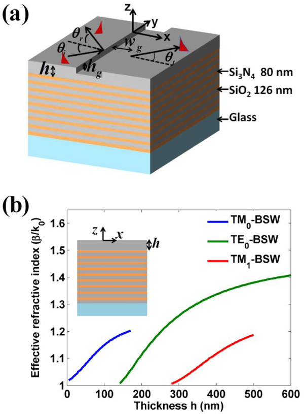
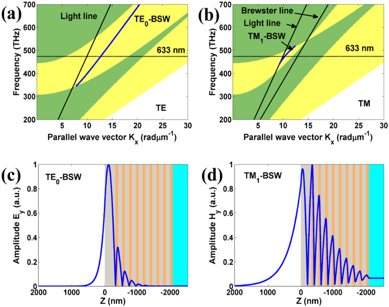
The proposed dielectric multilayer that sustains both TE and TM polarized BSWs is consisted of 18 alternating dielectric layers of Si3N4 and SiO2 as shown in Fig. 1(a). The refractive indices of Si3N4 and SiO2 layers are 2.65 and 1.48, respectively. The thickness of Si3N4 and SiO2 layers are fixed at 80 nm and 126 nm, respectively. The thickness of the top SiO2 layer can be varied and denoted as h. A rectangular groove with width wg and depth hg is inscribed on the top SiO2 layer. A BSW is obliquely incident on the groove. The symbols θi, θr and θt denote the incidence, reflection and transmission angles of BSW, respectively. Different from the SPPs supported by the metal film, the dielectric multilayer can support the propagation of TE-BSW (the electric field perpendicular to X-Z plane) and TM-BSW (the magnetic perpendicular to the X-Z plane). Moreover, the propagation of BSW is sensitive to the top layer’s thickness h as shown in the inset of Fig. 1(b). Figure 1(b) demonstrates the change of the effective refractive indices of TE-BSW and TM-BSW modes as a function of the top layer’s thickness h. The effective refractive indices of TE-BSW and TM-BSW modes decrease with the decreasing of the thickness h. Compared with the case of TE-BSW modes, the TM-BSW modes can be sustained by dielectric multilayer in a very limited thickness range, which is attributed to that the bandgap width of dielectric multilayer for TM polarization is much smaller than that for TE polarization due to the Brewster effect of TM polarization. The photonic bandgap of the dielectric multilayer and the dispersion relations for TE-BSW and TM-BSW modes are shown in Figs. 2(a) and 2(b), respectively. The yellow zone denotes the photonic stop band of dielectric multilayer. As the top layer’s thickness is fixed at 320 nm, the dispersion curves for TE0-BSW and TM1-BSW are also shown in Figs. 2(a) and 2(b), respectively. It is noted that the dispersion curve for TM1-BSW can be held in a very limited frequency range due to the narrow bandgap. To understand the waveguiding behaviors of BSW, the field distributions for TE0-BSW and TM1-BSW are shown in Figs. 2(c) and 2(d), respectively. A node of field for TM1-BSW can be observed in the top’s layer, but there is no node in the top’s layer for TE0-BSW. It is the reason that the mode is named according to the number of field node in the top’s layer of dielectric multilayer. In addition, the penetration depth of TM1-BSW in the dielectric multilayer is larger than that of TE0-BSW due to the narrow bandgap. As noted in Fig. 1(b), the dielectric multilayer can sustain the TE0-BSW and TM1-BSW modes with the thickness h ranging from 300 nm to 500 nm.
FIG. 1.
(a) Schematic illustration of the dielectric multilayer. The dielectric multilayer is consisted of 18 alternating dielectric layers of Si3N4 (80-nm-thick) and SiO2 (126-nm-thick). The thickness of top SiO2 layer can be varied and denoted as h. A groove with rectangle cross section is inscribed on the top SiO2 layer. The width and depth of groove are denoted as wg and hg, respectively. (b) the effective refractive indices of TE-BSW and TM-BSW modes versus the thickness h of top SiO2 layer.
FIG. 2.
The projected band structure of the dielectric multilayer for (a) TE polarization, (b) TM polarization. The yellow zone denotes the stop band. The blue solid lines denote the dispersion curves for BSW with the thickness h =320 nm. (c) The electric field distribution for TE0-BSW. (d) The magnetic field distribution for TM1-BSW. The field distributions are calculated at the wavelength 633 nm.
III. POLARIZATION TRANSFORMATION OF BSW
A. The case of the single groove
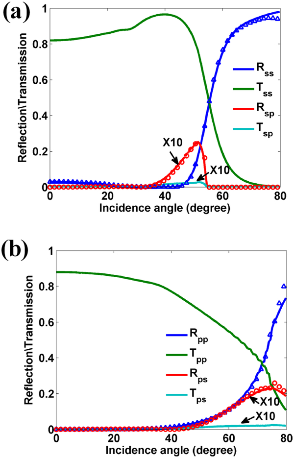
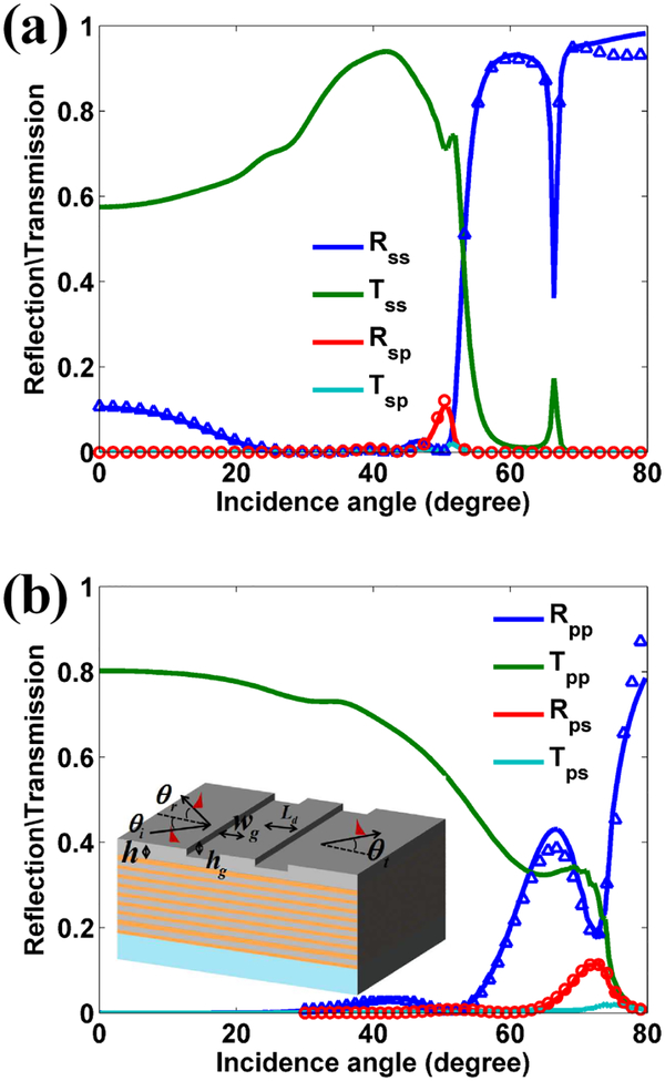
Here, a groove was fabricated on the dielectric multilayer as shown in Fig. 1(a). As the BSW is obliquely incident on the groove, the interpolarization coupling between TE-BSW and TM-BSW occurs due to the discontinuous of the interface, besides the partial reflection and transmission of BSW. The reflection, transmission and polarization transformation intensities of TE0-BSW and TM1-BSW as a function of the incidence angle are shown in Figs. 3(a) and 3(b), respectively. The results are obtained by mode-matching method [26, 27]. The validity of mode-matching method is confirmed by comparing with the results obtained from the finite difference frequency domain (FDFD) method [28]. The detailed descriptions of the simulation process are given in the Supplemental Material [29]. If the incident wave is TE0-BSW, Rss and Tss denote the reflection and transmission intensities of TE0-BSW, Rsp and Tsp denote the reflection and transmission intensities of TM1-BSW which are excited by the incident TE0-BSW. Similarly, if the incident wave is TM1-BSW, Rpp and Tpp denote the reflection and transmission intensities of TM1-BSW, Rps and Tps denote the reflection and transmission intensities of TE0-BSW excited by the TM1-BSW. To facilitate the comparison of the polarization transformation efficiency of BSW, the intensities of Rsp, Rps, Tsp and Tps are magnified by a factor of 10 in the curves shown in Figs. 3(a) and 3(b).
FIG. 3.
(a) The reflection (Rss), transmission (Tss) and polarization transformation (Rsp and Tsp) intensities of TE0-BSW versus the angle of incidence. (b) The reflection (Rpp), transmission (Tpp) and polarization transformation (Rps and Tps) intensities of TM1-BSW versus the angle of incidence. The signs with triangle and circle denote the results obtained from FDFD method. In simulation, the top layer’s thickness h = 320 nm, the width wg and depth hg of the groove are 400 nm and 150 nm, respectively. The intensities of Rsp, Tsp, Rps and Tps are magnified by a factor of 10. The incident wavelength of the light in vacuum is 633 nm.
As the BSW propagates across the groove, the reflection and transmission of BSW are well related to the difference of effective refractive indices of BSW inside and outside of the groove. Because the effective refractive index of TE0-BSW is larger than that of TM1-BSW for the same top layer’s thickness, the reflection and transmission curves of TE0-BSW demonstrate much more drastic changes at the large incidence angle. For example, as the incidence angle of TE0-BSW is larger than 50°, the reflection intensity of TE0-BSW is dramatically increased with the increasing of the incidence angle, and finally approaches one as shown in Fig. 3(a). The polarization transformation Rsp from TE0-BSW to TM1-BSW is firstly increased with the increasing of the incidence angle, but finally disappears around 55° due to the total internal reflection of TM1-BSW, which is determined by matching the transverse wavevector.
| (1) |
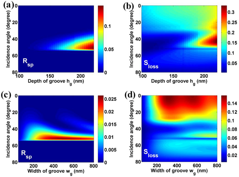
where and are the effective refractive indices of TE0-BSW and TM1-BSW, respectively. Because the effective refractive index of TM1-BSW is smaller than that of TE0-BSW, the total internal reflection angle of TM1-BSW is expressed as: . In contrast, as the incident BSW is TM1-BSW, the total internal reflection cannot occur, and the reflected angle of TE0-BSW excited by TM1-BSW can be expressed as: . There will be two reflected beams propagating along different directions due to the different effective refractive indices for TE0-BSW and TM1-BSW at the same top layer’s thickness, as the BSW is obliquely incident on the groove. Besides the incidence angle, the depth and width of groove can also affect the polarization transformation efficiency of BSW. The influences of the depth and width of groove to the polarization transformation efficiency of TE0-BSW are shown in Fig. 4.
FIG. 4.
The influences of geometrical parameters of groove on the polarization transformation of BSW. (a) the polarization transformation intensity Rsp, and (b) the scattering loss of TE0-BSW as a function of incidence angle and the depth of groove. The width of groove is fixed at 400 nm. As the depth of groove is fixed at 150 nm, (c) the polarization transformation intensity Rsp, and (d) the scattering loss of TE0-BSW as a function of incidence angle and the width of groove.
To evaluate the polarization transformation efficiency of TE0-BSW, the scattering loss of TE0-BSW is defined as:
| (2) |
As the width of groove is fixed at 400 nm, the polarization transformation intensity Rsp and the scattering loss Sloss of TE0-BSW versus the depth of groove and incidence angle are shown in Figs. 4(a) and 4(b), respectively. With the increasing of the depth of groove, the Rsp is increased, but the Sloss of BSW is also increased. To balance the efficiency of polarization transformation and the scattering loss of BSW, the depth of groove is chosen to be 150 nm. In addition, the relationship of polarization transformation intensity Rsp and the scattering loss Sloss of BSW between the width of groove and incidence angle are shown in Figs. 4(c) and 4(d), respectively. As the width of groove is larger than 200 nm, the polarization transformation of BSW becomes insensitive to the changes of groove depth. Moreover, the scattering loss of BSW will increase as the width of groove is larger than 500 nm. Therefore, the depth and width of groove are chosen as 150 nm and 400 nm in simulation to balance the efficiency of polarization transformation and the scattering loss of BSW.
B. The case of the two grooves
If multiple grooves are fabricated on the dielectric multilayer, this polarization transformation between TE0-BSW and TM1-BSW can be enhanced or inhibited by the interference effect of multiple beams. As noted in Fig. 5, the two grooves are introduced into the structure, the separation distance between grooves is denoted as Ld. Figures 5(a) and 5(b) demonstrate the reflection, transmission and polarization transformation intensities of BSW as a function of incidence angle. Compared to the case of the single groove, the reflection and transmission intensities of the TE0-BSW exhibit a sharp dip and peak around incidence angle of 66°, respectively. When the incidence angle of TE0-BSW is larger than 60°, the single groove demonstrates the strong reflection to the TE0-BSW as shown in the Fig. 3(a). The groove is similar to a 2D partially reflecting mirror for the TE0-BSW. The two grooves with separation distance Ld can act as an 2D Fabry-Perot (FP) cavity, which contributes to the strongly changes of reflection and transmission for TE0-BSW. Furthermore, the polarization transformation intensity Rsp (from TE0-BSW to TM1-BSW during reflection) is about increased by 5-fold compared to the case of the single groove as noted in Fig. 3(a). Similarly, the enhanced polarization transformation intensity Rps (from TM1-BSW to TE0-BSW during reflection) is also observed in the Fig. 5(b).
FIG. 5.
Reflection, transmission and polarization transformation intensities versus the incidence angle for (a) the incident wave is TE0-BSW, (b) the incident wave is TM1-BSW. The signs with triangle and circle denote the results obtained from FDFD method. Here, two grooves with separation distance Ld are inscribed in the top SiO2 layer. The wavelength is 633 nm. The thickness of top layer is 320 nm. The width wg and the depth hg of groove are 400 nm and 150 nm, respectively. The separation distance Ld between the grooves is 400 nm.
IV. DISCUSSIONS
A. Generalized Fresnel formula for polarization transformation of BSW
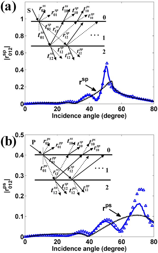
The enhanced polarization transformation of BSW is attributed to the multiple reflection of BSW in the two grooves. To describe the physical process of polarization transformation of BSW modes in the two grooves in detail, the Fresnel formula for the multilayer film is generalized to deal with the reflection and transmission of the BSW crossing the grooves. The groove can be considered as an equivalent interface. As the BSW propagates across the equivalent interface, the reflection, transmission and polarization transformation of BSW occur. A simplified model for multiple reflections of BSW between the two grooves is demonstrated in the inset of Fig. 6. The structure is then divided into three parts by two equivalent interfaces. The three parts of structure are numbered as 0, 1 and 2, respectively. The BSW is launched at the region 0. As the TE0-BSW propagates from region i to region j, and denote the reflection and transmission coefficients of TE0-BSW, respectively. and denote the polarization transformation coefficients of TE0-BSW to TM1-BSW, respectively. Similarly, as the TM1-BSW transmits from region i to region j, the terms , , and are used to denote the reflection, transmission and polarization transformation coefficients of TM1-BSW, respectively. From the simplified model and the defined coefficients, the generalized Fresnel formula of BSW can be expressed as:
| (3) |
where and denote the amplitude of the incident TE0-BSW and TM1-BSW, respectively. and denote the amplitude of the reflected TE0-BSW and TM1-BSW, respectively. As the BSW propagates across the two grooves, the reflection and polarization transformation coefficients of BSW can be defined:
| (4) |
In Eq. (3), the terms and denote the matrix of reflection and transmission coefficients at the first groove, i.e. the first equivalent interface.
| (5) |
The matrix M and S describe the multiple reflection of BSW between the two equivalent interfaces.
| (6) |
| (7) |
Here, the terms and are the longitudinal wavenumber of TE0-BSW and TM1-BSW along the X axis, respectively. ky is the transverse wavenumber of BSW along the Y axis. Then, the reflection intensities Rss and Rpp can be expressed as:
| (8) |
The polarization transformation intensities Rsp and Rps are given by:
| (9) |
The terms and denote the propagation power along the X axis for the reflected and incident BSW modes, respectively.
FIG. 6.
The amplitude of polarization transformation coefficients as a function of the incidence angle (a) for the polarization transformation of TE0-BSW to TM1-BSW, (b) for the polarization transformation of TM1-BSW to TE0-BSW. The solid lines denote the results obtained from Eq. (4), and the triangles denote the results obtained from the mode-matching method. The black dotted line denotes the polarization transformation coefficient of BSW for a single groove. The insets in the figure describe the simplified model of multiple reflection of BSW between the two grooves.
Figure 6(a) demonstrates the polarization transformation coefficient for the TE0-BSW propagating across two grooves versus the incidence angle. The solid line denotes the results obtained from the generalized Fresnel formula shown in Eq. (4), and the triangles denote the results obtained from the mode-matching method. To facilitate the comparison of the polarization transformation enhanced by two grooves, the transformation coefficient rsp of TE0-BSW for a single groove is also shown in the Fig. 6(a) with a dotted line. It is noted that the transformation coefficient of TE0-BSW can be enhanced or inhibited at the certain incidence angle relative to the coefficient rsp, which is attributed to the interference effect between the multiple beams. Similarly, the polarization transformation coefficient for the TM1-BSW propagating across two grooves versus the incidence angle is shown in Fig. 6(b). Compared to the transformation coefficient rps for a single groove, the coefficient can also be enhanced or inhibited at the certain incidence angle due to the interference effect from the reflected beams. The interference effects are sensitive to the phase factors of the reflected beam, which are well related to the wavenumber γs, γp and the separation distance Ld noted in Eq. (6) and Eq. (7). Then, this is a practical way to control the polarization transformation of BSW by adjusting the separation distance Ld between the grooves.
B. Anomalous reflection of BSW
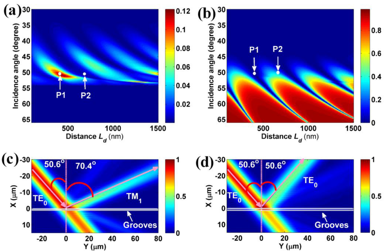
As the TE0-BSW propagates across the two grooves, Figures 7(a) and 7(b) demonstrates the polarization transformation intensity Rsp and the reflection intensity Rss as a function of the incidence angle and the separation distance Ld, respectively. With the increasing of the separation distance Ld, the Rsp and Rss exhibit the periodic changes arising from the constructive and destructive interference of reflected BSW beams. Furthermore, the changes of Rsp and Rss demonstrate the different periodicity due to the different interference effect noted in Eq. (6) and Eq. (7). It is feasible to achieve the completely polarization transformation in the reflected beam by adjusting the distance Ld, such as the point P1 labeled in Figs. 7(a) and 7(b). The point P1 means that the incidence angle of TE0-BSW is 50.6°, and the separation distance Ld is 410 nm. The Rsp can achieve the maximum value, and the value of Rss can become the minimum at this condition denoted by point P1. The electric field distribution of structure is calculated by mode-matching method at this condition, as shown in Fig. 7(c). The electric fields are extracted at the location z= 10 nm (X-Y plane). The incident TE0-BSW beam is modeled as the Gaussian shape with half width 10λ. λ= 633 nm is the incident wavelength. An interesting phenomenon is observed in the Fig. 7(c). The reflection angle of beam relative to the normal direction of the grooves is larger than the incident angle due to the excitation of TM1-BSW. The reflection angle of beam can be predicted from the Eq. (1), and is equal to 70.4°. This anomalous reflection is attributed to the polarization transformation of BSW, which is different from that arising from a metasurface or metagratings [30–33]. Then, the grooves can be used as the mode converter or polarization rotator for BSWs.
FIG. 7.
(a) Polarization transformation intensity Rsp and (b) the reflection intensity Rss of TE0-BSW versus the incidence angle and the separation distance Ld between grooves. The incidence angle of TE0-BSW is fixed at 50.6°. The electric field intensity distributions for different separation distance (c) Ld = 410 nm, (d) Ld = 680 nm. The wavelength of the incident light in vacuum is 633 nm.
In addition, the generation of TM1-BSW can also be inhibited by changing the distance Ld. For example, as the distance Ld is increased to 680 nm, the value of Rsp can becomes minimal due to the destructive interference of beams, but the value of Rss is increased corresponding to the point P2 labeled in Figs. 7(a) and 7(b). At this condition, the total electric field distribution is calculated and shown in Fig. 7(d). In this case, the structure demonstrates the normal reflection. The reflection angle of beam is equal to the incident angle. The polarization of reflection beam is the same as that of incident beam. Therefore, the separation distance Ld between the grooves is an efficient parameter to control the polarization transformation of BSW.
C. The effect of the multiple grooves
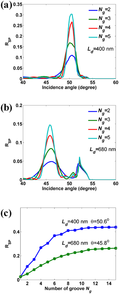
Moreover, it is noted that most of the energy of TE0-BSW can also transmit across the grooves as shown in Fig. 7(c). This part of energy can be further transformed to that of TM1-BSW by increasing the reflection of TE0-BSW, which can be achieved by increasing the number of the grooves. Figure 8(a) demonstrates the polarization transformation intensity Rsp versus the incidence angle with different number of grooves. The separation distance Ld between grooves is fixed at 400 nm. It is noted that the peak value of polarization transformation intensity Rsp around 50.6° is enhanced with the increasing of the number of grooves. As the distance Ld is increased to 680 nm, the constructive interference condition of polarization transformation Rsp is changed to 45.8°. With the increasing of the number of grooves, the peak value of polarization transformation intensity Rsp around 45.8° is also enhanced, which is shown in Fig. 8(b). To evaluate the maximum value of Rsp achieved by the multiple grooves, the peak values of Rsp at the different distance Ld versus the number of grooves are shown in Fig. 8(c). It is noted the values of Rsp can approach the stable values as the number of grooves Ng is larger than 10. The maximum polarization transformation efficiency of TE0-BSW to TM1-BSW achieved by the multiple grooves can approach 43%.
FIG. 8.
Polarization transformation intensity Rsp as a function of incidence angle with different numbers of grooves. The separation distance Ld between grooves is (a) 400 nm, (b) 680 nm. (c) The maximum transformation intensity Rsp versus the number of grooves Ng at the different separation distance Ld.
V. CONCLUSION
In conclusion, the polarization transformation between the TE and TM polarized BSW was achieved for the first time, which is through the multiple reflections from the grooves inscribed on a dielectric multilayer. By tuning the depth of groove and the separation distance between grooves, the polarization transformation efficiency can be reached as high as 43% attributed from the constructive interference of reflected beams. This value is much larger than the case of surface waves to free-space waves [34], where the transformation efficiency is only 0.4 %. And also, to the best of our knowledge, we have not noticed the reports on the polarization transformation of any surface waves. Due to this polarization transformation between the two polarized BSWs, an anomalous reflection phenomenon appears that the reflection angle of beam is different from the incidence angle. This phenomenon is different from the anomalous reflection induced by the widely investigated metasurfaces and provides a new means to manipulate the polarization and reflection of the electromagnetic waves [30–33]. Furthermore, the polarization transformation of BSW can be adjusted by changing the separation distance between grooves. This provides a feasible way to strengthen or inhibit the polarization transformation of BSW in the on-chip optical circuit system. The proposed method for polarization transformation not only can be used in the dielectric multilayer for BSWs, it is also applicable for the planar waveguide that containing two waveguide modes of different polarization states [35]. Our work will have potential applications in various areas, such as lab-on-a-chip devices, bio-sensing or imaging along with others. We have already reported that the different penetration depths above the surface can be used for selective sensing from the surface and bulk volume regions of the samples [35].
ACKNOWLEDGEMENTS
This work was supported by MOST (2013CBA01703 and 2016YFA0200601), NSFC (61427818 and 11374286), the Science and Technological Fund of Anhui Province for Outstanding Youth (1608085J02) and the Longshan academic talent research supporting program of SWUST (17LZX626). This work was also supported by grants from the National Institute of Health (GM107986, EB006521, EB018959, and OD019975).
References
- 1.Meade RD, Brommer KD, Rappe AM, and Joannopoulos JD, Electromagnetic Bloch Waves at The Surface of A Photonic Crystal, Phys. Rev. B 44,44–49 (1999). [DOI] [PubMed] [Google Scholar]
- 2.Yeh P, Yariv A, and Hong CS, Electromagnetic Propagation in Periodic Stratified Media. I. General Theory, J. Opt. Soc. Am 67, 423 (1977). [Google Scholar]
- 3.Sinibaldi A, Danz N, Descrovi E, Munzert P, Schulz U, Sonntag F, Dominici L, and Michelotti F, Direct Comparison of the Performance of Bloch Surface Wave and Surface Plasmon Polariton Sensors, Sens. Actuat. B-Chem 174, 292–298 (2012). [Google Scholar]
- 4.Badugu R, Nowaczyk K, Descrovi E, and Lakowicz JR, Radiative Decay Engineering 6: Fluorescence on One-Dimensional Photonic Crystals, Anal. Biochem 442, 83–96 (2013). [DOI] [PMC free article] [PubMed] [Google Scholar]
- 5.Toma K, Descrovi E, Toma M, Ballarini M, Mandracci P, Giorgis F, Mateescu A, Jonas U, Knoll W, and Dostalek J, Bloch-Surface Wave-Enhanced Fluorescence Biosensor, Biosens. Bioelectron 43,108–114 (2013). [DOI] [PubMed] [Google Scholar]
- 6.Pirotta S, Xu XG, Delfan A, Mysore S, Maiti S, Dacarro G, Patrini M, Galli M, Gutzzetti G, Bajoni D, Sipe JE, Walker GC and Liscidini M, Surface-Enhanced Raman Scattering in Purely Dielectric Structures via Bloch Surface Waves, J. Phys. Chem. C 117,6821–6825 (2013). [Google Scholar]
- 7.Descrovi E, Sfez T, Quaglio M, Brunazzo D, Dominici L, Michelotti F, Herzig HP, Martin OJF, and Giorgis F, Guided Bloch Surface Waves on Ultrathin Polymeric Ridges, Nano Lett 10, 2087–2091 (2010). [DOI] [PubMed] [Google Scholar]
- 8.Angelini A, Lamberti A, Ricciardi S, Frascella F, Munzert P, De Leo N, and Descrovi E, In-Plane 2D Focusing of Surface Waves by Ultrathin Refractive Structures, Opt. Lett 39, 6391–6393 (2014). [DOI] [PubMed] [Google Scholar]
- 9.Angelini A, Lamberti A, Ricciardi S, Frascella F, Munzert P, De Leo N, and Descrovi E, In-Plane 2D Focusing of Surface Waves by Ultrathin Refractive Structures, Opt. Lett 39, 6391–6393 (2014). [DOI] [PubMed] [Google Scholar]
- 10.Angelini A, Barakat E, Munzert P, Boarino L, De Leo N, Enrico E, Giorgis F, Herzig HP, Pirri CF, and Descrovi E, Focusing and Extraction of Light Mediated by Bloch Surface Waves, Sci. Rep 4,5428 (2014). [DOI] [PMC free article] [PubMed] [Google Scholar]
- 11.Angelini A, Munzert P, Enrico E, De Leo N, Scaltrito L, Boarino L, Giorgis F, and Descrovi E, Surface-Wave-Assisted Beaming of Light Radiation from Localized Sources, ACS Photonics 1, 612–617 (2014). [Google Scholar]
- 12.Sinibaldi A, Fieramosca A, Rizzo R, Anopchenko A, Danz N, Munzert P, Magistris C, Barolo C, and Michelotti F, Combining Label-Free and Fluorescence Operation of Bloch Surface Wave Optical Sensors, Opt. Lett 39, 2947–2949 (2014). [DOI] [PubMed] [Google Scholar]
- 13.Gao J, Sarangan AM, and Zhan Q, Polarization Multiplexed Fluorescence Enhancer using a Pixelated One-Dimensional Photonic Band Gap Structure, Opt. Lett 37, 2640–2642 (2012). [DOI] [PubMed] [Google Scholar]
- 14.Soboleva V, Moskalenko VV, and Fedyanin AA, Giant Goos-Hänchen Effect and Fano Resonance at Photonic Crystal Surfaces, Phys. Rev. Lett 108, 123901 (2012). [DOI] [PubMed] [Google Scholar]
- 15.Badugu R, Mao JY, Blair S, Zhang DG, Descrovi E, Angelini A, Huo YP, and Lakowicz JR, Bloch Surface Wave-Coupled Emission at Ultraviolet Wavelengths, J. Phys. Chem C 120, 28727–28734 (2016). [DOI] [PMC free article] [PubMed] [Google Scholar]
- 16.Maier SA, Plasmonics: Fundamentals and Applications (Springer: New York, 2007). [Google Scholar]
- 17.Raether H, Surface Plasmons on Smooth and Rough Surfaces and on Gratings (Springer-Verlag; Berlin Heidelberg, 1988). [Google Scholar]
- 18.Lin J, Dellinger J, Genevet P, Cluzel B, de Fornel F, and Capasso F, Cosine-Gauss Plasmon Beam: A Localized Long-Range Nondiffracting Surface Wave, Phys. Rev. Lett 109, 093904 (2012). [DOI] [PubMed] [Google Scholar]
- 19.Bharadwaj P, Bouhelier A, and Novotny L, Electrical Excitation of Surface Plasmons, Phys. Rev. Lett 106, 226802 (2011). [DOI] [PubMed] [Google Scholar]
- 20.Yu L, Barakat E, Sfez T, Hvozdara L, Di Francesco J, and Herzig HP, Manipulating Bloch Surface Waves In 2D: A Platform Concept-Based Flat Lens, Light: Sci. Appl 3, 124 (2014). [Google Scholar]
- 21.Born M and Wolf E, Principles of Optics, 7th edition (Cambridge University Press; 1999). [Google Scholar]
- 22.Zhan QW, Cylindrical vector beams: from mathematical concepts to applications, Adv. Opt. Photonics 1, 1–57 (2009). [Google Scholar]
- 23.Yao AM and Padgett MJ, Orbital angular momentum: origins, behavior and applications, Adv. Opt. Photonics 3, 161–204 (2011). [Google Scholar]
- 24.Alferness RC and Buhl LL, Waveguide electro-optic polarization transformer, Appl. Phys. Lett 38, 655–657 (1981). [Google Scholar]
- 25.Heidrich H, Albrecht P, Hamacher M, Nolting HP, Schroeter-Janssen H, and Weinert CM, Passive mode converter with a periodically tilted InP/GaInAsP rib waveguide, IEEE photonics tech. Lett 4, 34–36 (1992). [Google Scholar]
- 26.Derudder H, Olyslager F, De Zutter D, and Van den Berghe S, Efficient mode-matching analysis of discontinuities in finite planar substrates using perfectly matched layers, IEEE T. Antenn. Propag 49, 185–195 (2001). [Google Scholar]
- 27.Bienstman P, Rigorous and efficient modelling of wavelength scale photonic components, Ph.D. thesis, Ghent University, (2001). [Google Scholar]
- 28.Rumpf RC, Design and optimization of nano-optical elements by coupling fabrication to optical behavior, Ph.D. thesis, University of Central Florida, (2006). [Google Scholar]
- 29.See Supplemental Material at for more discussions on the simulation details using FDFD method [Google Scholar]
- 30.Yu NF and Capasso F, Flat Optics with Designer Metasurfaces, Nat. Mater 13,139–150 (2014). [DOI] [PubMed] [Google Scholar]
- 31.Kildishev AV, Boltasseva A, and Shalaev VM, Planar Photonics with Metasurfaces, Science 339, 1232009 (2013). [DOI] [PubMed] [Google Scholar]
- 32.Yu N, Genevet P, Kats MA, Aieta F, Tetienne JP, Capasso F, and Gaburro Z, Light Propagation with Phase Discontinuities: Generalized Laws of Reflection and Refraction, Science 334, 333–337 (2011). [DOI] [PubMed] [Google Scholar]
- 33.Ra’di Y, Sounas DL, and Alù A, Metagratings: Beyond the Limits of Graded Meta surfaces for Wave Front Control, Phys. Rev. Lett 119, 067404 (2017). [DOI] [PubMed] [Google Scholar]
- 34.Stegeman GI, Glass NE, Maradudin AA, Shen TP, and Wallis RF. Fresnel relations for surface polaritons at interfaces. Opt. Lett 8, 626–628 (1983). [DOI] [PubMed] [Google Scholar]
- 35.Wang R, Zhang D, Zhu L, Wen X, Chen J, Kuang C, Liu X, Wang P, Ming H, Badugu R, and Lakowicz JR, Selectable Surface and Bulk Fluorescence Imaging with Plasmon-Coupled Waveguides, J. Phys. Chem C 119, 22131–22136 (2015). [DOI] [PMC free article] [PubMed] [Google Scholar]


