Abstract
Few systematic structure–property-processing correlations for directionally freeze-cast biopolymer scaffolds are reported. Such correlations are critical to enable scaffold design with attractive structural and mechanical cues in vivo. This study focuses on freeze-cast collagen scaffolds with three different applied cooling rates (10, 1, and 0.1°C/min) and two freezing directions (longitudinal and radial). A semi-automated approach for structural characterization of fully hydrated scaffolds by confocal microscopy is developed to facilitate an objective quantification and comparison of structural features. Additionally, scanning electron microscopy, and compression testing are performed longitudinally and transversely. Structural and mechanical properties are determined on dry and fully hydrated scaffolds. Longitudinally-frozen scaffold have aligned and regular pores while those in radially-frozen ones exhibit greater variations in pore geometry and alignment. Lamellar spacing, pore area, and cell wall thickness increase with decreasing cooling rate: in longitudinally-frozen scaffolds from 25 μm to 83.5 μm, 814 μm2 to 8,452 μm2, and 4.21 μm to 10.4 μm, and in radially-frozen ones, from 69 μm to 116 μm, 7,679 μm2 to 25,670 μm2, and 6.18 μm to 13.6 μm, respectively. Both longitudinally- and radially-frozen scaffolds possess higher mechanical property values, when loaded parallel rather than perpendicular to the ice-crystal growth direction. Modulus and yield strength range from 779–4,700 kPa and 38–137 kPa, respectively, as a function of cooling rate and freezing direction. Collated, the correlations obtained in this study enable the custom-design of freeze-cast collagen scaffolds, which are ideally suited for a large variety of tissue regeneration applications.
Keywords: confocal microscopy, porosity, correlations, radial, longitudinal
1. Introduction
Little reported, but of particular importance for a biomaterial scaffold’s successful integration into the host tissue, are its structure and mechanical performance in both the dry and fully hydrated states (Ashworth et al., 2014). Scaffolds are hydrated, when surgically handled, during implantation (Anderson et al., 2008; Rahmanian-Schwarz et al., 2014) and in situ, so that a knowledge of the scaffold properties in the fully hydrated state are of particular importance. In this study, we focus on confocal microscopy (CM) as a means of biopolymer scaffold characterization in the fully hydrated state to illustrate a new CM-based method for the semi-automated rigorous quantification of pore architecture and morphology. Highlighted is, how the new technique complements strengths of scanning electron microscopy (SEM) such as a high resolution and depth of field (Deville, 2017; Ratner et al., 2004) and how it helps overcome its weaknesses such as the typical limitation to the imaging of dry samples (Bozkurt et al., 2007; Divakar et al., 2018, 2017; Francis et al., 2017, 2013; Lien et al., 2009; Loh and Choong, 2013; Re et al., 2015; Scotti and Dunand, 2018; Yin et al., 2018a).
We apply CM to determine structure-property-processing correlations in fully hydrated freeze-cast Type I bovine Achilles tendon collagen scaffolds. Freeze casting is a manufacturing technique, with which highly porous scaffolds can be manufactured from biopolymers whose hierarchical architecture can be controlled at multiple length scales to produce nano-, micro-, and macro-features that are known to play key roles in the successful biomaterial-tissue integration in a given clinical application (Bozkurt et al., 2012; Deville, 2017; Gibson et al., 2010; Riblett et al., 2012; Schoof et al., 2001; Scotti and Dunand, 2018; von Heimburg et al., 2001; Wegst et al., 2015, 2010). Collagen is an attractive biomaterial for tissue regeneration (Bozkurt et al., 2012, 2007; Chattopadhyay and Raines, 2014; Divakar et al., 2018, 2017; Lister, 1881; Macewen, 1881; Mohan et al., n.d.; Schoof et al., 2001). Its structural (e.g. degree of fibrillation), mechanical (e.g. stiffness, strength) and functional (e.g. cell adhesion) properties are known to be affected and determined by structural self-assembly processes that occur during processing (Bozkurt et al., 2007; Davidenko et al., 2012; Kuberka et al., 2002; O’Brien et al., 2005; Schoof et al., 2001, 2000; von Heimburg et al., 2001).
The collagen scaffolds were freeze cast with applied cooling rates of 10 °C/min, 1 °C/min, and 0.1 °C/min in PTFE molds (with a copper bottom) and aluminum molds (with a PTFE bottom) that result in a preferentially longitudinal or radial freezing direction, respectively. Performance-relevant structural parameters, such as overall porosity, pore morphology (e.g. pore area, long and short pore axes, pore aspect ratio), and the cell wall thickness were determined on the fully hydrated samples using a newly developed, semi-automated quantitative method based on Imaris (8.4.1) software (Bitplane, Belfast, UK). The mechanical properties (e.g. stiffness, strength, toughness) of the dry and fully hydrated samples were determined on cylindrical samples in compression both parallel and perpendicular to the cylinderical axis. Quantitative structure-property-processing correlations were established.
The new CM-based approach was found to offer a reliable and reproducible means for the characterization of scaffolds with a complex hierarchical pore architecture and offers a faster, more objective alternative to manual techniques for structural characterization, which are typically limited to a smaller number of pores than that achievable by a semi-automated approach (Re et al., 2015). The newly obtained results and structure-property-processing correlations allow to further streamline the process of rapid custom-design and manufacture of new tissue scaffolds; in doing so, structural and mechanical properties can be custom-designed to invoke the desired in vivo host response (Brown and Badylak, 2013; Madden et al., 2010; Ratner et al., 2004; van Tienen et al., 2002).
2. Materials and Methods
2.1. Slurry Preparation
For freeze casting, a 2% (w/v) collagen slurry was prepared by adding 2 g of Type I fibrous bovine tendon collagen powder (Advanced Biomatrix Inc., San Diego, CA) to 0.05 M acetic acid, raising to a total volume of 100 mL, refrigerating the mixture for at least 12 hours, and homogenizing (Fisher Scientific™ Homogenizer 152; Fisher Scientific International, Inc., Hampton, NH) thoroughly (at ~ ¾ maximum rpm) for 1.5 hours in an ice bath. Prior to freeze casting, slurries (≥ 10 mL) were shear mixed for 3 minutes at 2200 rpm (Speed Mixer™, DAC 150FVZ-K, FlackTek, Landrum, SC).
2.2. Freeze casting
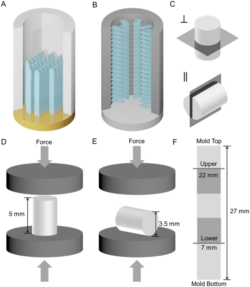
To freeze cast the scaffolds, the collagen slurry was injected with a syringe and needle (161/2 gauge) into the 4 mm diameter cylindrical bores of either PTFE molds (25.4 mm diameter; 30 mm length total length; mold bottom: copper) for longitudinal freezing or aluminum molds (25.4 mm diameter; 45 mm total length; mold bottom: PTFE) for radial freezing (Figure 1). The slurries were frozen on the copper coldfingers of a standard freeze-casting system(Wegst et al., 2010), at applied cooling rates of 10°C/min, 1°C/min, or 0.1°C/min. Once the samples were fully solidified, the molds were equilibrated to −20 °C in a freezer (HF-5017W-PA, VWR, Radnor, PA) prior to sample punch-out with an Arbor press for lyophilization at 0.008 mBar (−85 °C cooling coil temperature) for at least 24 hours in a Freezone 6 Plus system (Labconco, Kansas City, MO).
Figure 1.
(A) longitudinal and (B) radial freeze casting; (C) transverse (top) and longitudinal (bottom) imaging planes; (D) longitudinal and (E) radial compression loading directions; (F) upper and lower imaging planes and mechanical testing sample locations on a full-length scaffold.
2.3. Scaffold Crosslinking
For cross-linking, the freeze-cast and lyophilized collagen-based scaffolds were immersed in a solution of 33 mM 1-Ethyl-3-(3-dimethylaminopropyl) carbodiimide (EDC) and 6 mM N-hydroxysuccinimide (NHS) (both Sigma-Aldrich, St. Louis, MO) with 200 proof ethanol as the solvent, and stirred for 6 hours at room temperature (Pieper et al., 1999). To remove any residual crosslinking agents, the scaffolds were immersed in fresh batches of distilled water and gently stirred in three wash cycles (1 hr, 12 hrs, and 1 hr). Before each wash cycle, samples were gently palpated to aid the removal of absorbed solution. Finally, the samples were immersed and fully hydrated in distilled water before flash freezing in liquid nitrogen, and lyophilization at 0.008 mBar (−85 °C cooling coil temperature) for at least 24 hours (Freezone 6 Plus, Labconco, Kansas City, MO).
2.4. Scaffold Density and Porosity
Overall scaffold porosity P0 for the cylindrical scaffolds (Eq.1) was determined from the density of the freeze-cast scaffold, ρ0, and the theoretical density of the collagen of which the scaffold is composed, ρS = 1.30 mg/mm3 (Wiederhorn and Reardon, 1952).
| (Eq. 1) |
where the scaffold density, ρ0, was calculated for each cylindrical sample as scaffold mass per scaffold volume, with the volume calculated from scaffold diameter and length measurements made using an optical microscope (Leica Optical Microscope M205C, Leica Camera AG, Wetzlar, Germany). A sample size of n = 10 was used for overall scaffold porosity and density calculations.
For comparison, the overall image-based scaffold porosity, PI, was determined based on the analysis of high magnification confocal images and measurements of the cell wall area, AS, and the pore area, AP, using the Imaris (8.4.1) image analysis software (Bitplane, Belfast, UK):
| (Eq. 2) |
Standard deviation (S.D.), standard error (S.E.), confidence interval (C.I.) calculations and graphing were performed using Origin 9.1 (OriginLab Corporation, Northampton, MA). For porosity calculations based on image analysis in the fully hydrated (confocal microscopy) state, individual pores were analyzed.
2.5. Confocal and Scanning Electron Microscopy
For confocal microscopy (CM), scaffolds were analyzed in both the lower (7 mm from mold bottom) and upper regions (22 mm from mold bottom) of the scaffold, in which the local cooling rates are expected to be different.
Samples from the upper region were biopsy punched (2 mm) in the frozen state from the 4 mm diameter cylindrical samples before lyophilization and analysis. These central 2 mm diameter regions of the scaffolds parallel in size and shape the cylindrical samples prepared and used for in vivo studies (Divakar et al., 2018, 2017). Transverse and longitudinal scaffold sections (Figure 1) were prepared using a razor blade (Astra Superior Platinum) and custom-designed 3D printed miter boxes. For imaging, the cylinders were stained in 0.05 mg/mL fluorescein/PBS solution for 24 hrs on an orbital shaker (VWR International Company, Radnor, PA). Immediately before imaging, samples were first gently palpated (at least 3 times) to remove residual fluorescein solution, then washed in fresh PBS. Both transverse and longitudinal cross-sections of the samples were imaged with a Nikon A1R Confocal Microscope (Nikon Corporation, Tokyo, Japan) at a 488 nm excitation wavelength and 525/50 nm emission filter; samples were placed on a #1.5 coverslip (0.16–0.19 mm); no Z-stacking was used. SEM micrographs were obtained with a FEI Scios2 FEG SEM (FEI Company, Hillsboro, OR) after gold sputter coating.
The Imaris (8.4.1) imaging software (Bitplane, Belfast, UK) was used to analyze the transverse confocal micrographs. For longitudinally-frozen scaffolds, analysis was performed on high-magnification micrographs obtained for each sample type; for radially-frozen scaffolds, analysis was performed on micrographs of the entire cross-section obtained for each sample type. Different imaging depths were chosen to accommodate the structural differences between the two freezing directions.
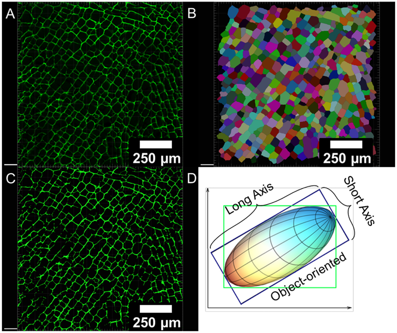
The analysis was performed using the Imaris (8.4.1) “Cell module” (Figure 2) using following criteria: i) “cell-only detection,” since the scaffolds’ “cell-like” pores are empty and do not contain nuclei; ii) “cell boundary” detection, because the demarcation of the cell walls is of interest; iii) an estimate of 10–25 μm as the minimum length-wise pore size for each image; iv) default “cell intensity,” and adjusted “quality threshold” until most pores were correctly segmented; v) pores that extended beyond the image (partial pores) were filtered out with a built-in function; vi) upon visual inspection, if a pore was segmented incorrectly, it was fused or deleted to create a more accurate collection of demarcated pores for every image; vii) the number of pixels for each pore (converted to units of length based on pixel dimensions) as well as object-oriented (Figure 2) long and short axes were calculated with built-in software functions; the pore aspect ratio was calculated as the long axis divided by the short axis.
Figure 2.
(A) confocal micrograph; (B) automated pore identification for size and aspect ratio measurements using the Imaris (8.4.1) software; (C) image mask created based on absolute intensity used for image-sbased porosity, pore size (area and axes), and cell wall thickness measurements; (D) object-oriented method (in blue box) for long and short axes measurements for each pore, which is independent of image orientation (adapted from Imaris 8.4.1).
To determine the pore area without the cell wall, the “Surfaces” module was used to create a mask based on absolute intensity, which was then subtracted from the original demarcated image (Figure 2). To calculate image-based porosity, PI, the area of the mask was considered the AS and the area of the total image was considered the sum of AS and AP to apply Eq. 2. Cell wall thickness was approximated using the “Filaments” module to analyze a mask of a representative confocal micrograph. Pore size analysis was performed on three representative confocal images for each scaffold type; the number of pores analyzed for each of the sample types was as follows (Table 1):
Table 1.
Number of pores, n, analyzed per scaffold type and region
| Scaffold Type | Applied Cooling Rate (°C/min) | Lower n | Upper n |
|---|---|---|---|
| Longitudinal | 10 | 4688 | 1548 |
| 1 | 2351 | 1117 | |
| 0.1 | 542 | 409 | |
| 10 | 683 | 294 | |
| Radial | 1 | 707 | 344 |
| 0.1 | 411 | 172 |
2.6. Compression Testing
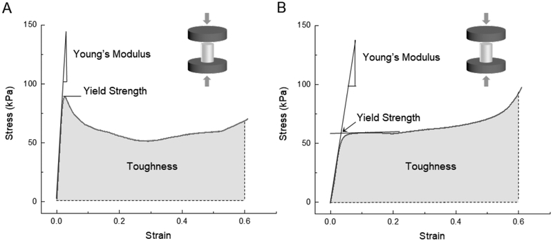
Compression tests were performed parallel and perpendicular to the cylinder axis on both dry and fully hydrated samples of 5 mm length and 4 mm diameter. Dry samples were tested at ambient conditions (22–24 °C and r.h. 52–55%) on an Instron 5498 (Instron, Norwood, MA) with a 50 N load cell; fully hydrated samples were soaked for 24 hours in PBS before testing in longitudinal compression with a 5 N load cell and a cross-head speed of 0.05 mm.s−1 thus at a strain rate of 0.01/s. Compression tests were chosen, because scaffolds, such as those described here, tend to be used in applications in which they are loaded in compression and bending, rather than in tension, and because they typically fail in compression, also when loaded in bending (Figure 3). For samples tested parallel to the cylinder axis, the modulus (the slope of initial linear region), yield strength (yield point, if present, otherwise the intersection of the initial linear slope and the slope of the initially linear plateau region), and toughness (work to 60% strain) were determined from the stress-strain curves as indicated in Figure 3. Dry longitudinal compression testing (n = 3–5) was performed for the six scaffold types. In contrast to the longitudinal tests, radial testing involved a constantly varying cross-sectional area and complex stress- and strain distributions within the samples; thus, tests were performed only for direct comparison; no mechanical properties were determined. As expected, fully hydrated samples had significantly lower properties than their dry counterparts.
Figure 3.
Typical stress-strain curves for (A) longitudinally and (B) radially-frozen cylindrical scaffolds in the loading direction parallel to the cylindrical axis (longitudinal compression).
3. Results
3.1. Scaffold Structure by Confocal and Scanning Electron Microscopy
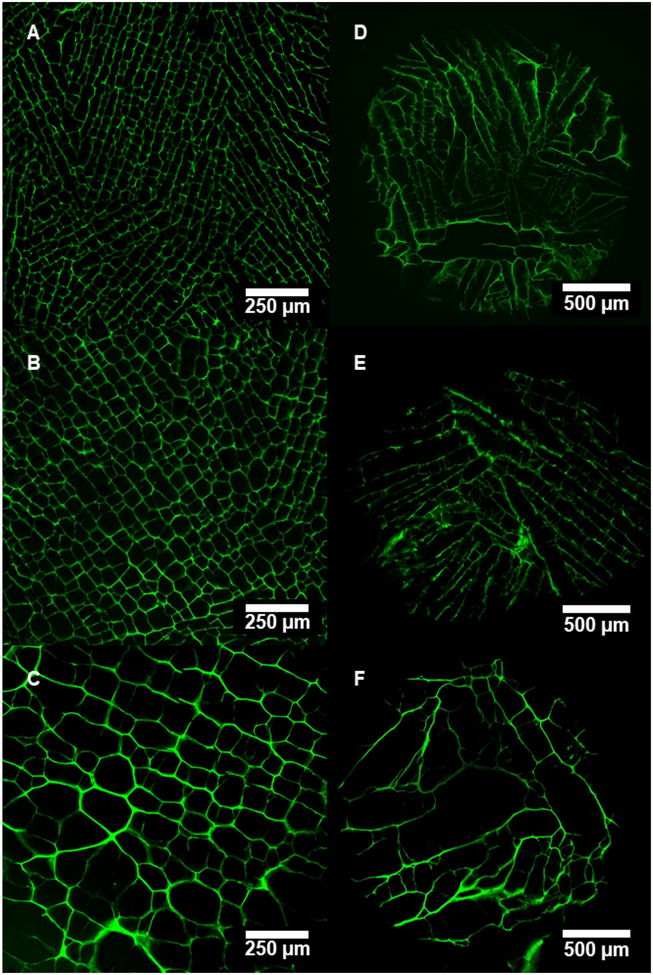
The structural characterization of the fully hydrated Type I collagen scaffolds revealed significant differences in pore size and morphology (Figures 4–7) for the three applied cooling rates (10 °C/min, 1 °C/min, and 0.1 °C/min), the two mold types and configurations (PTFE versus aluminum) that result in a predominantly longitudinal or radial thermal gradient and freezing direction, respectively, and the upper and lower scaffold regions. The dry scaffold porosity for the different scaffolds types remained relatively similar, while there was a slight decrease in density from the lower to upper scaffold regions (Table 2).
Figure 4.
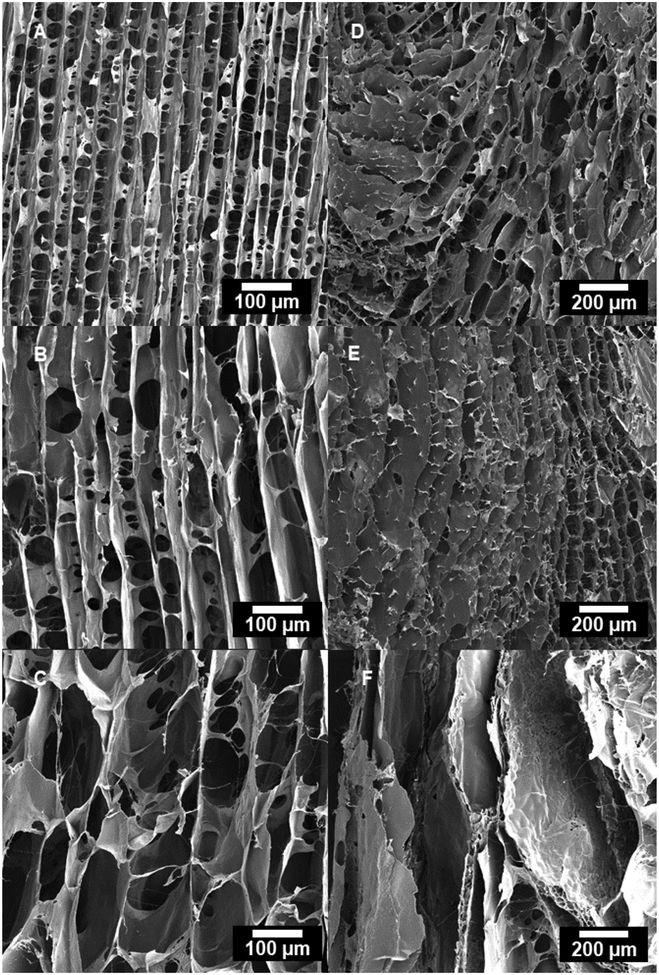
Confocal micrographs of transverse cross-sections in the upper region of scaffolds freeze-cast longitudinally (A: 10 °C/min, B: 1 °C/min, C: 0.1 °C/min) and radially (D: 10 °C/min, E: 1 °C/min, F: 0.1 °C/min).
Figure 7.
SEM micrographs of longitudinal cross-sections in the upper region of scaffolds freeze-cast longitudinally (A: 10 °C/min, B: 1 °C/min, C: 0.1 °C/min) and radially (D: 10 °C/min, E: 1 °C/min, F: 0.1 °C/min).
Table 2.
Density and porosity (mean ± S.D.) for lower and upper regions of the dry scaffolds. Porosity calculated with Eq. 1, assuming a solid collagen density of 1.30 mg/mm3. (Wiederhorn and Reardon, 1952)
| Scaffold Type | Applied Cooling Rate (°C/min) | Lower | Upper | ||
|---|---|---|---|---|---|
| Density (mg/cm3) | Calculated Porosity, P0 (%) | Density (mg/cm3) | Calculated Porosity, P0 (%) | ||
| 10 | 27.9 ± 1.6 | 97.9 ± 0.12 | 25.6 ± 1.4 | 98.0 ± 0.10 | |
| Longitudinal | 1 | 28.5 ± 1.5 | 97.8 ± 0.11 | 25.4 ± 3.2 | 98.0 ± 0.25 |
| 0.1 | 28.6 ± 1.3 | 97.8 ± 0.10 | 27.0 ± 5.2 | 97.9 ± 0.40 | |
| 10 | 22.9 ± 1.4 | 98.2 ± 0.11 | 23.1 ± 0.87 | 98.2 ± 0.067 | |
| Radial | 1 | 22.8 ± 2.5 | 98.2 ± 0.19 | 22.4 ± 0.77 | 98.3 ± 0.059 |
| 0.1 | 24.8 ± 0.61 | 98.1 ± 0.047 | 23.7 ± 0.98 | 98.2 ± 0.075 | |
3.1.1. Longitudinally-frozen Scaffolds
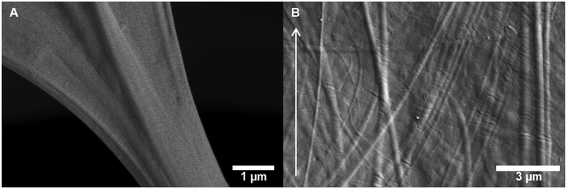
In the case of the longitudinally-frozen scaffolds, the porosity was highly aligned parallel to the freezing direction (Figures 4–7). High-resolution SEM micrographs of collagen scaffolds longitudinally frozen at 1 °C/min reveal a preferential alignment of collagen fibrils within the scaffold microstructure; in particular, aligned collagen fibers follow the curvature of fibrillar bridges and collagen fibers observed in the scaffold lamellae appear parallel to the freezing direction (Figure 8).
Figure 8.
High-resolution SEM micrographs of longitudinally freeze-cast (1 °C/min) collagen scaffolds revealing (A) fibrillar bridge connecting cell walls with aligned collagen fibers, and (B) nano- and microtopography created by collagen fibers in scaffold lamellae that are preferentially-aligned with the freezing direction (arrow).
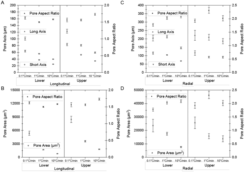
Both pore area and the cell wall thickness increased considerably—from 813 to 5372 μm2 (Table 1) and from 4.21 to 9.99 μm (Table 3), respectively—with a decreasing applied cooling rate (Figure 9); also moving from the lower region (close to the mold bottom) upwards, the pore area and the cell wall thickness increased with values ranging from 1809 to 8452 μm2 (Table 4) and 4.82 to 10.4 μm (Table 3), respectively. The cell walls were connected by numerous fibrillar bridges; the largest number of bridges per area were observed in the scaffolds longitudinally frozen at 10 °C/min (Figure 6A and Figure 7A).
Table 3.
Cell wall thickness (mean ± S.D.) for lower and upper regions of the fully hydrated scaffolds
| Scaffold Type | Applied Cooling Rate (°C/min) | Cell Wall Thickness (μm) | |
|---|---|---|---|
| Lower | Upper | ||
| Longitudinal | 10 | 4.21 ± 1.14 | 4.82 ± 1.57 |
| 1 | 5.28 ± 1.76 | 5.73 ± 1.87 | |
| 0.1 | 9.99 ± 6.63 | 10.4 ± 6.51 | |
| Radial | 10 | 6.18 ± 2.43 | 8.38 ± 3.76 |
| 1 | 8.3 ± 4.13 | 8.44 ± 3.84 | |
| 0.1 | 13.6 ± 5.89 | 11.8 ± 4.71 | |
Figure 9.
Pore length (long and short axis) and pore aspect ratio for the (A) longitudinally- and (C) radially-frozen scaffold types (mean ± 95% C.I.). Pore area (with the cell wall) and pore aspect ratio are plotted for the scaffold types (mean ± 95% C.I.), for both (B) longitudinally- and (D) radially-frozen scaffolds comparing the lower and upper scaffold regions.
Table 4.
Correlations between applied cooling rate and pore size for longitudinal freezing
| Lower | Upper | |||||
|---|---|---|---|---|---|---|
| k | n | R2 | k | n | R2 | |
| Saxis (k2, n2) | 39.2 | 0.203 | 0.995 | 53.5 | 0.191 | 0.999 |
| Pore Area (k3, n3) | 1956 | 0.410 | 0.985 | 3803 | 0.335 | 0.996 |
Figure 6.
Confocal micrographs of longitudinal cross-sections in the upper region of scaffolds freeze-cast longitudinally (A: 10 °C/min, B: 1 °C/min, C: 0.1 °C/min) and radially (D: 10 °C/min, E: 1 °C/min, F: 0.1 °C/min).
3.1.1. Radially-frozen Scaffolds
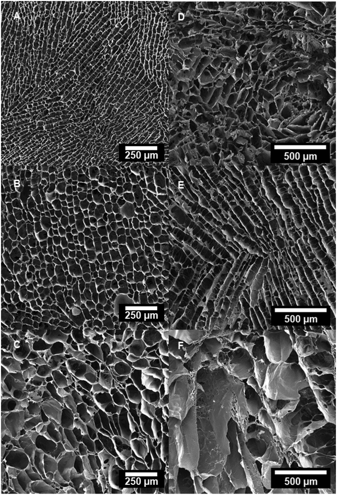
The same fundamental correlation of an increasing pore size and wall thickness with both decreasing applied cooling rate and increasing height from the mold bottom was observed in the radially-frozen scaffolds (Figures 4–7). However, the radial alignment and morphology of the pores was found to be less regular among different applied cooling rates; the most regular and continuous pore alignment was found in the scaffolds frozen at 1 °C/min (Figures 4E & 5E). Micrographs of longitudinal cross-sections of the radially frozen samples revealed that the porosity is not strictly radially aligned, but that the long pore axis forms an inclined angle with the mold surface (Figures 6E and 7E). A comparatively less homogenous pore morphology was observed in the case of applied cooling rates of 10 °C/min and 0.1 °C/min (Figures 4E, 4F, 5E, & 5F).
Figure 5.
SEM micrographs of transverse cross-sections in the upper region of scaffolds freeze-cast longitudinally (A: 10 °C/min, B: 1 °C/min, C: 0.1 °C/min) and radially (D: 10 °C/min, E: 1 °C/min, F: 0.1 °C/min).
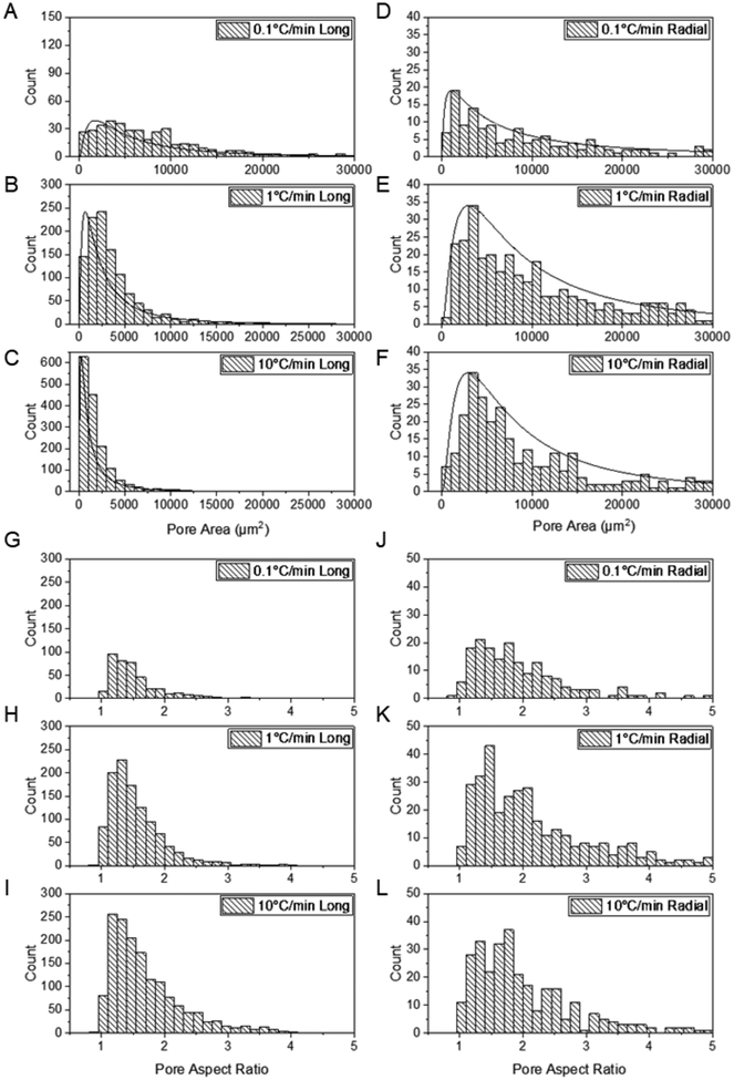
The pore area and pore aspect ratio distributions for all longitudinal and radial scaffold types are log-normal and thus skewed towards lower values (Figure 10). Because a decreasing cooling rate results in larger ice crystals and the polymer concentration remains almost constant, the same amount of solid needs to be accommodated in a considerably reduced overall cell wall length. Therefore, not only the pore area, and long and short pore axes but also the cell wall thickness increases along the freezing direction in the case of the longitudinally-frozen scaffolds. However, the pore aspect ratios remain almost constant. In the case of radially-frozen scaffolds, the pore area distribution is more varied, but the pore aspect ratio is generally higher than that in the longitudinally-frozen scaffolds (Figures 9 & 10).
Figure 10.
(A–F) Pore area (including the area of half of the cell wall thickness) distribution for the scaffolds frozen longitudinally and radially at three different applied cooling rates (0.1 °C/min, 1 °C/min, and 10 °C/min); pore aspect ratio (G-L) distribution for the longitudinally and radially-frozen scaffolds at the three different applied cooling rates (upper scaffold region).
3.2. Mechanical Properties in Compression
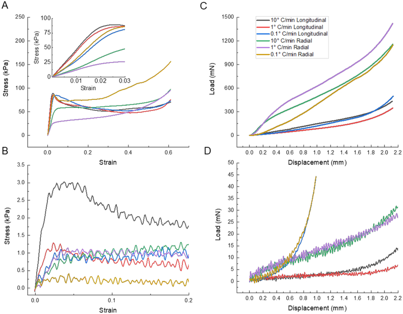
The mechanical tests performed in compression on the dry and fully hydrated Type I collagen scaffolds resulted in stress-strain curves (Figure 11) that are typical for cellular solids in general (Gibson et al., 2010; Gibson and Ashby, 1999), and directionally freeze-cast scaffolds in particular (Donius et al., 2014a; Hunger et al., 2013a; Meghri et al., 2010). Longitudinally-frozen samples and one radially-frozen type (0.1 °C/min) exhibited a distinct yield point, while the other samples did not (Figure 11). The significant differences in modulus, strength, and toughness observed for the samples freeze-cast at the three applied cooling rates (10 °C/min, 1 °C/min, and 0.1 °C/min), using two mold types and configurations (PTFE versus aluminum), reflect the scaffold anisotropies, the predominantly longitudinal or radial alignment of the fibrillary components that form the cell walls, the observed variations in cell wall thickness and pore size, and the cell wall material structure and properties that result from the specific processing conditions and resulting self-assembly phenomena.
Figure 11.
Typical compressive stress-strain curves for tests performed parallel to the long cylinder axis of samples from the upper regions of (A) dry (inset magnifies initial slope region) and (B) fully hydrated collagen scaffolds freeze cast at three different applied cooling rates (0.1 °C/min, 1 °C/min, and 10 °C/min). Typical compressive stress-strain curves for tests performed perpendicular to the long cylinder axis of samples from the upper regions of (C) dry and (D) fully hydrated collagen scaffolds.
In the case of longitudinally-frozen scaffolds, we found the modulus to decrease with a decreased applied cooling rate (from 4,700 kPa to 2,050 kPa); the opposite, if less pronounced, trend was observed (Figure 12) in the case of the yield strength (from 82.5 kPa to 93.3 kPa). In contrast, radially-frozen scaffolds showed an increasing modulus (from 779 kPa to 2,780 kPa) and strength (from 38.8 kPa to 137 kPa) with decreasing applied cooling rate (Figure 12). Longitudinally-frozen scaffolds loaded parallel to the cylinder axis were found to possess a two- to three-fold higher modulus (Figure 11) than radially-frozen scaffolds loaded in the same direction; radially-frozen samples loaded in the radial direction of the cylinder had higher properties than longitudinally-frozen samples loaded in this direction (Figure 11). Mechanical properties based on an evaluation of the load displacement curves are at least one magnitude lower in the fully hydrated state (Figure 11).
Figure 12.
Yield strength plotted versus modulus (mean ± S.E.) for the upper and lower regions of the scaffolds (A) longitudinally and (B) radially freeze-cast at three different applied cooling rates (0.1 °C/min, 1 °C/min, and 10 °C/min).
4. Discussion
Few systematic studies reporting structure-property-processing correlations for directionally ice-templated collagen scaffolds such as effects of applied cooling rate on scaffold pore size, cell wall thickness and to mechanical properties, have been reported, to date (Clearfield and Wei, 2016; Kuberka et al., 2002; Schoof et al., 2001, 2000). In addition, most of the work on directional freeze casting focuses on generating longitudinal anisotropy (Scotti and Dunand, 2018; Wegst et al., 2015, 2010). Radial anisotropy (Bai et al., 2015; Li and Dunand, 2011; Macchetta et al., 2009; Tang et al., 2014; Yin et al., 2018b, 2018a) has been a less emphasized area of investigation. In this study, strong correlations were observed between structure, mechanical properties, and processing conditions for anisotropic collagen scaffolds made with three applied cooling rates 0.1 °C/min, 1 °C/min, and 10 °C/min.
4.1. Scaffold Structure by Confocal Microscopy (CM)
In the light of the fact that biomedical materials are typically used in fully hydrated environments, it is critical to characterize their structure and mechanical performance under comparable conditions. Cell wall swelling and the resulting reduction in open and cell-accessible porosity cannot usually be predicted from SEM micrographs, since these are typically obtained when the scaffold is dry. Required is the imaging of the fully hydrated biomaterial by CM. A comparison of the pore morphologies of the collagen scaffolds in their dry (Figures 5 & 7) and their fully hydrated (Figures 4 & 6) states highlight the structural changes that occur after hydration. We conclude that ideally both imaging techniques should be combined for a fair and best-informed assessment of both structure-property-processing correlations and the scaffold’s promise for a given application.
Advantages of SEM over CM imaging are a considerably higher depth of field, magnification, and resolution that can be obtained. With the SEM, it is possible to investigate important structural features such as nano- and microtopographies of the cell walls that result from self-assembly processes during freeze casting (Figure 8). However, high resolution, precise, and quantitative image analysis such as that of the pore morphology, for example, is particularly challenging in thin-walled structures, because of their slight deformation during sample preparation, which in combination with the high depth of field, leads to artefacts, such as an overestimation of cell wall thickness, when the images are binarized for further analysis.
Advantages of CM over SEM imaging are that it enables the 2D imaging and quantitative structure analysis of scaffold cross-sections in the application-relevant fully hydrated state, when the cell walls are swollen. The results of the structural analysis demonstrate that low depth-of-field CM is a powerful technique for the rigorous quantitative imaging of fully hydrated collagen scaffolds and other biopolymer porous materials, which are either transparent or fluorescent. Using CM micrographs and the Imaris (8.4.1) software (Bitplane, Belfast, UK), the scaffold’s overall porosity and the pore morphology, defined by the long and short pore axes, pore aspect ratio, and cross-sectional pore area (with and without cell wall area), and cell wall thickness were quantified in a semiautomatic process. Advantages of this semi-automated over a manual approach are that individual pores can be analyzed more objectively and in larger numbers.
What is not possible with CM, despite the availability of z-stacking of a series of images and a penetration depth that can reach 100–200 μm, is a robust analysis of the 3D architecture of the collagen scaffolds to determine pore interconnectivity, for example. For such an analysis the pore sizes are too large and a truly tomographic 3D imaging method would be required. A tomographic data set would also offer virtual sectioning in any desired image plane, whereas CM relies on careful sample preparation to ensure imaging in a preferred orientation or direction. Where CM and tomographic imaging methods are comparable are pixel resolutions of about 1–5 μm obtainable with typical desktop systems and camera sizes.
Structurally, for all scaffold types, the long and short pore axes, the cross-sectional pore area, and the cell wall thickness, were found to increase with a decrease in the applied cooling rate; pore size and cell wall thickness also increased from the lower to upper scaffold regions, reflecting the decrease in local cooling rate in a given sample due to thermal losses. These trends are consistent with correlations between structure and processing in longitudinally freeze-cast materials in general (Hunger et al., 2013a; Scotti and Dunand, 2018; Wegst et al., 2015, 2010) and collagen, in particular (Kuberka et al., 2002; Schoof et al., 2001). Longitudinal freezing resulted in highly reproducible, regular honeycomb-like pore morphologies for all tested applied cooling rates. Radial freezing, while still highly reproducible in overall pore size distribution, yielded a more complex pore architecture and less regular pore alignment both along and across the cylinder axis. Both the longitudinally- and the radially-frozen samples exhibited a log-normal pore size distribution, which is expected for porous materials (Re et al., 2015; Scaffaro et al., 2012). The observed pore sixes (short pore axes) of 25 – 53 μm agree well with the values of 20 – 60 μm reported in the literature for collagen scaffolds made with an applied cooling rate of 1 – 10 °C/min (Bozkurt et al., 2012, 2007; Kuberka et al., 2002; Schoof et al., 2001, 2000; von Heimburg et al., 2001). We further show, that the pore size achieved with an applied cooling rate of 10 °C/min can be doubled to 83.5 ± 39.2 μm with a tenfold lower cooling rate of 0.1 °C/min.
Systematic trends and correlations become useful, when they allow predictions of performance and thus, the custom-design of new materials and structures. Traditionally, in the freeze-casting community, structural features, such as the lamellar spacing, λ (which in our case is equivalent to the short pore axis), are correlated with the freezing front velocity, v, during processing, where k1 and n1 are material and mold-specific quantities.
| (Eq. 3) |
Since the accurate measurement of the freezing front velocity for a given mold design and freezing setup is an elaborate undertaking that either requires specialized molds or cryo-X-ray tomography(Hunger et al., 2013b; Waschkies et al., 2011), it is more practical and useful to obtain correlations between structural features and the applied cooling rate. This is what we propose and report, here, for the case of longitudinal solidification, which results in a particularly reproducible and regular pore architecture.
In analogy to the expression of Eq. 3, we find as the correlation between the short axis of the pore, Saxis, and the applied cooling rate, Ċ:
| (Eq. 4) |
where Ċ is the applied cooling rate [°C/min], Saxis is the short axis of the pore [μm], and k2 and n2 are material and mold-specific quantities that describe the correlation for a given applied cooling rate and position along the length of the mold.
Similarly, we can describe the correlation between pore area, A, and the applied cooling rate, Ċ:
| (Eq. 5) |
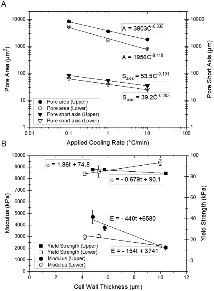
where A is the pore area (μm2), Ċ is the applied cooling rate [°C/min], and k3 and n3 are material and mold-specific quantities that describe the correlation for a given applied cooling rate and position along the length of the mold. We find strong correlations (Table 4) using the models described above (Figure 13), with constants that are consistent with literature values (Kuberka et al., 2002; Kurz and Fisher, 1981; van der Sman et al., 2013).
Figure 13.
(A) Pore area and short axis (mean ± S.E.) plotted versus applied cooling rate for the upper and lower regions of longitudinally frozen scaffolds; (B) yield strength and modulus (mean ± S.E.) plotted versus cell wall thickness for the scaffolds at the three different applied cooling rates.
A new observation is that the number of the fibrillar bridges between the cell walls, which are characteristic for fibrillary scaffolds such as those composed of collagen, decreases noticeably with decreasing applied cooling rate. Collagen fiber bridges form, when collagen fibrils are first aligned due to the shear flow that results from the volumetric expansion of the ice dendrites, then held in the increasingly viscous collagen slurry that self-assembles into the cell wall material. When the solidification has progressed so far that no further fiber flow is possible, and the fibers are bundled and firmly held in the solid, they are overgrown and integrated into the ice phase.
The lower the applied cooling rate, the longer the continuously upconcentrating collagen slurry remains viscous, thus the more time the fibrils have to disentangle, flow, and rearrange with a slight preference of a fibril alignment parallel to the freezing direction (Figure 8). Similarly, a lower applied cooling rate leaves more time for water-polymer interdiffusion, fibrillar and structural self-assembly, and a more effective removal of water from the paper-like collagen fiber mat that forms the cell walls of the scaffold. Preferential fiber alignment, fiber bridging, and differences in moisture content in the cell wall materials contribute to the observed differences in scaffold structure, on the one hand, and mechanical properties and the resulting overall mechanical performance of the scaffolds, on the other. All these features contribute, along with the difference in pore structure and alignment, to the considerable differences in structural regularity, features, and mechanical performance of longitudinally- and radially-frozen scaffolds.
4.2. Mechanical Properties in Compression
Correlating freezing conditions with structural features, we find that both the pore area and the cell wall thickness increase with a decreasing applied cooling rate and that consistently, the modulus is higher in the upper scaffold region, where the pore area and as a result also the cell wall thickness are larger due to a decreased local cooling rate. The situation is more complex for correlations of structure, properties, and processing conditions for the different applied cooling rates, and the longitudinally- and radially-frozen samples, respectively.
4.2.1. Mechanical Properties of Longitudinally-Frozen Scaffolds
Correlating mechanical properties with structural features (Table 5) in longitudinally frozen samples (Figure 13), we find that the modulus decreases while the yield strength increases slightly with increasing pore size and cell wall thickness, when loading the samples parallel to their cylinder axis, thus parallel to the freezing direction and pore alignment.
Table 5.
Correlations between cell wall thickness, t, and mechanical properties for longitudinally freezing
| Lower | Upper | |||||
|---|---|---|---|---|---|---|
| m | b | R2 | m | b | R2 | |
| Modulus (mE, bE) | 154 | 3740 | 0.952 | 440 | 6580 | 0.960 |
| Yield Strength (mσ, bσ) | 1.8 | 74.8 | 0.999 | −0.679 | 90.1 | 0.984 |
The explanation for these structure-property correlations are differences in overall structural features and the mechanical properties of the cell wall material, which result from differences in fibrillar self-assembly and preferential fiber alignment, as described above. The mechanical testing results suggest that the higher number of fibrillar bridges combined with a larger number of domains found in samples with thinner cell walls result in a significant stiffening effect. This trend is more pronounced in the case of the upper scaffold region in longitudinally frozen samples, because structurally it is more regular than the lower region. These findings suggest a correlation between cell wall thickness, t (μm), and scaffold mechanical properties (Eqs. 6 and 7), such as modulus, E (kPa), and yield strength, σ (kPa), which can be determined from the experimental results as:
| (Eq. 6) |
and
| (Eq. 7) |
where mE and bE and mσ and bσ, respectively, are quantities that are material and mold-specific that describe the correlation for a given applied cooling rate, Ċ, and position along the length of the mold.
Thus, the applied cooling rate not only affects pore morphology, but also cell wall material properties: the slower the applied cooling rate, the more effective molecular and fibrillar packing and drying of the self-assembled structure (Donius et al., 2014a; Tong et al., 1984). Additionally, in the case of fibrillar materials like the collagen of this study, we observe with a decreasing applied cooling rate, a decreasing number of fibrillar bridges that connect the cell walls. Features like these fibrillar bridges have been observed to enhance structural and mechanical performance in freeze-cast and porous materials (Davidenko et al., 2016; Donius et al., 2014a, 2014b; Francis et al., 2017, 2013; Riblett et al., 2012).
In the light of the above, the overall lower values for the modulus can be explained by the lower degree of pore alignment and smaller pore sizes and cell wall thicknesses, which we observed in the lower region of higher density near the sample bottom plate compared to the upper region of slightly (~10%) lower density for all scaffold types (Table 2). This result is a little counterintuitive, since fundamentally, the modulus of cellular solids is expected to increase with increasing density (Gibson et al., 2010; Gibson and Ashby, 1999). That this is not the case, suggests that architectural structural features resulting from fibrillation and fiber self-assembly in the cell wall material play an important and, in this case, dominant role.
Yield strength values slightly increase with decreasing freezing rate; the values remain almost constant along the length of the sample, despite a decrease in density from the bottom to the top (Figure 12). Thus, the correlations between strength and cell wall thickness are not as clear as for the modulus. As before, this is partly attributed to the compensation of the lower scaffold density by architectural features, such as thicker cell walls, in the case of the lower freezing rate, and cell wall bridging, in the case of a higher freezing rate (Figures 6 & 7 and Table 3).
4.2.2. Mechanical Properties of Radially-Frozen Scaffolds
In radially-frozen scaffolds a decrease in the applied cooling rate resulted in an increase in stiffness and strength as a result of both an increase in cell wall thickness and the creation of the angled pore alignment, respectively. The earlier observed loss in stiffness and strength through a lower fibrillar reinforcement at the slower freezing rate was likely dominated by this change in microstructure. Scaffolds radially frozen at 1°C/min possess higher values for stiffness, strength, and toughness in the lower region than in the upper region; also, this outcome is likely a result of a lower degree of fibrillar bridging, and insufficient cell wall thickening to compensate (Table 3). The highest strength of all scaffold types (radial and longitudinal) was observed in scaffolds radially frozen at 0.1°C/min. This is most likely due to the high cell wall thickness at the low applied freezing rate and a favorable alignment of the angled cell wall with the loading direction (Figures 6F & 7F), the latter being supported by a stress-strain curvature similar to those obtained with longitudinally-frozen scaffolds.
5. Conclusion
Structure-property-processing correlations fundamental to the custom-design of tissue scaffolds with the required structural and mechanical properties for a given in vivo application were determined for directionally freeze-cast 2% (w/v) Type I collagen scaffolds. Scaffolds were prepared at three different applied cooling rates (10 °C/min, 1 °C/min, and 0.1 °C/min) in either a PTFE or an aluminum mold that resulted in a predominantly longitudinal or radial thermal gradient and freezing direction, respectively. Longitudinal (25 μm - 83.5 μm) and radial (69 μm to 116 μm) pore sizes varied considerably based on freezing rate and scaffold region. Overall, a lower freezing rate was found to produce a larger pore size and cell wall thickness. For longitudinally frozen samples, strong power correlations (R2 = 0.995 and 0.999) were established between applied cooling rate and pore size; inverse linear correlations between cell wall thickness and modulus (R2 = 0.952 and 0.960) were found for the lower and upper scaffold regions, respectively. Additionally, while significant changes in the degree of fibrillar bridging between cell walls are apparent, the pore aspect ratio is conserved. Radially frozen samples, on the other hand, are greatly affected by freezing rate as not only reflected by pore size, but also pore alignment and aspect ratio. Mechanically, all scaffolds had higher mechanical properties when loaded parallel to the direction of pore alignment than perpendicular to it. Upon loading parallel to the scaffold’s cylindrical axis, the modulus (779–4,700 kPa), yield strength (38–137 kPa) and toughness (30–76 kJ/m3) properties differed considerably based on freezing rate and direction. Fully hydrated, the scaffolds had, based on an evaluation of the load displacement curves a mechanical performance about one magnitude lower than in the dry state. The newly developed semi-automated approach for structural characterization of fully hydrated scaffolds by confocal microscopy facilitates an objective quantification and comparison of structural features. The structure-property-processing correlations obtained in this study enable the custom design and manufacture of freeze-cast collagen scaffolds with architectures and properties that are attractive for a wide variety of biomedical applications.
Acknowledgements
The authors thank Ann Lavanway, Matthew Gastinger, and Isabella Caruso for technical and experimental assistance, and both the Thayer School of Engineering and the Department of Biological Sciences, Life Sciences Center, and Dartmouth College Electron Microscopy facilities for their support. The content of this publication is solely the responsibility of the authors and does not necessarily represent the official views of the National Institutes of Health.
Funding
This work was supported by NIH-NICHD Award R21HD087828, NSF-CMMI Award 1538094, and PD, in part, through a pre-doctoral fellowship awarded under training grant NIH-NIBIB T32EB021966–01 and the PhD Innovation Program of the Thayer School of Engineering at Dartmouth.
Footnotes
Competing Interests
We have no competing interests.
References
- Anderson JM, Rodriguez A, Chang DT, 2008. Foreign body reaction to biomaterials. Seminars in Immunology, Innate and Adaptive Immune Responses in Tissue Engineering 20, 86–100. 10.1016/j.smim.2007.11.004 [DOI] [PMC free article] [PubMed] [Google Scholar]
- Ashworth JC, Best SM, Cameron RE, 2014. Quantitative architectural description of tissue engineering scaffolds. Materials Technology 29, 281–295. 10.1179/1753555714Y.0000000159 [DOI] [Google Scholar]
- Bai H, Wang D, Delattre B, Gao W, De Coninck J, Li S, Tomsia AP, 2015. Biomimetic gradient scaffold from ice-templating for self-seeding of cells with capillary effect. Acta Biomaterialia 20, 113–119. 10.1016/j.actbio.2015.04.007 [DOI] [PMC free article] [PubMed] [Google Scholar]
- Bozkurt A, Brook GA, Moellers S, Lassner F, Sellhaus B, Weis J, Woeltje M, Tank J, Beckmann C, Fuchs P, Damink LO, Schügner F, Heschel I, Pallua N, 2007. In Vitro Assessment of Axonal Growth Using Dorsal Root Ganglia Explants in a Novel Three-Dimensional Collagen Matrix. Tissue Engineering 13, 2971–2979. 10.1089/ten.2007.0116 [DOI] [PubMed] [Google Scholar]
- Bozkurt A, Lassner F, O’Dey D, Deumens R, Böcker A, Schwendt T, Janzen C, Suschek CV, Tolba R, Kobayashi E, Sellhaus B, Tholl S, Eummelen L, Schügner F, Damink LO, Weis J, Brook GA, Pallua N, 2012. The role of microstructured and interconnected pore channels in a collagen-based nerve guide on axonal regeneration in peripheral nerves. Biomaterials 33, 1363–1375. 10.1016/j.biomaterials.2011.10.069 [DOI] [PubMed] [Google Scholar]
- Brown BN, Badylak SF, 2013. Expanded applications, shifting paradigms and an improved understanding of host–biomaterial interactions. Acta Biomaterialia 9, 4948–4955. 10.1016/j.actbio.2012.10.025 [DOI] [PubMed] [Google Scholar]
- Chattopadhyay S, Raines RT, 2014. Review collagen-based biomaterials for wound healing. Biopolymers 101, 821–833. 10.1002/bip.22486 [DOI] [PMC free article] [PubMed] [Google Scholar]
- Clearfield D, Wei M, 2016. Investigation of structural collapse in unidirectionally freeze cast collagen scaffolds. J Mater Sci: Mater Med 27, 15 10.1007/s10856-015-5632-y [DOI] [PubMed] [Google Scholar]
- Davidenko N, Gibb T, Schuster C, Best SM, Campbell JJ, Watson CJ, Cameron RE, 2012. Biomimetic collagen scaffolds with anisotropic pore architecture. Acta Biomaterialia 8, 667–676. 10.1016/j.actbio.2011.09.033 [DOI] [PubMed] [Google Scholar]
- Davidenko N, Schuster CF, Bax DV, Farndale RW, Hamaia S, Best SM, Cameron RE, 2016. Evaluation of cell binding to collagen and gelatin: a study of the effect of 2D and 3D architecture and surface chemistry. Journal of Materials Science: Materials in Medicine 27, 148 10.1007/s10856-016-5763-9 [DOI] [PMC free article] [PubMed] [Google Scholar]
- Deville S, 2017. Freezing Colloids: Observations, Principles, Control, and Use: Applications in Materials Science, Life Science, Earth Science, Food Science, and Engineering. Springer. [Google Scholar]
- Divakar P, Caruso I, Moodie KL, Theiler RN, Hoopes PJ, Wegst UGK, 2018. Design, Manufacture, and In vivo Testing of a Tissue Scaffold for Permanent Female Sterilization by Tubal Occlusion. MRS Advances 3, 1685–1690. 10.1557/adv.2018.57 [DOI] [PMC free article] [PubMed] [Google Scholar]
- Divakar P, Trembly BS, Moodie KL, Hoopes PJ, Wegst UGK, 2017. Preliminary assessment of a hysteroscopic fallopian tube heat and biomaterial technology for permanent female sterilization, in: Energy-Based Treatment of Tissue and Assessment IX. Presented at the Energy-based Treatment of Tissue and Assessment IX, International Society for Optics and Photonics, p. 100660A 10.1117/12.2255843 [DOI] [PMC free article] [PubMed] [Google Scholar]
- Donius AE, Liu A, Berglund LA, Wegst UGK, 2014a. Superior mechanical performance of highly porous, anisotropic nanocellulose–montmorillonite aerogels prepared by freeze casting. Journal of the Mechanical Behavior of Biomedical Materials 37, 88–99. 10.1016/j.jmbbm.2014.05.012 [DOI] [PubMed] [Google Scholar]
- Donius AE, Obbard RW, Burger JN, Hunger PM, Baker I, Doherty RD, Wegst UGK, 2014b. Cryogenic EBSD reveals structure of directionally solidified ice–polymer composite. Materials Characterization 93, 184–190. 10.1016/j.matchar.2014.04.003 [DOI] [Google Scholar]
- Francis NL, Hunger PM, Donius AE, Riblett BW, Zavaliangos A, Wegst UGK, Wheatley MA, 2013. An ice-templated, linearly aligned chitosan-alginate scaffold for neural tissue engineering. Journal of Biomedical Materials Research Part A 101, 3493–3503. 10.1002/jbm.a.34668 [DOI] [PubMed] [Google Scholar]
- Francis NL, Hunger PM, Donius AE, Wegst UGK, Wheatley MA, 2017. Strategies for neurotrophin-3 and chondroitinase ABC release from freeze-cast chitosan–alginate nerve-guidance scaffolds. Journal of Tissue Engineering and Regenerative Medicine 11, 285–294. 10.1002/term.1912 [DOI] [PMC free article] [PubMed] [Google Scholar]
- Gibson LJ, Ashby MF, 1999. Cellular Solids: Structure and Properties. Cambridge University Press. [Google Scholar]
- Gibson LJ, Ashby MF, Harley BA, 2010. Cellular Materials in Nature and Medicine. Cambridge University Press. [Google Scholar]
- Hunger PM, Donius AE, Wegst UGK, 2013a. Platelets self-assemble into porous nacre during freeze casting. Journal of the Mechanical Behavior of Biomedical Materials 19, 87–93. 10.1016/j.jmbbm.2012.10.013 [DOI] [PubMed] [Google Scholar]
- Hunger PM, Donius AE, Wegst UGK, 2013b. Structure–property-processing correlations in freeze-cast composite scaffolds. Acta Biomaterialia 9, 6338–6348. 10.1016/j.actbio.2013.01.012 [DOI] [PubMed] [Google Scholar]
- Kuberka M, Von Heimburg D, Schoof H, Heschel I, Rau G, 2002. Magnification of the Pore size in Biodegradable Collagen Sponges. The International Journal of Artificial Organs 25, 67–73. 10.1177/039139880202500111 [DOI] [PubMed] [Google Scholar]
- Kurz W, Fisher DJ, 1981. Dendrite growth at the limit of stability: tip radius and spacing. Acta Metallurgica 29, 11–20. 10.1016/0001-6160(81)90082-1 [DOI] [Google Scholar]
- Li JC, Dunand DC, 2011. Mechanical properties of directionally freeze-cast titanium foams. Acta Materialia 59, 146–158. 10.1016/j.actamat.2010.09.019 [DOI] [Google Scholar]
- Lien SM, Ko LY, Huang TJ, 2009. Effect of pore size on ECM secretion and cell growth in gelatin scaffold for articular cartilage tissue engineering. Acta Biomaterialia 5, 670–679. 10.1016/j.actbio.2008.09.020 [DOI] [PubMed] [Google Scholar]
- Lister J, 1881. An Address on the Catgut Ligature. Br Med J 1, 219–221. [DOI] [PMC free article] [PubMed] [Google Scholar]
- Loh QL, Choong C, 2013. Three-Dimensional Scaffolds for Tissue Engineering Applications: Role of Porosity and Pore Size. Tissue Engineering Part B: Reviews 19, 485–502. 10.1089/ten.teb.2012.0437 [DOI] [PMC free article] [PubMed] [Google Scholar]
- Macchetta A, Turner IG, Bowen CR, 2009. Fabrication of HA/TCP scaffolds with a graded and porous structure using a camphene-based freeze-casting method. Acta Biomaterialia 5, 1319–1327. 10.1016/j.actbio.2008.11.009 [DOI] [PubMed] [Google Scholar]
- Macewen W, 1881. Clinical Lectures on some Points Connected with the Treatment of Wounds. Br Med J 1, 185–187. [DOI] [PMC free article] [PubMed] [Google Scholar]
- Madden LR, Mortisen DJ, Sussman EM, Dupras SK, Fugate JA, Cuy JL, Hauch KD, Laflamme MA, Murry CE, Ratner BD, 2010. Proangiogenic scaffolds as functional templates for cardiac tissue engineering. PNAS 107, 15211–15216. 10.1073/pnas.1006442107 [DOI] [PMC free article] [PubMed] [Google Scholar]
- Meghri NW, Donius AE, Riblett BW, Martin EJ, Clyne AM, Wegst UGK, 2010. Directionally solidified biopolymer scaffolds: Mechanical properties and endothelial cell responses. JOM 62, 71–75. 10.1007/s11837-010-0112-9 [DOI] [PMC free article] [PubMed] [Google Scholar]
- Mohan S, Hernández IC, Wang W, Yin K, Sundback CA, Wegst UGK, Jowett N, n.d. Fluorescent Reporter Mice for Nerve Guidance Conduit Assessment: A High-Throughput in vivo Model. The Laryngoscope 0 10.1002/lary.27439 [DOI] [PubMed] [Google Scholar]
- O’Brien FJ, Harley BA, Yannas IV, Gibson LJ, 2005. The effect of pore size on cell adhesion in collagen-GAG scaffolds. Biomaterials 26, 433–441. 10.1016/j.biomaterials.2004.02.052 [DOI] [PubMed] [Google Scholar]
- Pieper JS, Oosterhof A, Dijkstra PJ, Veerkamp JH, van Kuppevelt TH, 1999. Preparation and characterization of porous crosslinked collagenous matrices containing bioavailable chondroitin sulphate. Biomaterials 20, 847–858. 10.1016/S0142-9612(98)00240-3 [DOI] [PubMed] [Google Scholar]
- Rahmanian-Schwarz A, Held M, Knoeller T, Stachon S, Schmidt T, Schaller H-E, Just L, 2014. In vivo biocompatibility and biodegradation of a novel thin and mechanically stable collagen scaffold. Journal of Biomedical Materials Research Part A 102, 1173–1179. 10.1002/jbm.a.34793 [DOI] [PubMed] [Google Scholar]
- Ratner BD, Hoffman AS, Schoen FJ, Lemons JE, 2004. Biomaterials Science: An Introduction to Materials in Medicine. Elsevier. [Google Scholar]
- Re GL, Lopresti F, Petrucci G, Scaffaro R, 2015. A facile method to determine pore size distribution in porous scaffold by using image processing. Micron 76, 37–45. 10.1016/j.micron.2015.05.001 [DOI] [PubMed] [Google Scholar]
- Riblett BW, Francis NL, Wheatley MA, Wegst UGK, 2012. Ice-Templated Scaffolds with Microridged Pores Direct DRG Neurite Growth. Advanced Functional Materials 22, 4920–4923. 10.1002/adfm.201201323 [DOI] [Google Scholar]
- Scaffaro R, Re GL, Rigogliuso S, Ghersi G, 2012. 3D polylactide-based scaffolds for studying human hepatocarcinoma processes in vitro. Sci. Technol. Adv. Mater 13, 045003 10.1088/1468-6996/13/4/045003 [DOI] [PMC free article] [PubMed] [Google Scholar]
- Schoof H, Apel J, Heschel I, Rau G, 2001. Control of pore structure and size in freeze-dried collagen sponges. Journal of Biomedical Materials Research 58, 352–357. 10.1002/jbm.1028 [DOI] [PubMed] [Google Scholar]
- Schoof H, Bruns L, Fischer A, Heschel I, Rau G, 2000. Dendritic ice morphology in unidirectionally solidified collagen suspensions. Journal of Crystal Growth 209, 122–129. 10.1016/S0022-0248(99)00519-9 [DOI] [Google Scholar]
- Scotti KL, Dunand DC, 2018. Freeze casting – A review of processing, microstructure and properties via the open data repository, FreezeCasting.net. Progress in Materials Science 94, 243–305. 10.1016/j.pmatsci.2018.01.001 [DOI] [Google Scholar]
- Tang Y, Miao Q, Qiu S, Zhao K, Hu L, 2014. Novel freeze-casting fabrication of aligned lamellar porous alumina with a centrosymmetric structure. Journal of the European Ceramic Society 34, 4077–4082. 10.1016/j.jeurceramsoc.2014.05.040 [DOI] [Google Scholar]
- Tong H, Noda I, Gryte CC, 1984. CPS 768 Formation of anisotropic ice-agar composites by directional freezing. Colloid & Polymer Science 262, 589–595. 10.1007/BF01451524 [DOI] [Google Scholar]
- van der Sman RGM, Voda A, van Dalen G, Duijster A, 2013. Ice crystal interspacing in frozen foods. Journal of Food Engineering 116, 622–626. 10.1016/j.jfoodeng.2012.12.045 [DOI] [Google Scholar]
- van Tienen TG, Heijkants RGJC, Buma P, de Groot JH, Pennings AJ, Veth RPH, 2002. Tissue ingrowth and degradation of two biodegradable porous polymers with different porosities and pore sizes. Biomaterials 23, 1731–1738. 10.1016/S0142-9612(01)00280-0 [DOI] [PubMed] [Google Scholar]
- von Heimburg D, Zachariah S, Kühling H, Heschel I, Schoof H, Hafemann B, Pallua N, 2001. Human preadipocytes seeded on freeze-dried collagen scaffolds investigated in vitro and in vivo. Biomaterials 22, 429–438. 10.1016/S0142-9612(00)00186-1 [DOI] [PubMed] [Google Scholar]
- Waschkies T, Oberacker R, Hoffmann MJ, 2011. Investigation of structure formation during freeze-casting from very slow to very fast solidification velocities. Acta Materialia 59, 5135–5145. 10.1016/j.actamat.2011.04.046 [DOI] [Google Scholar]
- Wegst UGK, Bai H, Saiz E, Tomsia AP, Ritchie RO, 2015. Bioinspired structural materials. Nature Materials 14, 23–36. 10.1038/nmat4089 [DOI] [PubMed] [Google Scholar]
- Wegst UGK, Schecter M, Donius AE, Hunger PM, 2010. Biomaterials by freeze casting. Philosophical Transactions of the Royal Society A: Mathematical, Physical and Engineering Sciences 368, 2099–2121. 10.1098/rsta.2010.0014 [DOI] [PubMed] [Google Scholar]
- Wiederhorn NM, Reardon GV, 1952. Studies concerned with the structure of collagen. II. Stress-strain behavior of thermally contracted collagen. Journal of Polymer Science 9, 315–325. 10.1002/pol.1952.120090404 [DOI] [Google Scholar]
- Yin K, Divakar P, Hong J, Moodie KL, Rosen JM, Sundback CA, Matthew MK, Wegst UGK, 2018a. Freeze-cast Porous Chitosan Conduit for Peripheral Nerve Repair. MRS Advances 3, 1677–1683. 10.1557/adv.2018.194 [DOI] [PMC free article] [PubMed] [Google Scholar]
- Yin K, Divakar P, Wegst UG., 2018b. (accepted). Freeze Casting Porous Chitosan Ureteral Stents for Improved Drainage. Acta Biomaterialia. [DOI] [PMC free article] [PubMed] [Google Scholar]


