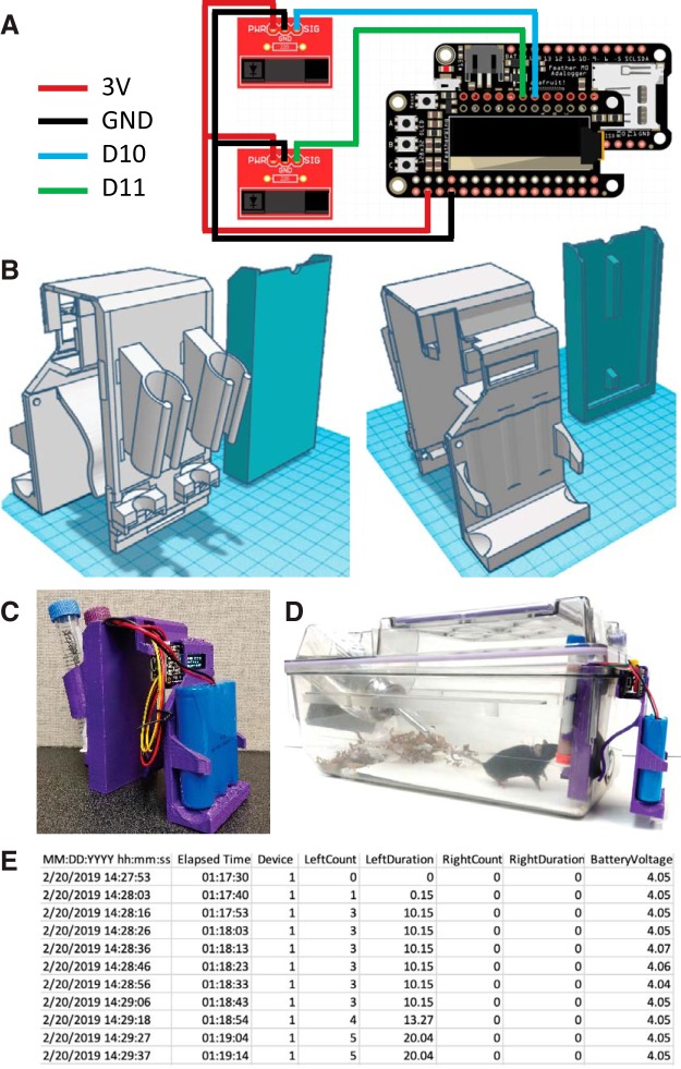
Figure 1.
Construction and implementation of a home-cage drinking monitor. A, Circuit wiring diagram of electronic components; 3 V power is supplied to the photo-interrupters, which are connected to a ground pin. Each photo-interrupter is also attached to a digital output pin (shown as D9 and D10). B, 3D rendering of the 3D printed housing for the drinking monitor; views of the front tube assembly (left) and rear battery casing (right) are shown. C, D, Photo of the assembled device (C) and the assembled device operating in the home cage (D). E, Example data as written to the SD card.

