Abstract
The extreme flexibility of the octopus arm allows it to perform many different movements, yet octopuses reach toward a target in a stereotyped manner using a basic invariant motor structure: a bend traveling from the base of the arm toward the tip (Gutfreund et al., 1996a). To study the neuronal control of these movements, arm muscle activation [electromyogram (EMG)] was measured together with the kinematics of reaching movements. The traveling bend is associated with a propagating wave of muscle activation, with maximal muscle activation slightly preceding the traveling bend. Tonic activation was occasionally maintained afterward. Correlation of the EMG signals with the kinematic variables (velocities and accelerations) reveals that a significant part of the kinematic variability can be explained by the level of muscle activation. Furthermore, the EMG level measured during the initial stages of movement predicts the peak velocity attained toward the end of the reaching movement. These results suggest that feed-forward motor commands play an important role in the control of movement velocity and that simple adjustment of the excitation levels at the initial stages of the movement can set the velocity profile of the whole movement. A simple model of octopus arm extension is proposed in which the driving force is set initially and is then decreased in proportion to arm diameter at the bend. The model qualitatively reproduces the typical velocity profiles of octopus reaching movements, suggesting a simple control mechanism for bend propagation in the octopus arm.
Keywords: movement control, muscular-hydrostats, reaching movements, EMG, muscle activation, motor programs, octopus, cephalopods
The octopus arm, like other cephalopod tentacles, vertebrate tongues, and the elephant trunk, lacks either external or internal skeletal elements. In contrast to articulated appendages, the muscles in these structures not only create the movements but also supply the skeletal support (Kier, 1982). Kier and Smith (1985) termed these structures muscular-hydrostats because they are composed mainly of incompressible muscle tissue. They suggested that the production of movement and force in these muscular-hydrostats is dictated by this constant volume constraint. Their ideas have served as general principles for studying muscular-hydrostats biomechanics (Wilson et al., 1991; Van Leeuwen and Kier, 1997).
The octopus arm is an especially interesting muscular-hydrostat because it combines extreme flexibility (an octopus arm can bend at any point in any direction and can elongate, shorten, and twist) with the ability to execute various sophisticated tasks such as catching a target, building a shelter, manipulating objects (Wells and Wells, 1957; Wells, 1978), and opening a jar (Fiorito et al., 1990).
This ease with which the octopus moves its arms is a delight to the ordinary observer but imposes a serious theoretical problem to robotocists and those studying arm movements. The difficulties lie in the so-called “inverse kinematics” and “inverse dynamics” problems—the problems of transforming the task into the appropriate kinematic variables describing the arm movement (the “inverse kinematic problem”) and into the appropriate muscle activation pattern (the “inverse dynamic problem”) (Bizzi et al., 1991;Flanders and Hermann, 1992). The complexity of these transformations is attributable partly to the excess degrees of freedom of the limb compared with the number of degrees of freedom of the end effector or those available at the task level (Hollerbach, 1990; Bizzi, 1993;Gielen, 1993). In flexible structures in which the number of degrees of freedom is practically infinite, the inverse problems are much more profound.
In a previous study (Gutfreund et al., 1996a), we showed that the movement of an octopus arm reaching toward a fixed target is performed in a very stereotyped way by wave-like propagation of a bend from the base of the arm to its tip. This work has resulted in the discovery of certain invariants in this motion, of which the most robust is the velocity profile of the propagating bend and its confinement to one plane. We suggested that the robust use of consistent movement patterns helps overcome the kinematic redundancy problem embedded in the flexibility of the octopus arm and thus greatly simplifies motor control.
Here, we examine the inverse dynamics problem by investigating whether there are invariances and simple scaling in the muscle activation patterns that generate these consistent movement patterns. We show that the propagating bend is accompanied by a wave of muscle activation whose level correlates with the velocity profiles of the bend movements. Furthermore, we demonstrate a significant correlation between the electrical activity in the muscles during the initial stages of the motion with the velocity reached toward the end of the movement. Our results demonstrate a relatively simple cause and effect relationship between muscle activation and the movement kinematics (a propagating bend). This may be the means by which the inverse dynamic problem in flexible arms is simplified.
Part of this work has been presented previously in abstract form (Gutfreund et al., 1996b).
MATERIALS AND METHODS
Experimental animals and materials. Specimens ofOctopus vulgaris were collected in the Bay of Naples and the experiments were performed in the Zoological Station, Naples. The weight of the animals studied ranged from 200 to 500 gm. We used animals that were satisfactorily adapted to captivity and were accustomed to reach toward a target to obtain food. The anesthesia used for implanting electrodes was a mixture of 1.5% ethanol in seawater. Experiments were performed in a 75-cm-long × 35-cm-wide × 40-cm-deep aquarium with running seawater. After the experiment the animals were again anesthetized, and in several cases, the arm carrying the electrode was amputated and fixed in 4% formalin in seawater to determine electrode location.
Electromyogram (EMG) recordings. Anesthetized animals were placed on a dissecting platform and covered with tissue paper soaked with a mixture of 1.5% ethanol in seawater. Electrodes were then implanted in the musculature of the arm under a dissecting microscope.
Electrodes consisted of a Teflon-coated stainless steel wire (0.13 mm coated diameter; A-M Systems, Inc.) tied to a plastic bead (2 mm diameter) leaving two free ends: a long “proximal” end (∼50 cm long) and a short “distal” end. The proximal end was later connected to the input channel of the amplifier. Approximately 1 mm of the insulation was removed from the wire, distal to the bead, at a distance matching half the width of the arm (in most cases we chose to implant the electrode where the arm diameter was ∼1 cm).
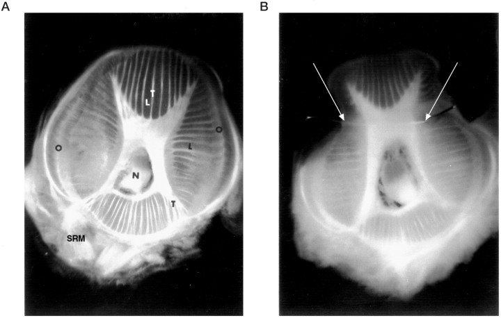
To implant the electrode in the arm, a fine syringe needle (25 ga × 16 mm) was first inserted across the arm through the musculature. The distal end of the stainless steel wire was then threaded through the tip of the needle, and the needle was pulled out, leaving the wire in the muscle (Fig.1B). A second bead was then tied and glued to the other side. These beads served both to anchor the electrode in place and to flag its location. Finally, the distal end of the wire was cut as close as possible to the bead, and the tip was immersed in Histoacryl glue. Because there are no apparent landmarks on the octopus skin, it is difficult to position the electrodes at the same locations in different experiments. Thus, some variability in the electrode location cannot be avoided (see Fig. 5,insets). The electrodes were inserted at a location roughly dorsal to the axial nerve cord (Fig. 1B) without aiming at a particular muscle. The dorsal position was chosen to reduce the possibility of recordings from the nerve cord or the sucking rings musculature. More common techniques for implanting electrodes, such as gluing the wire to the octopus skin with tissue adhesive or using a rigid needle as an electrode (Kier et al., 1989), were found unreliable because the octopuses easily succeeded in pulling out such electrodes.
Fig. 1.
Transverse section through the octopus arm.A, The intrinsic musculature of the arm is an array of densely packed muscle fibers organized in three main directions: longitudinal fibers (L), transverse fibers (T), and oblique fibers (O). N, Axial nerve cord in the center of the arm: SRM, muscles of the sucking rings on the ventral side. Dorsal side is up. B, Transverse section at the level of an EMG electrode showing the stainless steel wire position (white arrows) inside the intrinsic muscle.
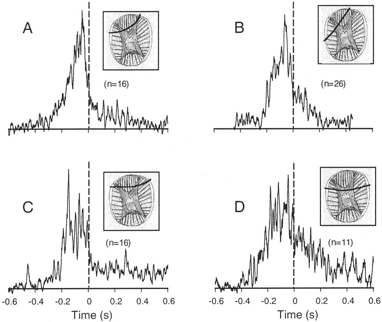
Fig. 5.
Average EMG profiles measured during bend propagation. The smoothed rectified EMG profiles from all reaching movements in the same animal were aligned at the bend time and averaged. A–D, Averages from different animals. Thevertical dashed line marks the bend time. The scheme in the insets shows the location of the electrode wire (bold line) in the transverse section of the arm.
The electrodes were wired to a low-level differential AC amplifier (model DP-301, Warner Instrument Corp.), and muscle activity was recorded differentially between the electrode and a stainless steel wire immersed in the water near the octopus; the whole tank was grounded and connected to the amplifier ground. The signal was amplified (10,000×), bandpass-filtered (0.3–10 kHz), displayed on an oscilloscope, and recorded digitally on a videotape (Neurodata). For synchronization purposes, the signal was also recorded on one of the high-fidelity audio channels of the video recorder that we used to record the movements (see below).
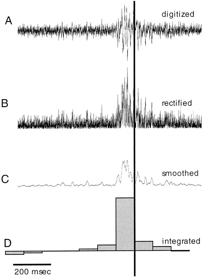
EMG records were preprocessed for further analysis in three steps. (1) For each reaching movement, a time section that included the entire movement was selected for subsequent analysis. Figure2 shows an example of the stages of this analysis. The signals were digitized at a rate of 5 kHz (Fig.2A) and rectified (Fig. 2B). (2) The rectified signals were smoothed using a running average of 10 msec duration, and the average baseline was set to zero (Fig.2C). (3) To quantify the level of activity, the smoothed signal was integrated. The integration time was divided into different time bins. In the example shown in Figure 2D, the signal was integrated over time bins of 100 msec.
Fig. 2.
Processing of the EMG signal. A, An EMG signal measured during a reaching movement. The time of the video frame during which the bend passed the electrode site (bend time) is indicated by the vertical line. The signal was rectified (B) and smoothed using a running average of a 10 msec duration (C). The smooth signal was integrated over time bins of 100 msec and displayed as the histogram inD.
Behavioral task and video recordings. After electrode installation, the anesthetized animals were placed in the experimental tank and allowed to recover for a few minutes. A target was inserted in the water and moved slightly to attract the octopus’ attention. The target was either a plastic sphere (∼2 cm diameter) connected to a transparent rod or a live crab tied to a string. It was placed so that an imaginary line connecting the animal with the target was approximately perpendicular to the video camera to ensure that a significant component of the reaching movement was in the plane of the video image. Every few trials, a small piece of fish meat was attached to the target as a positive reinforcement.
The reaching movements were recorded by two video cameras, one viewing the aquarium from above (upper camera) and the other from the front of the aquarium (side camera). The PAL S-VHS system allowed a temporal resolution of 20 msec between adjacent images (video fields). The images from the upper camera were used to verify that the main part of the movement was in the plane of the side camera image. We allowed for deviations of up to 45° from this plane, which introduced a maximal error of 30% in the estimation of velocity. The way we presented the target (as above) reduced the number of reaching movements not satisfying this criterion to <5%. A third camera monitored the oscilloscope screen, and a video mixer combined its image with the side camera, allowing a simultaneous display of both movement and EMG signal (see Fig. 4A–C).
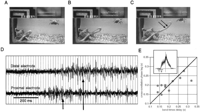
Fig. 4.
EMG recordings in a freely moving octopus.A–C, Three video frames showing an octopus reaching toward a target (a crab in the top right-hand corner of the picture); two electrodes (arrows inC) are implanted in its arm. The top partof each frame shows the electrical activity simultaneously recorded by the electrodes. D, The electrical activity measured by the proximal and distal electrodes during the movement shown inA–C. The vertical grid lines mark the opening of the video camera shutter, which gives the temporal resolution of the video recordings (20 msec between adjacent video fields). The arrows in D indicate the times at which the bend in the arm passed the recording sites: first the proximal electrode and then the distal electrode. E, The cross-correlation phase lag of EMG signals of 11 reaching movements plotted versus the delay for the bend to reach the distal electrode (bend-times delay). The bold line marks the equal time line. The inset shows the cross-correlation function between the rectified nonsmoothed signals in D over a span of 1.8 sec. The intersection of the axes is at zero phase lag.
Kinematic analysis. Successive video frames of reaching movements filmed by the side camera were digitized and displayed on a Silicon Graphics workstation. As described in the introductory remarks, all reaching movements were generated by a single bend, propagating along the arm. The midpoint of this bend and one of the eyes were marked manually with the mouse cursor, and the coordinates of these two points were saved for later kinematic analysis.
For each reaching movement, we define the bend time as the time at which the propagating bend reached the electrode. It was determined by searching frame by frame for the image at which the midpoint of the bend was localized at the plastic bead marking the electrode. The upper camera was used to achieve a more precise estimation. This bend time was used as a reference point for relating the EMG signal to the movements.
The kinematic features of arm extension were basically characterized by the procedure described previously (Gutfreund et al., 1996a). Briefly, the movement of the arm related to the body was obtained by vectorially subtracting the measured movement of the eye from the bend-point movement. The tangential velocity of the bend, i.e., its velocity in the direction of the movement in a coordinate system fixed to the animal eye, was calculated from the relative movement data. We first smoothed the data by fitting a fifth order polynomial to the projection of the points on the x-axis and y-axis as a function of time (one polynomial for x(t) and one for y(t)) using a least square method. The tangential velocity was calculated from the derivatives of the smoothedx(t), y(t) coordinates, i.e., v = . We measured the projected trajectories in two dimensions, in contrast to our previous study in which we measured actual three-dimensional trajectories. However, this simplification can be used without losing important information, for we have shown that the movement path is confined to a single plane (Gutfreund et al., 1996a), and as mentioned above, we limited our measurements to movements performed more or less within the image plane.
Movement artifacts. To inspect for movement artifacts in the electrical recording that could have resulted from the motion of the electrodes and not from muscle excitation, we recorded from electrodes implanted in amputated arms that were forced to move in the aquarium. In some of the experiments, the arm with the electrode was cut and left for 1 hr so that all arm reflexes ceased. Whip-like movements were then generated by moving the base of the arm. The video images and the electrical recordings from the amputated arms were analyzed in the same way as the natural movements. Movement artifacts were generated at electrode velocities higher than 100 cm/sec. No significant artifacts were found within the range of velocities of natural octopus movement (0–50 cm/sec).
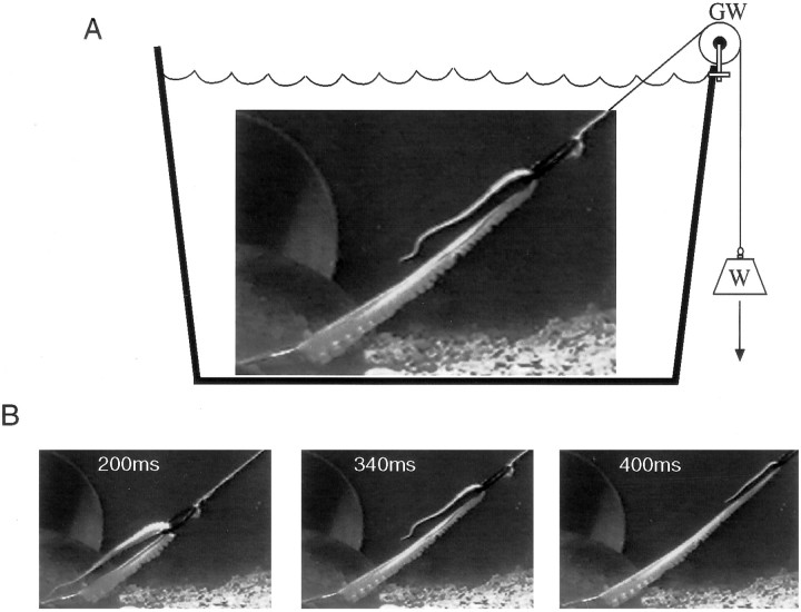
Estimation of drag force. A simple mathematical model was used to gain more insight into the dynamics of octopus arm extension (see ). When studying dynamics of motion in water, it is important to estimate the drag forces that arise from the interaction of the body with the water. These can be analyzed theoretically by applying Navier-Stokes theory, but this requires complex modeling of the body and fluid dynamics (Williams et al., 1995). We therefore chose to estimate these forces empirically. An arm was amputated from an anesthetized octopus weighing ∼400 gm. The length, the diameter at different locations along the arm, and the weight of the arm were measured. The base of the arm was anchored to a stationary platform and the arm was inserted through a plastic ring weighing ∼1 gm and connected to a nylon line (Fig.3A). The other end of the line was connected to a weight through a low-weight groove wheel (Fig.3A, W, GW). Pseudo-reaching movements were generated by letting the weight fall and thus pull the ring along the arm. This resulted in propagation along the arm of a bend resembling the typical extension movement (compare Figs. 3B,4A–C). The tangential velocities of the propagating bend were measured at different pulling weights using the same procedure described in the kinematic analysis.
Fig. 3.
Schematic illustration of the apparatus used to estimate the drag forces. A, The base of an amputated arm was attached to the bottom of the aquarium. The arm was inserted through a plastic ring connected to a weight (W) through a groove wheel (GW). Letting the weight fall caused the ring to slide along the arm, thus inducing the bend in the arm to propagate forward similarly to a natural extension movement (B).
The pulling force and the physical parameters of the arm were used to simulate the movement with the model described in the . The drag force was estimated by fitting the simulated velocity profile to the velocity profile generated in the amputated arm (see Fig.10A).
Fig. 10.
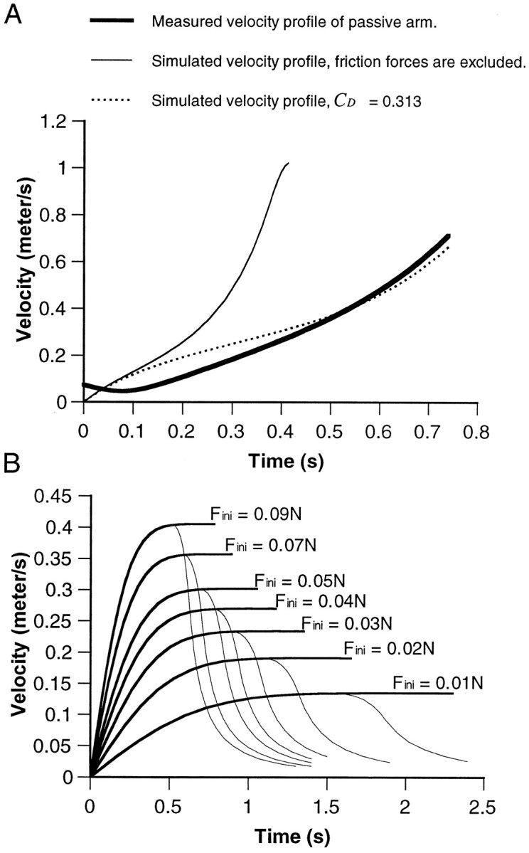
Velocity profiles of simulated movements.A, The thick solid line gives the tangential velocity of the bend point generated in a passive arm by pulling with a weight of 11 gm (see Materials and Methods). This velocity profile is compared with the simulated velocity profiles of the arm pulled by the fixed gravity force. The thin solid line represents the solution where the drag forces are excluded. The dashed line gives the solution where the drag coefficient (CD) is set to 0.313. This value of CD gives the best fit (minimal mean square difference) to the velocity profile measured from the passive arm. This CD value was used to simulate the reaching movements where the pulling forceFmuscle was proportional to the cross-section area of the arm at the bend point. The results are shown in B. The thick lines give the velocity profiles obtained for different initial force (Fini). The thin linesbranching from each curve are the velocity profiles whereFmuscle is set to zero when the bend point has traveled >70% of the length of the arm.
RESULTS
Five of 30 experiments, each in a different animal, were successful. A successful experiment was one in which we collected at least 10 typical undisturbed reaching movements of the arm carrying the electrodes. In the unsuccessful experiments, the animals were probably disturbed by the electrodes and therefore did not react to the target at all or used only the arms without the electrodes. The five successful experiments yielded 111 reaching movements. Of these, 85 movements were smooth and uninterrupted and served as the data pool for the present study.
In all experiments, the electrodes were implanted in the dorsal part of the intrinsic musculature of the arm. This is the main musculature of the arm (excluding the sucker and the subdermal muscles), and it is responsible for movement generation. The intrinsic musculature is composed of closely spaced, alternate layers of longitudinal and transverse muscle fibers and of two peripheral layers of helical muscles (oblique muscles) (Fig. 1A). All of these muscle fibers are innervated by axons originating from motor neurons in the axial nerve-cord (Young, 1965; Graziadei, 1971; Matzner et al., 1996). The basic morphology of this cross section is conserved along the arm even as it tapers. This unique muscle organization imposes difficulties in distinguishing between the activation of specific muscle groups (Gosline et al., 1983; Kier et al., 1989). The activity thus measured presumably includes currents carried by both longitudinal and transverse muscles and may also include oblique muscle fibers. We also cannot exclude the possibility that neuronal activity was included in the electrical signal.
Qualitative observation
A reaching movement involves a bend propagating along the arm (Fig. 4). This movement can be divided into three stages, as shown in Figure 4A–C. (1) During the period before the bend in the arm reaches the recording sites, no electrical activity is recorded (Fig. 4A). (2) The bend proceeds through the recording sites (Fig. 4B), and a burst of electrical events is recorded. (3) After the bend propagates farther away (Fig. 4C), activity is maintained, but at a lower frequency. The electrical activity recorded by the proximal and distal electrodes over the entire course of movement is displayed in Figure4D. The arrows in Figure 4Dindicate the frames at which the bend in the arm reached the electrode sites (bend times). Electrical activity was recorded first at the proximal electrode and was followed by activity in the distal electrode. The ∼160 msec delay between the onsets of activity at each electrode corresponds to the delay between the bend times (eight video fields). Alternatively, the phase lag between the two EMG waveforms can be estimated by measuring the lag for the peak in the cross-correlation function. The rectified nonsmoothed signals measured in the distal and proximal electrodes were cross-correlated. The cross-correlation plot of the signals in Figure 4D is shown in the inset in Figure 4E; it demonstrates a phase lag of 140 msec between the two signals. The cross-correlation phase lags, measured from different reaching movements, agree with the delays between the bend times, as is evident from Figure 4E. This suggests that the wave of muscle activity accompanies the bend propagation at a similar speed. The sustained after-activity (Fig.4C) may reflect active stiffening of the proximal part of the arm that is necessary to keep this part straight. Note that this activity is not necessarily associated with the movement of the electrode. For example, in Figure 4A there is no activity while the electrodes are moving with the arm, whereas in Figure 4C, clear activity is recorded in both electrodes while the electrodes are relatively immobile.
To allow averaging of different movements, these must first be aligned with respect to a common time axis. The usual procedure of aligning movement or activity onset is not possible in octopus reaching movements because onsets and offsets are not clearly identifiable. We therefore aligned all movements to the bend time; this provides a common time axis and allows averaging and comparison of different movements.
The smoothed and averaged EMG profiles of movements in four animals are shown in Figure 5. The averages included movements at different speeds. However, because the EMG waveform width is not correlated with the speed of movement (see below), pooling movements of different speeds to obtain the average waveform is justified. On average, muscle activity in all experiments began 300–200 msec before the bend reached the recording site (dashed line), peaked between 100 and 50 msec before the bend time, and then decreased to a lower level. This general EMG waveform displays a high degree of similarity in the different animals despite the variability in the precise locations of the electrodes (Fig. 5,insets) (see Materials and Methods). On the other hand, the activity observed after the bend time seemed more variable; e.g., it was more distinct in Figure 5C,D than in Figure5A,B.
Relationship between the EMG levels measured from two electrodes
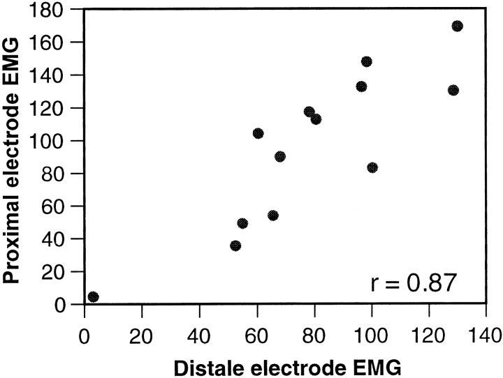
The simultaneous measurement of activity at different locations along the arm allowed us to test whether the activity propagated as a constant amplitude wave. Two EMG electrodes were implanted at a distance of 2 cm apart along the longitudinal axis of the arm. For each movement, the EMG signal in both electrodes was integrated over a period of 300 msec around its bend time. Figure6 shows a plot of the proximal electrode integrated EMG versus the distal electrode integrated EMG from 13 reaching movements. The activity measured in the two electrodes was positively correlated, as indicated by the linear coefficient of correlation (r = 0.87; p < 0.01), suggesting that the EMG wave is not modulated during propagation. A wave, which is initiated as a strong wave, will continue to travel as such and vice versa. This could not be tested further by using a greater separation because the octopuses did not tolerate electrodes implanted farther toward the tip. Nevertheless, the results in the next section provide additional support for this suggestion.
Fig. 6.
Correlation between the EMG signal recorded from proximal and distal electrodes. Each EMG measured was integrated over a period of 300 msec around the bend time. The integrated EMG measured at the proximal electrode is plotted against the integrated EMG measured at the distal electrode. The two electrodes were implanted 2 cm apart along the longitudinal axis of the arm.
Relationship between EMG signal and kinematic variables
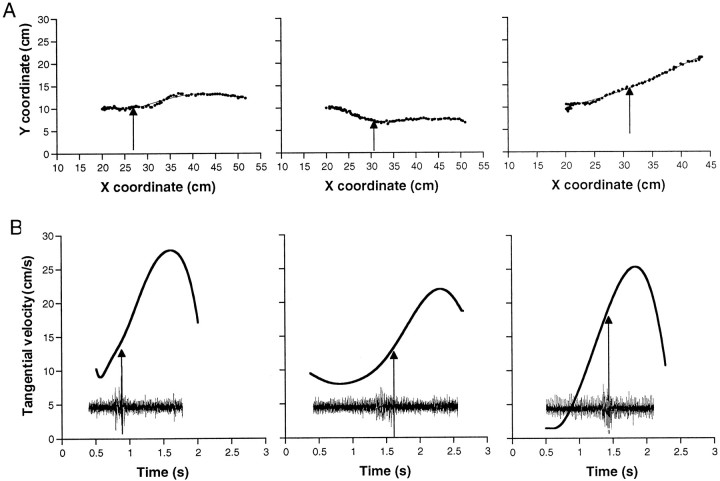
Both the path of the bend point in the plane of image and its tangential velocity were measured and calculated from 85 reaching movements (see Materials and Methods). The kinematic features observed in the present study (Fig. 7) agreed with the previous kinematic study of unrestrained octopus reaching movements (Gutfreund et al., 1996a), suggesting that the application of anesthesia and electrode implantation did not effect the natural kinematics of these movements. Figure 7A shows the bend-point path, relative to the animal body, of three different movements. The bend point moves in a relatively simple path that is slightly curved or nearly a straight line. The corresponding velocity profiles (the tangential velocity of the bend point as a function of time) together with the corresponding EMG recordings are shown in Figure 7B. It should be noted that a bend is a dynamic structure that can evolve or disappear during the movement of the arm, and thus, as can be seen from this figure, the velocity may start and end at values other than zero. Although the range of velocities in these movements varied, they tend to follow a characteristic velocity profile starting with an initial phase of low velocity followed by a phase in which the velocity increased to a peak. The bend times (marked by the arrows) occurred at different times in the accelerating phase before the maximum velocity was reached.
Fig. 7.
Bend-point trajectories during reaching movements.A, Bend-point path measured in different trials. Thedots are the measured positions, and thelines are the fitted fifth-order polynomial. Thearrows mark the point measured from the video frame in which the bend passed the electrode. The movement direction is from left to right. B, The bend-point tangential velocity plotted against time, calculated from the smooth movement path during the trials in A. The arrows mark the bend time. The insets show the corresponding EMG recording plotted on the same time axis as the velocity profiles.
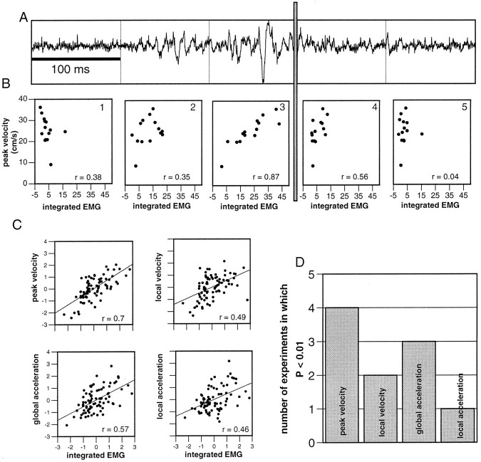
To assess the relationship between muscle activity and movement in a quantitative manner, the linear coefficient of correlation (r) was calculated between the integrated EMG and the following four kinematic variables: (1) peak velocity, the maximum velocity attained by the bend; (2) local velocity, the velocity measured at the bend time; (3) local acceleration, the acceleration at the bend time obtained from the numerical derivative of the velocity profile; and (4) global acceleration, the slope of the increasing phase of the velocity profile measured as the two-points difference (v2 −v1/t2 −t1) between 10% above the minimum velocity to 10% below the maximal velocity. This variable was used to estimate the acceleration during the main part of the extension. The results in Figure 8A,Bwere obtained from one experiment in which the octopus performed 14 reaching movements. Each scatter plot in Figure 8Bshows the peak velocity versus the integrated EMG over a time bin of 100 msec. The time bins are assigned in relation to the bend time (vertical gray bar), starting 300 msec before the bend time (plot 1) and ending 200 msec after the bend time (plot 5). One trace of the raw data, aligned in this way, is shown in Figure 8A. Highest EMG values were measured in the 100 msec preceding the bend time (compareplot 3 with plots 1, 2, 4, and 5). As shown also in Figure 5, this time bin includes the major part of the EMG signal. The integrated activity in this time window displayed a large variability related to that of the peak velocity. Movements with higher EMG values tended to higher peak velocities (r = 0.87) (Fig. 8B, plot 3). EMG values drop after the bend time (Fig. 8B, plots 4, 5), and the correlation is lost. It is evident that the signal measured during the 100 msec before the bend time correlates most significantly with the peak velocity.
Fig. 8.
Correlation between EMG levels and kinematic variables. A, The potential recorded during a representative reaching movement. The trace is partitioned into bins of 100 msec, with the reference time for the division being the bend time (vertical gray bar in A andB). B, Correlations between peak velocity of the movement and the integrated EMG during the corresponding time bin (bins as in A). The coefficient of correlation (r) is indicated in each graph. C, Standardized integrated EMGs over the 100 msec before the bend time plotted against each of the kinematic variables: peak velocity, local velocity (measured at the bend time), global acceleration (see Results), and local acceleration. Data were pooled from all five experiments. The linear coefficient of correlation (r) is indicated in each graph. Anf test examined the statistical significance of the correlation. The histogram in D shows the number of experiments in which p < 0.01 for each kinematic variable.
The remaining three kinematic variables (local velocity, local acceleration, and global acceleration) behaved similarly. Ther values calculated from the 100 msec before the bend time were larger than the r values calculated from other time bins. The scatter plots in Figure 8C show the different kinematic variables versus the integrated EMGs during the 100 msec proceeding the bend time. To pool data from different experiments, we standardized the kinematic variables and the EMG by subtracting the mean value and dividing by the SD. The variability of all the examined kinematic variables can be explained, at least partly, by the variability of the integrated EMG. However, the level of significance among the different variables is clearly different.
An f test was applied to each experiment to further check the significance of the correlation. The histogram in Figure8D shows in how many of the five experiments thep value was <0.01. Peak velocity was more robustly correlated with the EMG signal (four of five experiments) than local velocity (two of five experiments) and global acceleration, which score better (three of five experiments) than local acceleration (one of five experiments). These findings demonstrate that the EMG levels are clearly related to the global kinematic variables (peak velocity and global acceleration), which are not recorded at the same time as the EMG signal. The maximum velocity, for instance, occurs well after the signal is measured. The peak velocity was generally reached when the bend had traveled farther along the arm (Fig. 7B): on average, 550 ± 320 msec (n = 62) after the bend time. This indicates that muscle activity measured at the initial stages of the movement can predict the velocity that will occur later on. To verify this, we selected the movements in which the delay between the bend time and the time of peak velocity was longer then half a second. The coefficient of variance measured in this case (r = 0.74; n = 33) is very similar to the coefficient of variance measured for all the movements (Fig.8C) (r = 0.7), confirming that the correlation is maintained in the group of movements in which the peak occurred farther toward the end of the movement.
Although the amplitude of the EMG signal is correlated with the peak velocity, the width of the EMG burst was found to be independent of the movement speed. In Figure 9A, three smoothed EMG signals are aligned at the peak. The EMG signals show differences in the amplitude correlating with the velocity profiles, but the width of the signal does not vary. The corresponding velocity profiles are shown in Figure 9B. These vary in both peak velocity and duration. The delay between the peak of the EMG signal and the bend time (Fig. 9A,B, arrows) was not significantly correlated with the velocity (both peak and local).
Fig. 9.
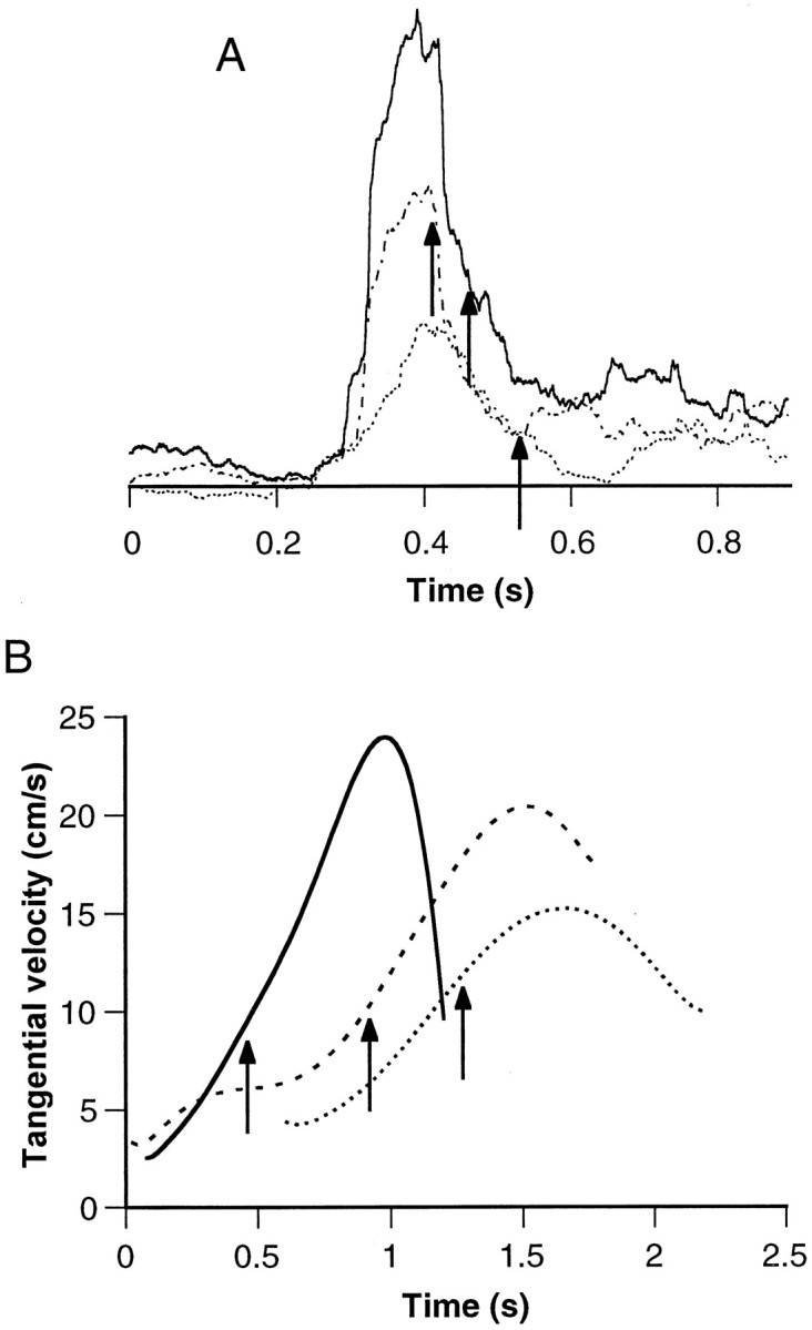
EMG amplitude, but not duration, is scaled according to speed of bend propagation. A, Three rectified and smoothed EMG signals (smoothed with a running average of a 100 msec duration) aligned at the peak of the signal.Arrows indicate when the bend point reached electrode location (bend time). B, Bend-point tangential velocity profiles of the corresponding movements, as indicated by line style.Arrows mark the bend times. Note the correspondence of the EMG amplitudes with the peak velocities.
DISCUSSION
We present here for the first time recordings of arm EMGs in freely behaving octopuses. The waveforms of muscle activity associated with octopus reaching movement were measured and quantified. The reaching movements, as is typical in octopus arm extension, are generated by a bend propagating along the arm. Our results show that there is a relatively simple relationship between the EMG pattern and the movement, with the amplitude of muscle activation levels generally corresponding to the velocity profile of the extension.
Mechanism of propagation
A propagating bend can be generated in flexible structures, either by a passive whip-like action without muscle activation during the propagation itself or by an active mechanism involving muscle contraction accompanying the propagation (Hines and Blum, 1978). A passive mechanism would require an initial contraction of muscles at the base of the arm to provide the necessary energy to produce a curvature wave. However, we have shown here that bend propagation in the octopus arm is accompanied by a propagating wave of muscle activity, indicating an active process. Such a mechanism is better suited for direct control of the bend movement.
The most obvious feature in the average EMG waveform is that most of the activity precedes the time at which the propagating bend reached the electrode (bend time) in a rather constant delay (Fig. 5). This delay may be attributable only to excitation–contraction delays, and if so, the main contraction occurs right at the bend. We do not yet know the exact excitation–contraction delay in these muscles. However, in fish muscles this delay is of the order of tens of milliseconds (Wardle, 1975), which is comparable to the delay observed here between the EMG and the bend time. It should be mentioned, however, that in the dynamic situation such as flexible arm extension the point of maximal activity need not necessarily coincide with the point of maximal curvature. For example, in several fish species the rostrocaudal EMG wave that gives rise to the swimming movements travels faster than the curvature wave of the body (Grillner and Kashin, 1976; Wardle et al., 1995), with the result that the EMG burst precedes the curvature wave at the recording site. This phenomenon has been attributed to the complex physical interactions between the animal’s body and the water (Blight, 1977; Bowtell and Williams, 1994).
There are two hypotheses for the muscle activation strategies that could produce this type of bend propagation in muscular-hydrostats. The first is that the bend is formed by coordinated muscle contractions that produce the bend locally by appropriately activating the longitudinal and the transverse muscles in the appropriate pattern.Kier and Smith (1985) suggested that bending takes place when the longitudinal muscles on one side of the arm contract simultaneously with activation of the transverse muscles that resist longitudinal compression (attributable to the constant volume constraint). This pattern can be propagated down the arm, and this in turn will cause the bend to propagate. The second hypothesis is that a stiffening front straightens the bend and propels it toward the tip of the arm (a mechanism that resembles certain blow-up toys). Kier and Smith (1985)pointed out how the longitudinal and transverse muscle groups can function as antagonistic muscles. Stiffening would then occur when both muscle groups are equally activated. This is an attractive mechanism for controlling movement because complex temporal and spatial coordination is not required, and hence motor control is simplified. The fact that the average time course of the EMG waveform was similar in all experiments, regardless of the electrode’s precise location (Fig. 5), may result from a similar pattern being applied simultaneously to all the muscle groups. This favors the notion of a stiffening wave. The workability of this hypothesis has been demonstrated in a dynamic model of an octopus arm (Aharonov et al., 1997).
A wave of muscle activation propagating along the arm may account for the propagation of a bend down the arm, but it does not by itself provide a specification of the direction of movement in space. In our previous kinematic study we showed that octopuses reach to targets by propagating a bend in the radial direction from the center outward. It is hypothesized there that the directional control is achieved by adjusting the two degrees of freedom at the base of the arm (yaw and pitch), at the beginning of the movement. Therefore, muscle activities in the octopus involved in directional control differ, both in time and location, from the muscle activities that produce the extension. This unique separation is in contrast to human reaching movements in which the same muscles participate in both direction and velocity control (Flanders, 1991).
The control of movement by modulating the stiffness of the limb, as may be the case in the octopus arm, may provide an attractive approach in the field of robotics. Recently, some attention has been paid to the novel development of highly flexible robot manipulators (Horgan, 1986;Wilson and Mahajan, 1989; Davies, 1991). These are manipulators composed of pneumatic tubes to which application of pressure results in the generation of a bending moment, depending on the internal pressure and structure. In this way, changes in internal pressure are transformed into movement. These manipulators are partly based on studies on muscular-hydrostats, such as the elephant trunk and squid tentacles (Wilson, 1984; Wilson et al., 1991). An understanding of the generation and control of octopus arm movements may similarly assist the engineer in designing and controlling such flexible robots.
Control of the propagation velocity
We suggested previously that an important control variable in the octopus reaching movement is the bend position in space and time (Gutfreund et al., 1996a). Here we examined the control of the velocity of bend propagation. The velocity of movement is of obvious importance for the ability to catch prey and is therefore probably under direct control of the nervous system. Although the general form of the velocity profile is relatively invariable (Figs. 7B,9B) (Gutfreund et al., 1996a), the velocity itself varies among the different movements. Discovery of what features in the EMG can account for these variations may provide insight into velocity control. This approach is commonly used for studying movement control in humans (Gottlieb et al., 1989; Flanders and Hermann, 1992). Despite the clear biomechanical differences between muscular-hydrostats and articulated arms, there should be a common principle: namely, that covariation between muscle activity and kinematic parameters usually points to a causal relationship in the direction from muscle to movement.
Our results demonstrate a significant correlation between the integrated EMG activity before the bend passed the recording site with movement velocity and acceleration. This suggests that it is the level of excitation of the muscles that regulates the velocity profile of the movement, with higher excitation levels resulting in higher propagation velocities. The integrated EMG is better correlated with the global kinematic variables (peak velocity and global acceleration) than with the local velocity and acceleration measured at the time of the EMG burst. This suggests that in reaching movements, the level of muscle excitation is related to the general features of the movements and not to a point-to-point control of velocity. However, we cannot completely exclude the possibility that the difference in the levels of correlation between the kinematic variables is attributable to the accuracy at which we can estimate these variables. For example, the acceleration is the second derivative of the measured noisy bend-point positions and therefore is expected to be less accurate. Furthermore, to measure local variables it is required to detect the time at which the bend point reached the recording site. This detection, by itself, has an error embedded in it. Therefore, the error in measuring local variables is expected to be larger than the global variables whose values are independent of electrode location.
An important finding is that the EMG signal significantly correlates with the velocity that is measured farther in time. This means that the EMG activity at the initial stages of movement can predict the velocity attained toward the end of the movement. The ability to predict indicates a strong feed-forward component, and this leads to the idea that a feed-forward motor program plays a major role in the control of movement.
One issue, however, still remains unclear. How is the propagation of muscle activation regulated? It can be determined by the nervous system in a pure feed-forward mechanism or it can be synchronized with the curvature wave by means of local feedback loops that sense the bend in the arm and adjust the propagating neuronal wave accordingly. Indeed, various local reflexes involving chemical, touch, and muscle sensation have been reported in the octopus arm (Wells and Wells, 1957; Rowell, 1966; Altman, 1971). Thus, it is most reasonable to assume that the movement of the arm is the outcome of both preplanned feed-forward central commands and interactions with the environment through the local sensorimotor feedback loops.
A simple mathematical model for reaching by the octopus arm
A common theme in the study of movement control is to what extent the mechanical properties of the arm and the interacting forces contribute to the kinematics (Krylow and Rymer, 1997). The simple stereotypical muscle activation pattern observed in our analysis raises the possibility that biomechanical factors and forces attributable to interaction with the surrounding water contribute significantly to the shape of the velocity profile. Indeed, in the following section we show, by means of a simplified mathematical model, that the interplay between the unique physical properties of the octopus arm and a simple motor command are at least sufficient to explain some of the observed findings.
The model arm is divided in a clear-cut manner into proximal and distal parts. The part proximal to the bend is stationary, whereas the distal part forms the moving mass whose movement is restricted to the direction along the arm; i.e., the model is one-dimensional. This highly simplified description is based on the fact that the arm extends so that the bend is highly curved and the distal part moves as if dragged behind the bend (Fig. 4). This feature of arm extension allows a clear separation between the distal and proximal regions.
We now assume that the net force generated by all the muscles can be lumped into a single force (Fmuscle) working in the direction of bend propagation. This force is assumed to be related simply to the level of activity recorded in the muscles (the EMG). Therefore, the choice of the muscle force used in the model is based on a monotonous propagation of an EMG wave. More specifically,Fmuscle starts at some initial force (Finit), which as the bend moves down the arm decreases proportionally to the cross-section area of the arm at the bend site (A(x)):
| Equation 1 |
where x is the position of the bend along the arm. This is justified because the arm is densely packed with muscle fibers; hence the cross-section area should represent the number of myofilaments available for force production.
Balancing the forces along the movement, according to Newton’s second law, gives the equation (see ):
| Equation 2 |
where x˙ is the velocity of the bend,ẍ is its acceleration, and m(x) is the mass of the distal part of the arm, and it depends on x according to Equation EA.6 (in the ), which considers the tapering of the arm. Fdrag is the drag force that resists the motion through the water. Equation 3 was taken as a simplified approximation for the drag forces. This notion is commonly used to describe drag forces in fish movements (Alexander, 1977; Dickinson, 1996):
| Equation 3 |
where ρ is the density of the fluid, and S is some surface area depending on the geometry of the body and its movement. Here we used the surface area of the distal part because this is a streamlined body that is expected to experience friction drags but relatively less pressure drag. CD is the dimensionless drag coefficient whose value depends on the shape of the body and on the Reynolds number in a nontrivial way (Jordan, 1992).
To obtain an estimation of the drag coefficient, we measured velocity profiles of passive (amputated) arms moving in seawater (see Materials and Methods). One such profile is given in Figure10A (bold line). In this case, the movement was generated by pulling the arm with a constant force of 11 gm. The thin line in Figure10A shows the simulated velocity profiles calculated according to Equation 2, with no drag forces (CDset to zero). The large difference between the two curves suggests that drag forces play a significant role in shaping the velocity profiles. The minimal root mean square difference between the two curves is obtained for CD = 0.313 (dashed curve). Despite the simplified representation of both drag forces and arm morphology, the simulated velocity profile (dashed curve) reproduces the general features of the measured velocity profile. This value of CD was therefore used in calculating the velocity profiles in the next step where we simulated octopus arm extensions.
Figure 10B shows a family of velocity profiles (bold lines), each calculated using a differentFinit. In all profiles, the velocity reaches a plateau of some maximal velocity. This velocity and the plateau are clearly correlated with the initial force.
The simulated velocity profiles reproduce some of the features of the actual reaching movements. Both measured and simulated profiles tend to follow a common shape and are characterized by a prominent phase of increasing velocity (compare Figs. 7B, 9B, and10B). The most obvious difference between reaching movements and the simulations is that the velocity profiles of the actual movements usually demonstrate a peak, in contrast to the plateau obtained in the model. The model can predict, therefore, only the accelerative phase of the movement. This may indicate that a different strategy is used during the terminal phase of the movement. More specifically, this phase may be shaped mainly by feedback, similarly to what was suggested in the final phase of human aiming movements (Rosenbaum, 1991). The decelerative phase could not be probed experimentally because the bend always passed the recording site during the accelerating phase. However, by setting the modelFmuscle to zero before reaching the tip, we simulated the possibility that the muscle activity in the natural arm extension is terminated before reaching the tip of the arm. The curves shown by the thin lines in Figure 10Bare velocity profiles calculated as were the bold curves, except that here Fmuscle was terminated forx > 70% of the arm length (the choice of the termination point is rather arbitrary). Indeed, this condition results in peaks in the velocity profiles. Changes in the activation level toward the end of the movement can therefore generate the observed behavior.
The model shows that the interplay between a simple internal force (Fmuscle) and the water forces that act on the moving arm, both constrained by the tapering structure of the arm, is sufficient to account for some of the main features of the experimentally observed velocity profiles of the reaching movements. The model also demonstrates that the level of the initial force can set the velocity of arm extension.
The model arm is represented as a cone of length l =26 cm, base radius r = 8.5 mm, and massmtotal = 25 gm, values obtained from an arm of an octopus weighing ∼400 gm. The variable x is the position of the bend, x˙ is its velocity, andẍ its acceleration. The parameter s ε [0,l] indicates the position along the arm, and λ(s) is the longitudinal mass density defined by:
| Equation EA.1 |
The momentum of the arm is given by:
| Equation EA.2 |
where V(s) is the velocity of the points:
| Equation EA.3 |
All the points proximal to the bend point (s <x) are assumed to be stationary. Note that the points distal to the bend point (s ≥ x) move at twice the velocity of the bend point because the distal points advance two units for each unit length traveled by the bend point. The sum of the force (F) is defined by the time derivative of the moment:
| Equation EA.4 |
Introducing V(s) from Equation EA.3 and λ(s) from Equation EA.1 to Equation EA.4 and solving the integral gives:
| Equation EA.5 |
where m(x) is the mass of the distal part of the arm determined by:
| Equation EA.6 |
Equation EA.5 can be evaluated to give:
| Equation EA.7 |
The derivative of Equation EA.6 with respect to xis:
| Equation EA.8 |
Inserting Equation EA.8 into Equation EA.7 and applying the chain rule:
gives:
| Equation EA.9 |
Rearranging Equation EA.9 to give x as the dependent variable gives:
| Equation EA.10 |
This ordinary differential equation is integrated numerically (initial conditions are x(0) = 0 and x˙ (0) = 0) by a fourth order Runga-Kutta method to obtain x andx˙.
Footnotes
This work was supported by the Office of Naval Research (N00014-94-1-0480), by the Israel Academy of Sciences and Humanities (190/95-1), and by United States–Israel Binational Science Foundation (95-00170). We Thank Yaakov Engel for his help in constructing the model, Dr. Orly Manor for statistical advice, Drs. Jenny Kien and Shay Gueron for advice and critical readings of this manuscript, Dr. Krishnaprasad for discussions and advice, and Drs. Idan Segev and Yosef Yarom for their guidance and help throughout this work.
Correspondence should be addressed to Yoram Gutfreund, Department of Neurobiology, Institute of Life Sciences, Hebrew University, Jerusalem 91904, Israel.
REFERENCES
- 1.Aharonov R, Engel Y, Hochner B, Flash T. A dynamical model of the octopus arm. Neurosci Lett Suppl. 1997;48:s1. [Google Scholar]
- 2.Alexander RM. Mechanics and energetics of animal locomotion. Chapman and Hall; London: 1977. [Google Scholar]
- 3.Altman JS. Control of accept reject reflexes in the octopus. Nature. 1971;229:204–206. doi: 10.1038/229204a0. [DOI] [PubMed] [Google Scholar]
- 4.Bizzi E. Intermediate representations in the formation of arm trajectories. Curr Opin Neurobiol. 1993;3:925–931. doi: 10.1016/0959-4388(93)90164-t. [DOI] [PubMed] [Google Scholar]
- 5.Bizzi E, Mussa-Ivaldi FA, Giszter S. Computations underlying the execution of movement: a biological perspective. Science. 1991;253:287–291. doi: 10.1126/science.1857964. [DOI] [PubMed] [Google Scholar]
- 6.Blight AR. The muscular control of vertebrate swimming movements. Biol Rev. 1977;52:181–218. [Google Scholar]
- 7.Bowtell G, Williams TL. Anguilliform body dynamics: a continuum model for the interaction between muscle activation and body curvature. J Math Biol. 1994;32:83–91. doi: 10.1007/BF00163025. [DOI] [PubMed] [Google Scholar]
- 8.Davies JBC. Elephant trunks: an unforgettable alternative to rigid mechanisms. Industrial Robot. 1991;18:29–30. [Google Scholar]
- 9.Dickinson MH. Unsteady mechanics of force generation in aquatic and aerial locomotion. Am Zool. 1996;36:537–554. [Google Scholar]
- 10.Fiorito G, Planta CV, Scotto P. Problem solving ability of Octopus vulgaris Lamarck. Behav Neural Biol. 1990;53:217–230. doi: 10.1016/0163-1047(90)90441-8. [DOI] [PubMed] [Google Scholar]
- 11.Flanders M. Temporal patterns of muscle activation for arm movements in three-dimensional space. J Neurosci. 1991;11:2680–2693. doi: 10.1523/JNEUROSCI.11-09-02680.1991. [DOI] [PMC free article] [PubMed] [Google Scholar]
- 12.Flanders M, Hermann U. Two components of muscle activation: scaling with the speed of arm movement. J Neurophysiol. 1992;67:931–943. doi: 10.1152/jn.1992.67.4.931. [DOI] [PubMed] [Google Scholar]
- 13.Gielen SC. Movement dynamics. Curr Opin Neurobiol. 1993;3:912–916. doi: 10.1016/0959-4388(93)90162-r. [DOI] [PubMed] [Google Scholar]
- 14.Gosline JM, Steeves JD, Harman AD, Demont ME. Patterns of circular and radial mantle muscle activity in respiration and jetting of the squid Loligo opalescens. J Exp Biol. 1983;104:97–109. [Google Scholar]
- 15.Gottlieb GL, Corcos DM, Agarwal GC. Organizing principles for single-joint movements I. A speed-insensitive strategy. J Neurophysiol. 1989;62:342–357. doi: 10.1152/jn.1989.62.2.342. [DOI] [PubMed] [Google Scholar]
- 16.Graziadei P. The nervous system of the arms. In: Young JZ, editor. The anatomy of the nervous system of Octopus vulgaris. Clarendon; Oxford: 1971. pp. 45–59. [Google Scholar]
- 17.Grillner S, Kashin S. On the generation and performance of swimming in fish. In: Herman RM, Grillner S, Stein PSG, Stuart DG, editors. Neural control of locomotion. Plenum; New York: 1976. pp. 181–201. [Google Scholar]
- 18.Gutfreund Y, Flash T, Yarom Y, Fiorito G, Segev I, Hochner B. Organization of octopus arm movements: a model system for studying the control of flexible arms. J Neurosci. 1996a;16:7297–7307. doi: 10.1523/JNEUROSCI.16-22-07297.1996. [DOI] [PMC free article] [PubMed] [Google Scholar]
- 19.Gutfreund Y, Fiorito G, Flash T, Segev I, Yarom Y, Hochner B. Characterization of arm muscle activity in a freely moving octopus (Octopus vulgaris). Soc Neurosci Abstr. 1996b;22:1638. [Google Scholar]
- 20.Hines M, Blum JJ. Bend propagation in flagella I. Derivation of equations of motion. Biophys J. 1978;23:41–57. doi: 10.1016/S0006-3495(78)85431-9. [DOI] [PMC free article] [PubMed] [Google Scholar]
- 21.Hollerbach JM. Fundamentals of motor behavior. In: Osherson DN, Kosslyn SM, Hollerbach JM, editors. Visual cognition and action. MIT; Cambridge, MA: 1990. pp. 151–182. [Google Scholar]
- 22.Horgan J (1986) Robotocists aim to ape nature. IEEE Spectrum February:66–71.
- 23.Jordan CE. A model of rapid-start swimming at intermediate Reynolds number: undulatory locomotion in the chaetognath Sagitta elegans. J Exp Biol. 1992;163:119–137. [Google Scholar]
- 24.Kier WM. The functional morphology of the musculature of squid (Loliginidae) arms and tentacles. J Morphol. 1982;172:179–192. doi: 10.1002/jmor.1051720205. [DOI] [PubMed] [Google Scholar]
- 25.Kier WM, Smith KK. Tongues, tentacles and trunks: the biomechanics of movement in muscular-hydrostats. Zool J Linn Soc. 1985;83:307–324. [Google Scholar]
- 26.Kier WM, Smith KK, Miyan JA. Electromyography of the fin musculature of the cuttlefish Sepia officinalis. J Exp Biol. 1989;143:17–31. doi: 10.1242/jeb.143.1.17. [DOI] [PubMed] [Google Scholar]
- 27.Krylow MA, Rymer WZ. Role of intrinsic muscle properties in producing smooth movements. IEEE Trans Biomed Eng. 1997;44:165–176. doi: 10.1109/10.552246. [DOI] [PubMed] [Google Scholar]
- 28.Matzner H, Gutfreund Y, Hochner B. Characterization of the neuromuscular system of the octopus arm. Isr J Med Sci. 1996;32:S42. [Google Scholar]
- 29.Rowell CHF. Activity of interneurons in the arm of octopus in response to tactile stimulation. J Exp Biol. 1966;44:589–605. doi: 10.1242/jeb.44.3.589. [DOI] [PubMed] [Google Scholar]
- 30.Rosenbaum DA. Human motor control. Academic; San Diego: 1991. [Google Scholar]
- 31.Van Leeuwen JL, Kier WM. Functional design of tentacles in squid: linking sarcomere ultrastructure to gross morphological dynamics. Philos Trans R Soc Lond B Biol Sci. 1997;352:551–571. [Google Scholar]
- 32.Wardle CS. Limit of fish swimming speed. Nature. 1975;255:727–729. doi: 10.1038/255725a0. [DOI] [PubMed] [Google Scholar]
- 33.Wardle CS, Videler JJ, Altringham JD. Tuning in to fish swimming waves: body form, swimming mode and muscle function. J Exp Biol. 1995;198:1629–1636. doi: 10.1242/jeb.198.8.1629. [DOI] [PubMed] [Google Scholar]
- 34.Well MJ. Octopus. Chapman and Hall; London: 1978. [Google Scholar]
- 35.Wells MJ, Wells J. The function of the brain of octopus in tactile discrimination. J Exp Biol. 1957;34:131–142. [Google Scholar]
- 36.Williams T, Bowtell G, Carling JC, Sigvardt KA, Curtin NA. Interactions between muscle activation, body curvature and the water in the swimming lamprey. Symp Soc Exp Biol. 1995;49:49–59. [PubMed] [Google Scholar]
- 37.Wilson JF. Robotics mechanics and animal morphology. In: Brady M, editor. Robotics and artificial intelligence. Springer; New York: 1984. pp. 419–443. [Google Scholar]
- 38.Wilson JF, Mahajan U. The Mechanics and positioning of highly flexible manipulator limbs. Trans ASME. 1989;111:232–237. [Google Scholar]
- 39.Wilson JF, Mahajan U, Wainwright SA, Croner LJ. A continuum model of elephant trunk. J Biomech Eng. 1991;113:79–85. doi: 10.1115/1.2894088. [DOI] [PubMed] [Google Scholar]
- 40.Young JZ. The diameters of the fibers of the peripheral nerves of octopus. Proc R Soc Lond B Biol Sci. 1965;162:47–79. [Google Scholar]


