Abstract
The ventral complex of the lateral lemniscus (VCLL, i.e., the ventral and intermediate nuclei) is composed of cells embedded in the fibers of the lateral lemniscus. These cells are involved in the processing of monaural information and receive input from the collaterals of the fibers ascending to the inferior colliculus. Whereas tonotopic organization is a feature of all other nuclei of the auditory system, this functional principle is debated in the VCLL. We have made focal injections of the tracer biotinylated dextran amine into different frequency band representations of the inferior colliculus in cat. Retrogradely labeled cells and terminal fibers (collaterals of efferent local axons and other ascending lemniscal fibers) were found in the ipsilateral VCLL. The spatial distribution of the labeling was analyzed using three-dimensional (3-D) reconstruction and computer graphical visualization techniques. A complex topographic organization was found. In all cases, labeled fibers and cells were distributed in multiple clusters throughout the dorsoventral extent of the VCLL. The shape, size, and location of the labeled clusters suggest an interdigitation of clusters assigned to different frequency-band representations. But an overall mediolateral distribution gradient was observed, with high frequencies represented medially and lower frequencies progressively more laterally.
We conclude that the clusters may represent discontinuous frequency-band compartments as a counterpart to the continuous laminar compartments in the remaining auditory nuclei. The 3-D orderly mosaic pattern indicates that the VCLL preserves the spectral decomposition originated in the cochlea in a way that facilitates across-frequency integration.
Keywords: auditory system, inferior colliculus, ventral complex of the lateral lemniscus, monaural system, tonotopic organization, frequency-band laminae, computer-assisted 3-D reconstruction, across-frequency integration
A spatial representation of tonal frequencies, termed tonotopic organization, is a fundamental organizing principle in virtually all central auditory nuclei (for review, seeIrvine, 1992). The orderly frequency-to-place transformation takes place in the cochlea (von Békésy, 1960). In the brain, the tonotopic organization (Irvine, 1992; Schreiner and Langner, 1997) is maintained by point-to-point (frequency-specific) connections between the auditory nuclei. The anatomic substrate for the tonotopic organization is related to a laminar organization of afferent fibers and recipient cells [e.g., in the cochlear nuclei (Pirsig et al., 1972; Bourk et al., 1981; Blackstad et al., 1984), inferior colliculus (Oliver and Morest, 1984; Malmierca, 1991; Malmierca et al., 1993), and medial geniculate body (Morest, 1964)]. The present paper addresses the organization of the nuclei of the lateral lemniscus, which in several respects has appeared different from that of other auditory nuclei.
Functionally, the nuclei of the lateral lemniscus constitute two separate systems of auditory processing: the dorsal nucleus of the lateral lemniscus (DNLL) belongs to the binaural system (for review, see Covey, 1993), whereas the ventral part, here collectively referred to as the ventral complex of the lateral lemniscus (VCLL; for review and definition, see Merchán et al., 1997), is part of the monaural system. The VCLL includes the ventral and intermediate nuclei and various subdivisions defined by others on the basis of variable sets of criteria (van Noort, 1969; Adams, 1979; Glendenning et al., 1981; Covey, 1993; Caicedo and Herbert, 1993; Caicedo et al., 1996; Malmierca et al., 1996; Schofield and Cant, 1997). Whereas the DNLL follows the general principle of laminar, tonotopic organization (Bajo et al., 1997; Merchán et al., 1997), such principles have not been easily demonstrated in the VCLL. In the cat VCLL, Aitkin et al. (1970) found a tendency for a dorsal-to-ventral gradient with low frequencies represented dorsally and high frequencies represented ventrally, whereas Guinan et al. (1972), also by electrophysiological methods, failed to demonstrate a tonotopic map. After injections of [3H]leucine into the cat VCLL, Whitley and Henkel (1984) found little evidence of topographic projections and reported widespread labeling in the inferior colliculus (IC). In the bat, a complex tonotopic organization may be present (Covey and Casseday, 1991; for review, see Covey, 1993; Covey and Casseday, 1995). By contrast, in recent studies of the rat, Merchán and Berbel (1996) found a concentric laminar pattern of retrogradely labeled cells in the VCLL after small biotinylated dextran amine (BDA) injections into the central nucleus of the IC (CNIC).
In the present study we have used the tracer BDA and extensive three-dimensional (3-D) computerized analyses to search for a tonotopic organization of the VCLL in cat. We provide anatomic evidence of a topographic projection from the VCLL to the CNIC. Our findings thereby suggest that the VCLL has a tonotopic organization and thus follows the general principle of organization of the auditory system. The organization is, however, different from the characteristic laminar organization found in the remaining auditory nuclei. We discuss this organization and its possible implications in pitch perception.
Preliminary results have been presented elsewhere in abstract format (Merchán et al., 1996, Malmierca et al., 1997).
MATERIALS AND METHODS
Normal material. Serial sections of two formalin-fixed, paraffin-embedded adult cat brainstems were used for the identification of the myeloarchitecture and cytoarchitecture of the lateral lemniscus and its nuclei (Figs 1, 2). The brain stems were sectioned at 15 μm; one was cut transversely and the other horizontally. Sections of each fifth section were stained either with thionin or with the Woelcke method for myelin (Woelcke, 1942) combined with cresyl violet cell staining. The normal material was kindly provided by Kirsten Osen (Department of Anatomy, University of Oslo).
Fig. 1.
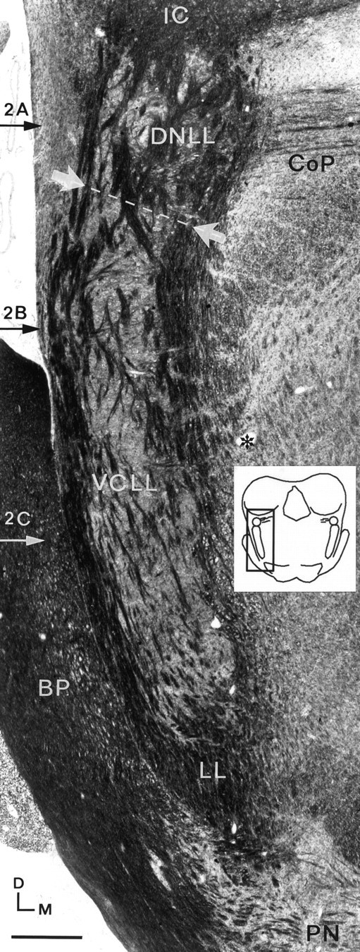
Photomicrograph of a Woelcke- and cresyl violet-stained frontal section through the cat brainstem.Horizontal arrows labeled 2A–2C indicate the approximate levels of the corresponding horizontal sections shown in Figure 2. The border between the DNLL and VCLL is indicated withwhite arrows and a dotted line. The lemniscal fibersencapsulate and pierce the VCLL and the DNLL in a continuous system. The lemniscus is supplied medially by ascending auditory fibers from the superior olivary complex and the dorsal cochlear nucleus crossing the midline in the reticular formation (asterisk). The thinner fiber fascicles of the commissure of Probst pierce the lemniscus from the medial side at the level of the DNLL. Scale bar, 500 μm. BP, Brachium pontis; CoP, commisure of Probst; D, dorsal; LL, lateral lemniscus; M, medial;PN, pontine nuclei.
Fig. 2.
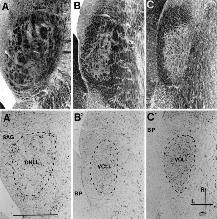
Photomicrographs of pairs of adjacent horizontal sections through the lateral lemniscus at the correspondingly labeled levels in Figure 1. The sections in each pair have been stained for myelin and cells (Woelcke and cresyl violet; A–C) and cells only (thionin; A′–C′). A andA′ are at the level of the DNLL; the others are through the VCLL. The cellular area, inside the tube of external fibers, is marked by a dotted line in A′–C′. Differences in cytoarchitecture between the DNLL and VCLL have been used as criteria for defining the border between the two in the present study. The DNLL (A′) is seen to be populated by uniformly large cells, which occur in irregular groups between the thick, unstained fiber fascicles. The VCLL (B′, C′), in contrast, appears to contain neurons of various sizes, mainly medium-sized. The cells are more evenly dispersed, particularly in the ventral part where the cell density is also larger (C′), in conformity with the less prominent internal fiber component (C). Scale bar, 1 mm. BP, Brachium pontis; L, lateral; R, rostral;SAG, sagulum.
Surgical procedures, injection, and histochemistry of tracer. For the tracing experiments, nine young adult cats of either sex (weight, 2.0–4.4 kg) were used (Table1). The animals were anesthetized with intramuscular injection of a mixture of ketamine (57 mg/kg) and hydrazide chlorhydrate (8.6 mg/kg). Atropine sulfate was given to minimize the production of bronchial secretions during the procedure. Aqueous solutions of 10% BDA (lysine-fixable biotinylated dextran; molecular weight, 10,000; D-1956; Molecular Probes, Eugene, OR) in 0.1m phosphate buffer, pH 7.3, was injected iontophoretically into the left IC by passing pulses of positive current (7 μA; duty cycle, 7 sec) for 20–30 min. The micropipette was positioned stereotactically into the CNIC following the coordinates of a cat brain atlas (Reinoso-Suárez, 1961). The electrophysiological maps of Merzenich and Reid (1974) and Servière et al. (1984) were used as a guide for placing injections in different frequency regions (Fig. 3). The micropipette was left in situ for 15 min.
Table 1.
Summary of BDA injections in the cat CNIC
| Animal | Frequency (kHz)1-a | Plane of sectioning |
|---|---|---|
| 930071-b | 0.5–2 | Transverse |
| 95006 | 1–4 | Horizontal |
| 96020 | 2–4 | Transverse |
| 96017 | 4–6 | Transverse |
| 95042 | 3–6 | Sagittal |
| 950411-b | 5–10 | Sagittal |
| 940701-b | 8–12 | Transverse |
| 93002 | 15–20 | Transverse |
| 960281-b | 30–45 | Transverse |
Estimated frequency at injection site based on Servière et al. (1984).
Reconstructed cases.
Fig. 3.
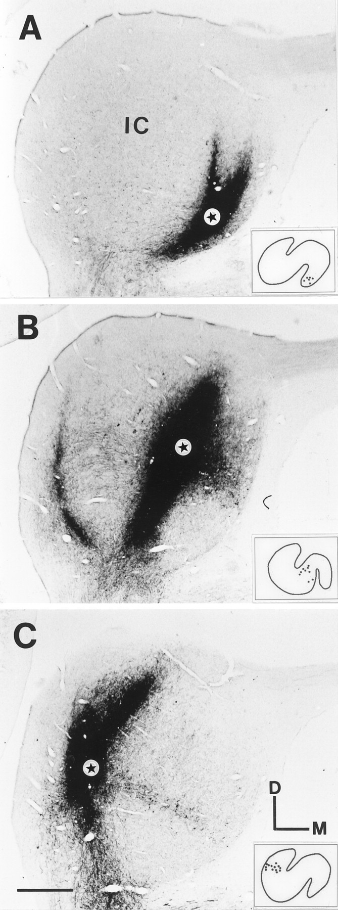
Photomicrographs of transverse sections through the center of the BDA injection sites in the left IC of the three cats used in Figures 4-12. Stars show the location of the tip of the injection electrode. Insets, Distribution of retrogradely labeled cells in a representative section through the lateral superior olive. The injections cover the high-frequency region (A), middle-frequency region (B), and low-frequency region (C). The estimated ranges of frequency representations covered by the injections are given in Table 1. Some of the staining represents labeling of the local fiber plexus in the IC (Malmierca et al., 1995). Scale bar, 1 mm.
After 13–25 d survival, the animals were deeply anesthetized with an overdose of pentobarbital and transcardially perfused with lukewarm Ringer’s solution followed by a mixture of freshly depolimerized 0.2% glutaraldehyde and 4% paraformaldehyde in 0.1 m phosphate buffer, pH 7.3. The brains were stored in 30% buffered sucrose. Complete series of sections were cut at 40 μm with a freezing microtome in one of three standard planes (Table 1). The BDA labeling was visualized with an avidin-biotinylated HRP procedure (ABC; Vectastain, Vector Laboratories, Burlingame, CA), as outlined byVeenman et al. (1992). Sections spaced at intervals of 160–240 μm were counterstained with cresyl violet. Sections were photographed through a Zeiss (Thornwood, NY) Axiophot light microscope (Figs4A, 5).
Fig. 4.
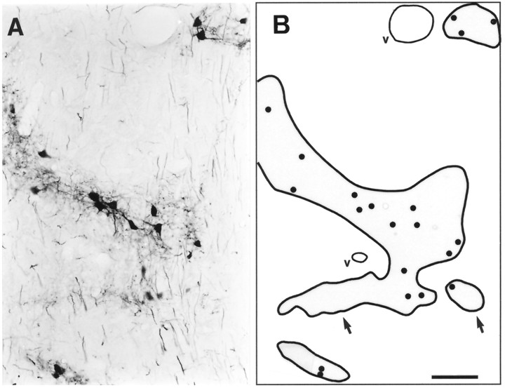
A, Photomicrograph showing patches of labeling in the VCLL after BDA injections into the ipsilateral IC (same case as shown in Fig. 5). B, Camera lucida drawing of the same region showing the location of the labeled cell somata (points), the patch borders (thick contour lines), and blood vessels (thin contour lines, v). The user focused through the thickness of the specimen to draw the patch border at the maximum extent of labeling. This explains the small deviations between the patch borders in the photomicrograph (A) and the contour lines in the drawing (B, arrows). The points and contour lines were digitized and served as a basis for the 3-D reconstructions. Scale bar, 100 μm.
Fig. 5.
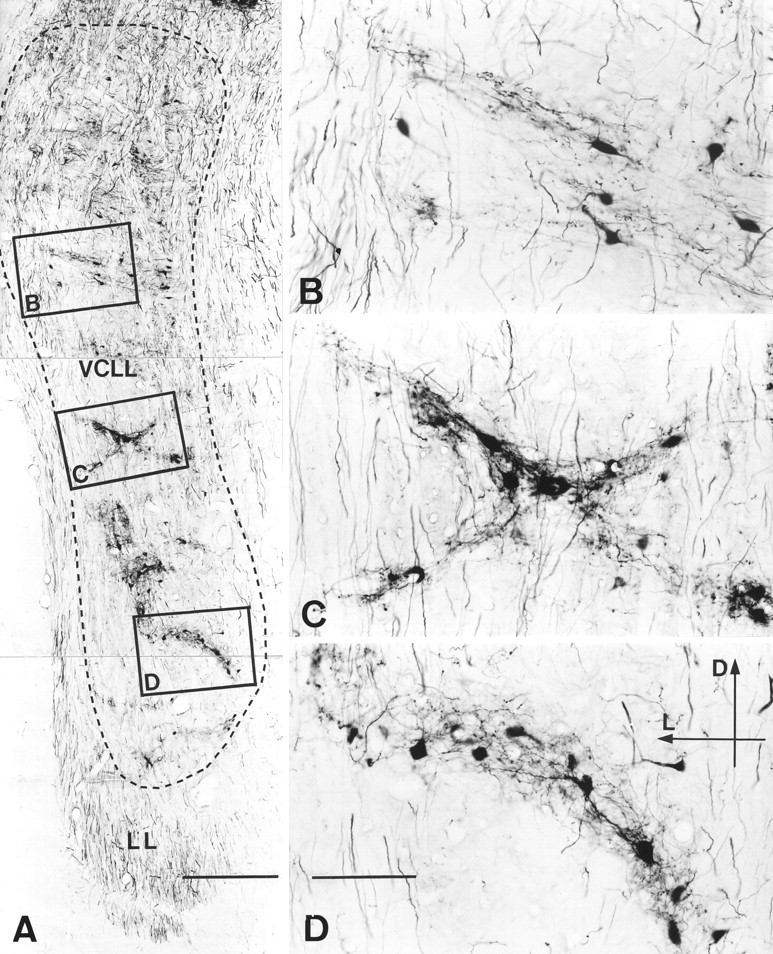
Photomicrographs of a transverse section through the VCLL of cat 94070 illustrating the labeling after BDA injection into the middle-frequency region of the ipsilateral IC (compare Fig.3B). The framed regions are shown at higher magnification in B–D. The labeled structures are distributed in 2-D patches (3-D clusters) composed of labeled cell bodies, proximal dendrites, and a terminal fiber plexus. The patches are shaped as irregular bands ∼150 μm thick. Elongated, labeled cell bodies and primary dendrites appear oriented in parallel with the long axis of the bands. Labeled axons en passage course vertically throughout the tissue. Dorsally, the labeling is more diffuse. Scale bars: A, 1 mm; B–D, 200 μm.D, Dorsal; L, lateral. LL, lateral lemniscus.
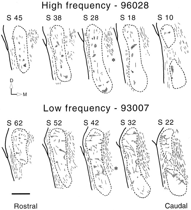
Data analysis and computer-assisted 3-D reconstruction.Detailed camera lucida drawings of labeled structures and anatomic landmarks in the region of the lemniscal nuclei were made in every second section at a total magnification of 84× (Fig.6), using a Leitz (Wetzlar, Germany) Diaplan microscope. Four cases were reconstructed in three dimensions (animals 93007, 94070, 95041, and 96028; Table 1). The camera lucida drawings were aligned with the aid of the surface contours, vessels, and fiducial marks (made with a fine needle inserted through the tissue blocks before sectioning) and digitized using a modified version of the program MicroTrace (Leergaard and Bjaalie, 1995; Leergaard et al., 1995). From each drawing, the external border of the VCLL, inside the tube of lemniscal fibers, was recorded as a contour line. Labeled neurons were recorded as single points, whereas the patches of labeled structures(plexuses of labeled terminal fibers, labeled cells, and dendrites) were recorded as contour lines surrounding the individual patches (Fig.4). The contour lines were used for calculating the volume of the VCLL and the labeled subspace (Table2). For comparisons of numbers of labeled cells in different parts of the VCLL, we used simple profile counts. Thus, labeled cells were plotted without adjustment for double counts (for review of unbiased counting methods, cf. Coggeshall, 1992). However, we have used these data for studying major relativedifferences within individual animals only. In this context, the bias introduced by the counting method is negligible.
Fig. 6.
Series of camera lucida drawings illustrating the patches of labeling in the VCLL after injections in the high-frequency region (compare Fig. 3A) and the low-frequency region (compare Fig. 3C) of the ipsilateral CNIC. Asterisks indicate lemniscal fibers crossing in the reticular formation (compare Fig. 1). In the high-frequency case, most of the labeling is located in the lateral half of the VCLL. The low-frequency case shows a larger amount of labeling. In this case, the patches occur throughout most of the VCLL, and topographic differences are difficult to define. The central part of the VCLL, however, contains less labeling than the medial and lateral borders. Scale bar, 1 mm. D, Dorsal;M, medial; S, section number.
Table 2.
Estimated volume of the VCLL, number of labeled cells, and labeled volume
| Volume (mm3) | No. of cells | Labeled volume (mm3) | |
|---|---|---|---|
| Low frequency, 93007 | |||
| Dorsal third | 2.08 | 148 | 0.18 |
| Middle third | 1.59 | 238 | 0.22 |
| Ventral third | 1.43 | 348 | 0.12 |
| VCLL total | 5.10 | 734 | 0.52 |
| Middle frequency, 94070 | |||
| Dorsal third | 1.75 | 440 | 0.26 |
| Middle third | 1.35 | 375 | 0.23 |
| Ventral third | 1.44 | 368 | 0.17 |
| VCLL total | 4.54 | 1183 | 0.66 |
| High frequency, 96028 | |||
| Dorsal third | 1.89 | 90 | 0.06 |
| Middle third | 1.73 | 295 | 0.08 |
| Ventral third | 1.27 | 115 | 0.05 |
| VCLL total | 4.89 | 505 | 0.19 |
For 3-D visualization and analysis of the VCLL and the distribution of labeling (Figs. 7-12), we used software solutions developed at the Department of Anatomy, University of Oslo (E.O. Andersen and J.G. Bjaalie) for the Silicon Graphics (Mountain View, CA) Indigo 2 and O2 work stations (Leergaard et al., 1995, Bjaalie et al., 1997a). The software was partly based on available modules in Open Inventor, release 2 (a commercially available graphics tool kit). Tissue shrinkage attributable to histological processing was estimated to be 10% (range, 8–12%). To maintain correct proportions in the reconstructions, the z values (distances between section planes) assigned to each section were reduced correspondingly. The contour lines (VCLL external border and contour lines surrounding the plexuses of labeling) were used for resynthesizing the surface of the VCLL (Figs. 7,8) and the surface of individual clusters of labeling inside the VCLL (Fig. 8). The program Nuages (Geiger, 1993) was used to create a surface model of the individual clusters. The model consists of separate clusters and clusters that were interconnected with thin bridges. To create a maximum fit to the original data, an interactive procedure was used to define whether clusters were continuous (bridged) or segregated. In all cases there was little variation among clusters in the density of labeled terminal fibers. To demonstrate the distribution of labeling, each cluster was subsequently filled with a random pattern of dots with a given density. The dot representation is used in Figures9, 10 and11A–C. In Figures11D–F and 12, it serves as a basis for a pseudo-color-coded density map. The density maps were produced by dividing a particular projection (view along the long axis of VCLL) of the reconstruction into squares of ∼5 × 5 μm using a grid. Each square was assigned a color corresponding to the density of cells within a radius of 100 μm centered on the square. Linear warping of data from multiple animals was obtained by aligning the surface contours (Fig. 10).
Fig. 7.
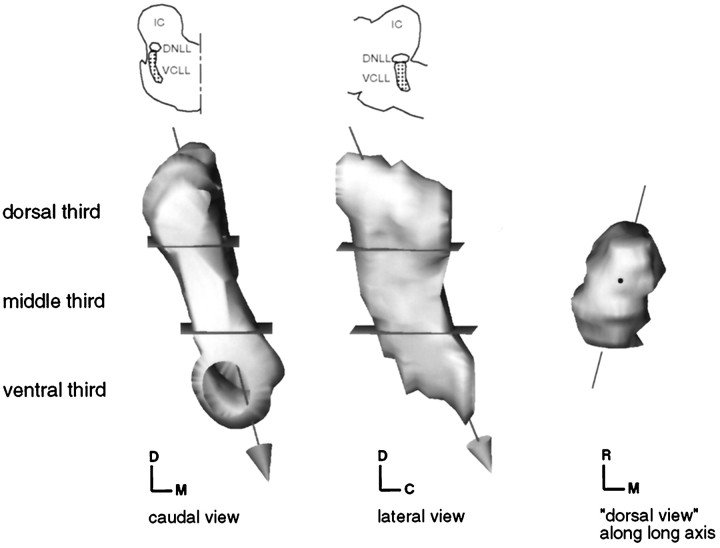
Computer-generated surface model of the VCLL, showing how the VCLL arbitrarily has been divided into dorsal, middle, and ventral thirds. The arrow represents the long axis of the VCLL. The angle of views from caudal, lateral, and dorsal (along the long axis of the VCLL), correspond the views used in Figures 8-12.C, Caudal; D, dorsal; M, medial; R, rostral.
Fig. 8.
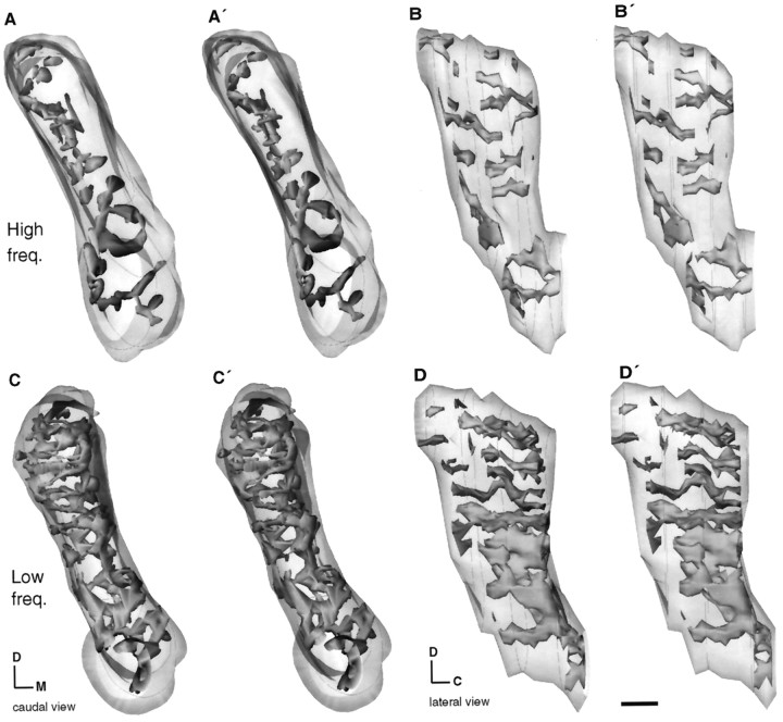
Computer-generated stereo pairs showing the 3-D distribution of labeling within the VCLL in the high-frequency case (A, A′, B, B′; case 96028; Fig.3A) and the low-frequency case (C, C′, D, D′; case 93007; Fig. 3C). The external surface of the VCLL is represented as a transparent surface. The outer boundaries of the clusters containing labeling are visualized as solid surfaces. The stereopairs A and A′ andC and C′ are viewed from caudal, whereasB and B′ and D andD′ are viewed from lateral. To see a 3-D image, the viewer must cross the eye axis to let the pair of images merge. InA and A′ and B andB′, the clusters, as a general rule, are located adjacent to the rostrolateral surface of the VCLL. In Cand C′ and D and D′, the clusters show a wider distribution with a mediocaudal predominance. Scale bar, 500 μm. C, Caudal; D, dorsal; M, medial; R, rostral.
Fig. 9.
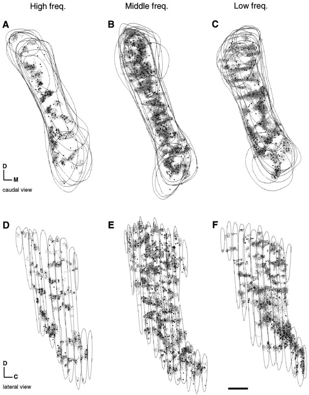
Computer 3-D dot maps showing the distribution of labeled fibers and cells within the VCLL, of the high-frequency case (A, D; case 96028; Fig. 3A), the middle-frequency case (B, E; case 94070; Fig.3B), and the low-frequency case (C, F; case 93007; Fig. 3E). InA–C, the reconstructions are viewed from caudal; inD–F they are viewed from lateral. Labeled fibers are shown as gray dots, retrogradely labeled cells asblack (larger) dots, and the external surface of the VCLL as contour lines. The density of labeled cells within the clusters does not show any systematic variation between the cases and the three parts of the VCLL. Scale bar, 500 μm. C, Caudal; D, dorsal; M, medial; R, rostral.
Fig. 10.
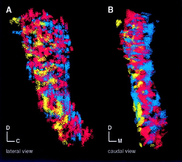
Reconstructions from the three individual cases (high-, middle-, and low-frequency cases; Fig. 9) superimposed in the same model. Yellow dots represent the distribution of labeling in the high-frequency case, red dots the middle-frequency case, and blue dots the low-frequency case. The angles of view are the same as in Figure 9. In the caudal view (B) a gradual transition from lateral (yellow) toward central (red) and medial (blue) is observed. In several places, a complementary shape of the individual clusters is seen. For example, in the dorsal third, the elongated band-like clusters of the low-frequency case (blue) fit the holes of the more continuous pattern of labeling in the middle-frequency case (red). The clusters of the low-frequency case (blue) are mostly located laterally but partly embrace and penetrate the regions occupied by labeling of the other frequencies. C, Caudal;D, dorsal; M, medial; R, rostral.
Fig. 11.
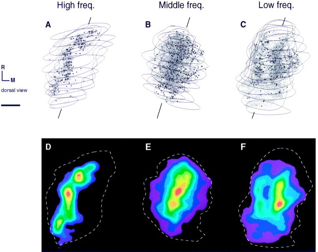
Dot maps (A–C) and color-coded density maps (D–F) of the distribution of labeling in the VCLL. The high-frequency case is shown in A and D, the middle-frequency case inB and E, and the low-frequency case inC and F (for further details, see legend to Fig. 9). The angle of view in all images is from dorsal, skewed slightly toward rostral and lateral, following the long axis of the VCLL, as indicated in Figure 7. For descriptive purposes, we introduce a reference line from rostromedial to caudolateral tentatively through the middle of the VCLL. The color gradient in D–F shows the highest densities in red and the lowest inviolet. Densities <5% of the maximum value are not shown. Scale bar, 500 μm. M, Medial; R, rostral.
Fig. 12.
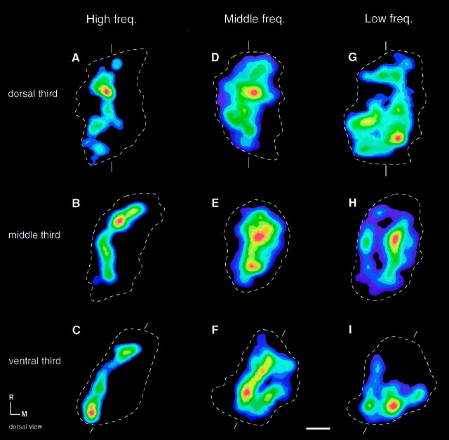
Color-coded density maps of the distribution of labeling in the three defined parts of the VCLL, dorsal, middle, and ventral thirds, in each of the high-, middle-, and low-frequency cases. The reference lines at the top and bottomindicate the tentative orientation of the larger diameter in the cross-sections. From dorsal to ventral, the angle of the reference lines shifts ∼30° (from a rostral-to-caudal orientation dorsally, to a rostromedial-to-caudolateral orientation ventrally). The maps show a tendency for a banded distribution, most prominent in the ventral and middle thirds. Several shapes are visible, e.g., U-shaped bands and finger-like extensions in the middle- and low-frequency cases. Presentation is otherwise as in Figure 7D–F. Scale bar, 500 mm. M, Medial; R, rostral.
Real-time rotations on the computer screen and stereo images (Fig. 8) were used for inspection from various angles and for perceiving depth. Computer images (Figs. 7-12) were printed on Tektronix Phaser 440 and Phaser 450 printers.
RESULTS
Shape and size of the VCLL
The DNLL and VCLL are embedded in the lateral lemniscus, which stretches from the rostral border of the superior olivary complex to the base of the IC. It constitutes the direct continuation of the trapezoid body after a sharp bend in the rostral and dorsal directions. At the level of the VCLL, the fibers form two incompletely separated components: external and internal (Figs.1, 2). The external fibers form a peripheral tube, which is flattened mediolaterally. They have a straight course and are more clearly fasciculated dorsally. The internal fibersintermingle with the cells and may include the ascending axons of these neurons. In agreement with this notion, these fibers are more numerous and more clearly fasciculated dorsally, where they have a rather tortuous course. At the level of the DNLL, the internal fibers form thick fascicles that merge with the external fiber component.
We have used cytoarchitectonic and myeloarchitectonic criteria as a basis for outlining the VCLL (Figs. 1, 2). In our drawings and 3-D reconstructions, we intended to include only the cellular area and not the tube of external fibers (Fig. 2, compare the cell myelin- and Nissl-stained horizontal sections). [For a documentation of the detailed cell morphology, see Adams (1979) and Glendenning et al. (1981).]
As judged from individual sections (Figs. 1, 2, 5A,6) and 3-D reconstructions (Figs.7-12), the VCLL is shaped like a flattened cylinder with the long axis oriented dorsoventrally and the larger diameter of the oval cross-section oriented rostrocaudally. The larger diameter is smaller ventrally, where it deviates ∼30° from the sagittal plane (Figs. 7,8B,D, 9D–F, 12). Measured from our 3-D reconstructions, the VCLL extends ∼4–5 mm dorsoventrally, 0.8 mm mediolaterally, and 1–2 mm rostrocaudally. The volume shows little variation among the reconstructed cases with a mean of 4.8 mm3 (Table 2).
Prompted by the present analyses, we have arbitrarily divided the VCLL into three parts: the dorsal, middle, and ventral thirds, respectively (Fig. 7). They basically correspond with the three divisions introduced by Adams (1979). The dorsal third approximately corresponds to the intermediate nucleus of Glendenning et al. (1981). We used these subdivisions as a basis for evaluating both differences in the distribution and extent of labeling within and between cases (Table2).
Injection sites
Our nine injections together cover the whole range of audible frequency representations in the CNIC (Table 1), as determined by previously published tonotopic maps obtained with electrophysiological techniques (Rose et al., 1963; Merzenich and Reid, 1974; Semple and Aitkin, 1979) and [14C]2-deoxiglucose experiments (Servière et al., 1984). In the following, the distribution of labeling in three representative animals will be illustrated and analyzed in detail: case 93007, injected in the low-frequency region; 94070, in the middle-frequency region; and 96028, in the high-frequency region (Table 1, Fig.3).
The center of each injection site can be readily identified (Fig.3A–C, stars). Judging by the extent of staining at the injection site, the three injections are segregated, although together they cover the larger part of the tonotopic axis of the CNIC. The resulting labeling in the lower auditory nuclei, which is in agreement with previous studies on the ascending and descending connections of the cat CNIC (Adams, 1979), shows that the active uptake sites in the three illustrated cases occupy clearly segregated compartments along the well known tonotopic axis of the IC. This is illustrated by the distribution of labeling in the lateral superior olive (Fig. 3, insets) which is in accordance with well established tonotopic map of Tsuchitani and Boudreau (1969).
General features of labeling
As expected, the VCLL is labeled only on the side ipsilateral to the injection site. The labeling includes cell somata, dendritic processes, thick and thin axons, and terminal plexuses, including en passant and terminal varicosities. This is in accordance with reports by Merchán et al. (1994) and Merchán and Berbel (1996), who described retrograde transport of BDA to cell bodies and anterograde transport into the collaterals of retrogradely labeled neurons that innervate the injection sites in the rat IC. In our sections, the labeled structures appear intermingled in well defined, mostly flattened or elongated patches (Figs. 5, 6), separated by unlabeled cellular areas (as judged by comparing pairs of BDA-incubated and cresyl violet-stained sections). The density of labeled fibers within the patches is approximately the same throughout the VCLL, whereas the density of labeled cells is uneven. Elongated cells and dendrites tend to be oriented along the length of the patches. Only few labeled somata or dendrites occur outside the patches (Fig. 5D). Solitary thick and vertically oriented labeled fibers pass through the patches (Fig. 5). These axons may ascend from more ventral parts of the VCLL or from other sources connected with the IC injection sites. The reconstructions show that the two-dimensional (2-D) patches form 3-D clusters (compare Figs. 6, 8).
The extent of labeling differs among cases (Table 2). The totallabeled volume (i.e., the tissue volume occupied by clusters of labeling) and the total number of labeled cells are largest in the middle-frequency case and smallest in the high-frequency case. The extent of labeling also differs along the dorsoventral axis of the VCLL. The differences in labeled volume and cell numbers among the cases are most conspicuous in the dorsal third. The highest amount of labeling was found in the dorsal third in the middle-frequency case. These quantitative differences could be related both to the size and the dorsoventral location of the injection sites. In our middle-frequency case, in which the injection site is relatively large and seems to involve also the ventral part of the dorsal cortex of the IC (Fig. 3B), the labeling in the dorsal third of the VCLL is heavier than in the other cases.
Shape and size of clusters
The clusters of labeling illustrated in Figures 5 and 6 and in dot maps (Fig. 9) are shown to advantage in the stereo pairs (Fig. 8). The individual clusters appear mostly elongated, with a highly variable thickness (down to 100 μm) and a length up to 2 mm. They exhibit a systematic variation in size and shape among the dorsal, middle, and ventral thirds of the VCLL. There are also differences among the three cases.
In the high- and low-frequency cases, the clusters in the ventral and middle thirds appear like mostly vertically oriented irregular plates interconnected by thin bridges. In the dorsal third, they are smaller, elongated (band-like), narrow, and tortuous and tend to be oriented rostrocaudally. In the middle-frequency case (Fig. 9B,E), the clusters form a more continuous system, which appears like a winding central core with peripheral extensions, whereas in the dorsal third, on the contrary, it consists of small, rounded clusters that merge into a spongeous pattern (also see Fig. 5A). This dorsoventral difference is also present in a reconstruction from another, sagittally sectioned middle-frequency case (95041; Table1, reconstruction not shown). A possible interpretation would be that the more continuous system of labeling in the middle frequency case is a “negative image” of the clusters of the other frequencies. The shape, size, and location of the labeled clusters thereby suggest an interdigitation of clusters assigned to different frequency band representations. This interpretation is supported by the model shown in Figure 10, where the three reconstructions are superimposed.
Topographic organization
In all cases, the labeled clusters are found at all dorsoventral and rostrocaudal levels (Figs. 6, 8-10). In the horizontal domain, however, the distribution of labeling (Figs. 6, 8-12) varies as a function of the location of the injection sites along the tonotopic axis of the IC. The distribution pattern is complicated, and differences between cases are difficult to see in individual sections (Fig. 6). The 3-D reconstructions, however, reveal a mediolateral distribution gradient with high frequencies represented mainly laterally and middle and lower frequencies progressively more medially (Figs. 8-12). In the following, we will describe the three cases in detail.
In the high-frequency case, an angle of view from caudal shows that the labeling is concentrated in the lateral half of the VCLL (Figs.8A, 9A, 10B). In the middle-frequency case, the labeling appears evenly distributed in the rostrocaudal dimensions but tends to avoid the medial and lateral borders of the complex (Fig. 9B,E). In the low-frequency case, the clusters occur throughout most of the VCLL. However, in the ventral and middle thirds, the labeling is skewed toward the medial and caudal surfaces, with four to six finger-like extensions along the lateral surface and into the central parts of the nucleus (Figs.8C, stereo view required, 9C). In the dorsal third, the labeling is more evenly distributed.
An angle of view from dorsal (Fig. 11), along the “dorsoventral” long axis of the VCLL (as shown in Fig. 7, arrows), is helpful for further understanding the topographic differences. For descriptive purposes, we introduce a horizontal reference line from rostromedial to caudolateral through the middle of the VCLL. The labeling in the high-frequency case is largely confined to the lateral half (Fig. 11A). In the middle- and low-frequency cases, the distribution of labeling is more widespread (Fig. 11B,C, respectively). However, in the middle-frequency case, there is a zone of higher density of labeling centered on the reference line (Fig.11B). In the low-frequency case, by contrast, there is a high-density zone on each side of the reference line, with the higher density of labeling medially (Fig. 11C). The same distribution gradients are shown in the color-coded density maps for the VCLL as a whole (Fig. 11D–F) and in more detail in each third from dorsal to ventral (Fig. 12).
Some further topographical details are revealed in Figure 12. In the high-frequency case (Fig. 12A–C), the labeling is confined to a laminar subspace, visible as rostrocaudally oriented bands in the lateral half of each image. In the middle-frequency case (Fig. 12D–F), the highest densities of labeling are located in the center with gradually decreasing densities toward the external border. The high densities (red andyellow) have a banded distribution, particularly in the ventral two-thirds (Fig. 12E,F). In the low-frequency case (Fig. 12G–I), the highest densities are located in the medial half, with extensions toward lateral. The high densities (from red to blue) form a band-like pattern also in the ventral two-thirds (Fig.12H,I).
DISCUSSION
By combined tract-tracing methods and computer-assisted 3-D reconstructions, we have provided anatomic evidence in cat for topographic connections between the VCLL and the IC. The labeling pattern has three main characteristics: (1) labeled cell bodies, dendrites, and terminal fibers of similar frequencies colocalize in distinct clusters; (2) the shape and size of clusters differ from ventral to dorsal; and (3) there is a topographic organization, with low-frequency clusters predominating medially and high-frequency clusters predominating laterally. The present data therefore indicate that a tonotopic organization is present in the VCLL and in its connections. However, this topography is different and unique compared with other auditory structures and may serve functions other than mere frequency coding.
Clustering
The clustered pattern of projection from the VCLL to frequency-specific domains in the IC conforms with previous observations in cat (van Noort, 1969; Roth et al., 1978; Adams, 1979;Glendenning et al., 1981; Henkel and Spangler, 1983; Whitley and Henkel, 1984; Oliver, 1987; Glendenning and Hutson, 1998). The present study complements these studies by demonstrating the 3-D organization of the clusters (previously depicted as 2-D patches) and the colocalization of labeled somata, dendritic processes, and terminal fields of axonal collaterals (originating in the lower auditory centers projecting to the IC and locally in the VCLL; cf. Whitley and Henkel, 1984). Our material, as well as corresponding BDA experiments in rat, shows that the space between the labeled clusters contains unlabeled cells (Merchán and Berbel, 1996, their Fig. 3). This demonstrates that the clustering is a primary feature not merely caused by molding factors such as fascicles of unlabeled fibers (internal fibers; see Figs. 1, 2). Such fibers could originate from sources not connected with the IC [i.e., principal cells of the medial nucleus of the trapezoid body (Glendenning et al., 1981; Spangler et al., 1985), octopus cells of the posteroventral cochlear nucleus (Cant, 1997;Schofield and Adams, 1997), and spherical and globular cells of the anteroventral cochlear nucleus (Friauf and Ostwald, 1988; Smith et al., 1991, 1993)]. The cluster pattern contrasts the laminar tonotopic organization of other brainstem auditory nuclei, e.g., the inferior colliculus (Malmierca et al., 1995), but it is a well known feature from other brain regions such as the striatum (Gaybriel and Ragsdale, 1978; Gerfen, 1992) and the nearby pontine nuclei (Brodal and Bjaalie, 1997).
Tonotopy
The interdigitating, clustered pattern has hampered previous attempts to reveal a tonotopic organization of the VCLL. In the present study, however, using sophisticated 3-D computerized analyses, we have demonstrated a topographic distribution pattern, which most probably represents the substrate for a tonotopic organization.
A horizontal frequency gradient axis has been demonstrated previously in the VCLL of the rat (Merchán and Berbel, 1996). A concentric organization was proposed, with low frequencies represented peripherally and high frequencies in the center. In the ventral half of the VCLL, however, the high-frequency zone came to the lateral border of the complex (Merchán and Berbel, 1996, their Fig. 8), in accordance with the situation in the cat.
Our findings are compatible with the data shown in two electrophysiological studies of cat (Aitkin et al., 1970) and rabbit (Batra and Fitzpatrick, 1997). Aitkin et al. (1970) inserted electrodes vertically and recorded best frequency responses to pure tone stimulation. Their Figure 1 illustrates a case in which the electrode passed medial to the junction between the DNLL and VCLL and then penetrated the VCLL obliquely from dorsomedial to ventrolateral. As the electrode passed through the VCLL, a full sequence of best frequencies from low to high was recorded. This was interpreted as a dorsoventral tonotopic organization. However, given the angle of the electrode penetration, the findings of Aitkin et al. (1970) are consistent with the mediolateral tonotopic gradient demonstrated in the present study. More recently, Batra and Fitzpatrick (1997) have recorded single units in the medial region of the rabbit VCLL with best frequencies <2 kHz.
The present observations are also compatible with previous anatomic studies. After injections of horseradish peroxidase in frequency-specific regions of the IC, Adams (1979) showed retrogradely labeled cells throughout the dorsoventral extent of the VCLL. With the use of anterograde labeling after injections of [3H]leucine in the VCLL, Whitley and Henkel (1984)likewise concluded that the VCLL has a widespread and diffuse projection to the CNIC. However, in agreement with our findings, an injection centered on the lateral part of the VCLL (Whitley and Henkel, 1984, their Fig. 4C) produced heavier labeling in the high-frequency region of the CNIC (their Fig. 3). After an injection in the medial part of the VCLL (Whitley and Henkel, 1984, their Fig. 4E), a higher amount of labeling occurred in the low-frequency part of the CNIC. Indeed, Whitley and Henkel (1984) discussed that their smallest injection located in the medial edge of the VCLL could be interpreted as an evidence of a mediolateral tonotopic organization.
Dorsoventral differences
Although the overall topographic gradient is the same throughout the dorsoventral aspect of the VCLL, the dorsal third differs from the middle and ventral thirds in other ways: (1) the cluster pattern is different (Fig. 8); (2) the extent of labeling suggests that it has a different projection to the IC, also including the dorsal cortex (Whitley and Henkel, 1984); (3) it is made of presumably excitatory cells, in contrast to the glycinergic and GABAergic cells of the ventral two-thirds (Winer et al., 1995; Saint Marie et al., 1997; Vater et al., 1997; Riquelme et al., 1998); and (4) it receives a glycinergic input from the medial nucleus of the trapezoid body (Glendenning et al., 1981; Spangler et al., 1985).
Functional significance
In most auditory nuclei, tonal frequencies are represented in continuous laminar compartments (for review, see Irvine, 1992). In this context, the clustered, interdigitating tonotopic pattern found in the VCLL represents an exception. Other neural systems, however, contain organizational principles resembling those reported here for the VCLL. The pontine nuclei, intercalated in the main pathway from the cerebral cortex to the cerebellum, have been shown to contain a loose laminar organization of both corticopontine fiber and pontocerebellar neurons (Nikundiwe et al., 1994; Bjaalie et al., 1997b). At a small scale, both fibers and cells, topographically related to specific cerebral and cerebellar areas, are located in clusters. At a large scale, the clusters tend to occupy laminar subspaces, which are usually thick and probably overlapping. The interdigitating, frequency-specific clusters seen in the VCLL (Fig. 10) resemble this pattern. This organization may create a large interface between compartments connected to different parts of the CNIC, comparable to the situation in the pontine nuclei, in which there seem to be extensive interfaces between different terminal fields originating in different parts of the cerebral cortex. Also in the cerebral cortex, axonal clusters are viewed as devices for maximizing neuronal diversity rather than devices for segregation of information in separate processing streams (Malach, 1994). In the VCLL, the pattern of widespread, interdigitating clusters, confined within distinct compartments, could likewise serve to create diversity of neuronal properties.
The functional implication of this pattern would depend on the spatial relationship of the dendritic arbors to the cluster borders. In our study, the labeled dendritic processes are regularly confined to a cluster. Reservations, however, have to be made for unlabeled dendrites. Vater et al. (1997) demonstrated that calyx-like terminals on VCLL cells form collaterals contacting dendritic processes of nearby cells. They therefore suggested that VCLL dendrites could extend into multiple tonotopic areas. The few Golgi studies of dendritic arbors (Willard and Martin, 1983; Willard and Ryugo, 1983) and electrophysiological studies of tuning curves (Guinan et al., 1972;Covey and Casseday, 1991, 1995) in the lateral lemniscal nuclei are, however, inconclusive in this regard.
Then what is the role in audition of the clustered, interdigitating tonotopic pattern of the VCLL? Currently, there is good psychophysical evidence to suggest that pitch perception needs not only spectral (Goldstein, 1973; Yost, 1982) but also temporal (Moore and Rosen, 1979) information. There is a wealth of data indicating that the VCLL neurons are well suited to analyze the temporal properties of the auditory signals (Covey and Casseday, 1991; for extensive review, seeCovey and Casseday, 1995). Licklider (1951), and later Meddis and Hewitt (1991), have launched a model to explain human pitch perception. This model proposes the summation of the autocorrelated cell responses across frequency-selective channels as a mechanism for extracting a combination of both temporal and spectralinformation. The model has been tested successfully for various types of pitch stimuli (Meddis and O’Mard, 1997). It requires a neuronal circuitry that can generate (1) delayed versions of the input signal, (2) convergence of the delayed signals onto single cells, and (3) convergence between different frequency channels. The VCLL could meet these requirements by (1) the multiple ladder-like collaterals of the long lemniscal afferents, (2) the local collaterals with ventral neurons supplying successively more dorsal neurons (Whitley and Henkel, 1984), and (3) the spatially specific, but still interdigitating, frequency representations. The detailed circuitry of the VCLL, however, remains to be verified, and it is uncertain how the inhibitory nature of the neurons in the ventral two-thirds of the VCLL would suit the model. The present findings, nevertheless, open new avenues to further investigation of this hitherto poorly understood link in the ascending auditory pathway.
Footnotes
Financial support was provided by Spanish Direccíon General de Enseñanza Superior Grants PB95-1129 and PB97-1326 (to M.A.M) and by grants from the Research Council of Norway, The Nansen foundation, and The Jahre foundation (to J.G.B.). M.S.M. was supported by the Spanish Ministerio de Educación y Ciencia and the Commission of the European Union. V.M.B. was supported by the Spanish Ministerio de Educación y Ciencia. We thank Enrique López-Poveda, Douglas L. Oliver, Kirsten K. Osen, and Enrique Saldaña for valuable comments and I. Plaza, F. R. Nodal, G. F. Lothe, C. Knudsen, and E. O. Andersen for expert technical assistance.
Correspondence should be addressed to Dr. Manuel S. Malmierca, Laboratorio de Neurobiología de la Audición, Departamento de Biología Celular y Patología, Facultad de Medicina. Universidad de Salamanca. C/Alfonso X el Sabio, s/n Campus “Miguel de Unamuno,” 37007 Salamanca, Spain.
REFERENCES
- 1.Adams JC. Ascending projections to the inferior colliculus. J Comp Neurol. 1979;183:519–538. doi: 10.1002/cne.901830305. [DOI] [PubMed] [Google Scholar]
- 2.Adams JC. Projections from octopus cells of the posteroventral cochlear nucleus to the ventral nucleus of the lateral lemniscus in cat and human. Auditory Neurosci. 1997;3:335–350. [Google Scholar]
- 3.Aitkin LM, Anderson DJ, Brugge JF. Tonotopic organization and discharge characteristics of single neurons in the nuclei of the lateral lemniscus of the cat. J Neurophysiol. 1970;33:421–440. doi: 10.1152/jn.1970.33.3.421. [DOI] [PubMed] [Google Scholar]
- 4.Batra R, Fitzpatrick DC. Neurons sensitive to interaural temporal disparities in the medial part of the ventral nucleus of the lateral lemniscus. J Neurophysiol. 1997;78:511–515. doi: 10.1152/jn.1997.78.1.511. [DOI] [PubMed] [Google Scholar]
- 5.Bajo VM, Merchán MA, Malmierca MS, Bjaalie JG, Nodal FR. The topographical organization from the dorsal nucleus of the lateral lemniscus to the central nucleus of the inferior colliculus in the cat. Assoc Res Otolaryngol Abstr. 1997;20:165. [Google Scholar]
- 6.Bjaalie JG, Daehlen M, Stensby TV. Surface modelling of biomedical data. In: Tveito A, Daehlen M, editors. Numerical methods and software tools in industrial mathematics. Birkhauser; Boston: 1997a. pp. 9–26. [Google Scholar]
- 7.Bjaalie JG, Sudbø J, Brodal P. Corticopontine terminal fibres form small scale clusters and large scale lamellae in the cat. NeuroReport. 1997b;8:1651–1655. doi: 10.1097/00001756-199705060-00019. [DOI] [PubMed] [Google Scholar]
- 8.Blackstad TW, Osen KK, Mugnaini E. Pyramidal neurones of the dorsal cochlear nucleus: a Golgi and computer reconstruction study in cat. Neuroscience. 1984;13:827–854. doi: 10.1016/0306-4522(84)90099-x. [DOI] [PubMed] [Google Scholar]
- 9.Brodal P, Bjaalie JG. Salient anatomic features of the cortico-ponto-cerebellar pathway. Prog Brain Res. 1997;114:227–249. doi: 10.1016/s0079-6123(08)63367-1. [DOI] [PubMed] [Google Scholar]
- 10.Bourk TR, Mielcarz JP, Norris BE. Tonotopic organization of the anteroventral cochlear nucleus of the cat. Hear Res. 1981;4:215–241. doi: 10.1016/0378-5955(81)90008-3. [DOI] [PubMed] [Google Scholar]
- 11.Caicedo A, Herbert H. Topography of descending projections from the inferior colliculus to auditory brainstem nuclei in the rat. J Comp Neurol. 1993;328:377–392. doi: 10.1002/cne.903280305. [DOI] [PubMed] [Google Scholar]
- 12.Caicedo A, d’Aldin C, Puel J-L, Eybalin M. Distribution of calcium-binding protein immunoreactivities in the guinea pig auditory brainstem. Anat Embryol. 1996;194:465–487. doi: 10.1007/BF00185994. [DOI] [PubMed] [Google Scholar]
- 13.Coggeshall RE. A consideration of neural counting methods. Trends Neurosci. 1992;15:9–13. doi: 10.1016/0166-2236(92)90339-a. [DOI] [PubMed] [Google Scholar]
- 14.Covey E. The monaural nuclei of the lateral lemniscus: parallel pathways from cochlear nucleus to midbrain. In: Merchán MA, Juiz JM, Godfrey DA, Mugnaini E, editors. The mammalian cochlear nuclei: organization and function. Plenum; New York: 1993. pp. 321–334. [Google Scholar]
- 15.Covey E, Casseday JH. The monaural nuclei of the lateral lemniscus in an echolocating bat: parallel pathways for analyzing temporal features of sound. J Neurosci. 1991;11:3456–3470. doi: 10.1523/JNEUROSCI.11-11-03456.1991. [DOI] [PMC free article] [PubMed] [Google Scholar]
- 16.Covey E, Casseday JH. The lower brainstem auditory pathways. In: Popper AN, Fay RR, editors. Hearing in bats. Springer; New York: 1995. pp. 235–295. [Google Scholar]
- 17.Friauf E, Ostwald J. Divergent projections of physiologically characterized rat ventral cochlear nucleus neurons as shown by intra-axonal injection of horseradish peroxidase. Exp Brain Res. 1988;73:263–284. doi: 10.1007/BF00248219. [DOI] [PubMed] [Google Scholar]
- 18.Gaybriel AM, Ragsdale CW. Histochemically distinct compartments in the striatum of human, monkey and cat demonstrated by acetylchlolinesterase staining. Proc Natl Acad Sci USA. 1978;75:5723–5726. doi: 10.1073/pnas.75.11.5723. [DOI] [PMC free article] [PubMed] [Google Scholar]
- 19.Geiger B. Three-dimensional modelling of human organs and its application to diagnosis and surgical planning. Report 2105. Institut National de Recherche en Informatique et en Automatique; Sophia-Antipolis, France: 1993. [Google Scholar]
- 20.Gerfen CR. The neostriatal mosaic: multiple levels of compartmental organization in the basal ganglia. Annu Rev Neurosci. 1992;15:285–320. doi: 10.1146/annurev.ne.15.030192.001441. [DOI] [PubMed] [Google Scholar]
- 21.Glendenning KK, Hutson KA. Lack of topography in the ventral nucleus of the lateral lemniscus. Microsc Res Tech. 1998;41:298–312. doi: 10.1002/(SICI)1097-0029(19980515)41:4<298::AID-JEMT3>3.0.CO;2-N. [DOI] [PubMed] [Google Scholar]
- 22.Glendenning KK, Brunso-Bechtold JK, Thompson GC, Masterton RB. Ascending auditory afferents to the nuclei of the lateral lemniscus. J Comp Neurol. 1981;197:673–704. doi: 10.1002/cne.901970409. [DOI] [PubMed] [Google Scholar]
- 23.Goldstein JL. An optimum processor theory for the central formation of the pitch of complex tones. J Am Soc Audiol. 1973;54:1496–1515. doi: 10.1121/1.1914448. [DOI] [PubMed] [Google Scholar]
- 24.Guinan JJ, Jr, Norris BE, Guinan SS. Single auditory units in the superior olivary complex: II. Locations of unit categories and tonotopic organization. Int J Neurosci. 1972;4:147–166. [Google Scholar]
- 25.Henkel CK, Spangler KM. Organization of the efferent projections of the medial superior olivary nucleus in the cat as revealed by HRP and autoradiographic tracing methods. J Comp Neurol. 1983;221:416–428. doi: 10.1002/cne.902210405. [DOI] [PubMed] [Google Scholar]
- 26.Irvine DRF. Physiology of the auditory brainstem. In: Popper A, Fay RR, editors. The mammalian auditory pathway: neurophysiology. Springer; New York: 1992. pp. 153–231. [Google Scholar]
- 27.Leergaard TB, Bjaalie JG. Semi-automatic data acquisition for quantitative neuroanatomy. MicroTrace—computer programme for recording of the spatial distribution of neuronal populations. Neurosci Res. 1995;22:231–243. doi: 10.1016/0168-0102(95)00899-6. [DOI] [PubMed] [Google Scholar]
- 28.Leergaard TB, Lakke EAJF, Bjaalie JG. Topographical organization in the early postnatal corticopontine projection: a carbocyanine dye and 3-D computer reconstruction study in the rat. J Comp Neurol. 1995;361:77–94. doi: 10.1002/cne.903610107. [DOI] [PubMed] [Google Scholar]
- 29.Licklider JCR. A duplex theory of pitch perception. Experimentia. 1951;7:128–133. doi: 10.1007/BF02156143. [DOI] [PubMed] [Google Scholar]
- 30.Malach R. Cortical columns as devices for maximizing neuronal diversity. Trends Neurosci. 1994;17:101–104. doi: 10.1016/0166-2236(94)90113-9. [DOI] [PubMed] [Google Scholar]
- 31.Malmierca MS. Computer-assisted three-dimensional reconstructions of Golgi impregnated cells in the rat inferior colliculus Doctoral thesis. Universities of Oslo and Salamanca; 1991. [Google Scholar]
- 32.Malmierca MS, Blackstad TW, Osen KK, Karagülle T, Molowni RL. The central nucleus of the inferior colliculus in rat: a Golgi and computer reconstruction study of neuronal and laminar structure. J Comp Neurol. 1993;333:1–27. doi: 10.1002/cne.903330102. [DOI] [PubMed] [Google Scholar]
- 33.Malmierca MS, Rees A, Le Beau FEN, Bjaalie JG. Laminar organization of frequency-specific local axons within and between the inferior colliculi of the guinea pig. J Comp Neurol. 1995;357:124–144. doi: 10.1002/cne.903570112. [DOI] [PubMed] [Google Scholar]
- 34.Malmierca MS, Le Beau FEN, Rees A. The topographical organization of descending projections from the central nucleus of the inferior colliculus in guinea pig. Hear Res. 1996;93:167–180. doi: 10.1016/0378-5955(95)00227-8. [DOI] [PubMed] [Google Scholar]
- 35.Malmierca MS, Merchán M, Bajo VM, Bjaalie JG. The ventral nucleus of the lateral lemniscus in cat is tonotopically organized. Assoc Res Otolaryngol Abstr. 1997;20:164. [Google Scholar]
- 36.Meddis R, Hewitt MJ. Virtual pitch and phase sensitivity of a computer model of the auditory periphery I: pitch identification. J Am Soc Audiol. 1991;89:2866–2882. [Google Scholar]
- 37.Meddis R, O’Mard LP. A unitary model of pitch perception. J Am Soc Audiol. 1997;102:1811–1820. doi: 10.1121/1.420088. [DOI] [PubMed] [Google Scholar]
- 38.Merchán MA, Berbel P. Anatomy of the ventral nucleus of the lateral lemniscus in rats: a nucleus with a concentric laminar organization. J Comp Neurol. 1996;372:245–263. doi: 10.1002/(SICI)1096-9861(19960819)372:2<245::AID-CNE7>3.0.CO;2-3. [DOI] [PubMed] [Google Scholar]
- 39.Merchán MA, Saldaña E, Plaza I. Dorsal nucleus of the lateral lemniscus in the rat: concentric organization and tonotopic projection to the inferior colliculus. J Comp Neurol. 1994;342:259–278. doi: 10.1002/cne.903420209. [DOI] [PubMed] [Google Scholar]
- 40.Merchán MA, Bajo VM, Malmierca MS, Bjaalie JG (1996) The laminar organization of the nuclei of the lateral lemniscus (NLL): a tracer and computer reconstruction study in cat. Paper presented at the 2nd International Symposium on Acoustical Signal Processing in the Central Auditory System, Prague, September.
- 41.Merchán MA, Malmierca MS, Bajo VM, Bjaalie JG. The nuclei of the lateral lemniscus: old views and new perspectives. In: Syka J, editor. Acoustical signal processing in the central auditory system. Plenum; New York: 1997. pp. 211–226. [Google Scholar]
- 42.Merzenich MM, Reid MD. Representation of the cochlea within the inferior colliculus of the cat. Brain Res. 1974;77:397–415. doi: 10.1016/0006-8993(74)90630-1. [DOI] [PubMed] [Google Scholar]
- 43.Moore BCJ, Rosen SM. Tune recognition with reduced pitch and interval information. J Exp Psychol. 1979;31:229–240. doi: 10.1080/14640747908400722. [DOI] [PubMed] [Google Scholar]
- 44.Morest DK. The laminar structure of the inferior colliculus of the cat. Anat Rec. 1964;148:314. [Google Scholar]
- 45.Nikundiwe AM, Bjaalie JG, Brodal P. Lamellar organization of pontocerebellar neuronal populations. A multi-tracer and 3-D computer reconstruction study in the cat. Eur J Neurosci. 1994;6:173–186. doi: 10.1111/j.1460-9568.1994.tb00259.x. [DOI] [PubMed] [Google Scholar]
- 46.Oliver DL. Projections to the inferior colliculus from the anteroventral cochlear nucleus in the cat: possible substrate for binaural interaction. J Comp Neurol. 1987;264:24–46. doi: 10.1002/cne.902640104. [DOI] [PubMed] [Google Scholar]
- 47.Oliver DL, Morest DK. The central nucleus of the inferior colliculus in the cat. J Comp Neurol. 1984;222:237–264. doi: 10.1002/cne.902220207. [DOI] [PubMed] [Google Scholar]
- 48.Pirsig W, Noda Y, Lehmann I. Tonotope Abbildung der Cochlea im Nucleus cochlearis ventralis des Meerschweinchens. Arch Klin Exp Ohren Nasen Kehlkopfheilk. 1972;202:494–500. [PubMed] [Google Scholar]
- 49.Reinoso-Suárez F. Topographischer Hirnatlas der Katze für experimental-physiologische Untersuchungen. Merck; Darmstadt: 1961. [Google Scholar]
- 50.Riquelme R, Merchán MA, Ottersen OP. GABA and glycine in the ventral nucleus of the lateral lemniscus: an inmunocytochemical and in situ hybridization study in rat. Assoc Res Otolaryngol Abstr. 1998;21:93. doi: 10.1002/cne.1111. [DOI] [PubMed] [Google Scholar]
- 51.Rose JE, Greenwood DD, Goldberg JM, Hind JE. Some discharge characteristics of single neurons in the inferior colliculus of the cat: I. Tonotopical organization, relation of spike-counts to tone intensity, and firing patterns of single elements. J Neurophysiol. 1963;26:314–319. doi: 10.1152/jn.1963.26.2.321. [DOI] [PubMed] [Google Scholar]
- 52.Roth GL, Aitkin LM, Andersen RA, Merzrnich MM. Some features of the spatial organization of the central nucleus of the inferior colliculus of the cat. J Comp Neurol. 1978;182:661–680. doi: 10.1002/cne.901820407. [DOI] [PubMed] [Google Scholar]
- 53.Saint Marie RL, Shneiderman A, Stanforth DA. Patterns of γ-aminobutyric acid and glycine immunoreactivities reflect structural and functional differences of the cat lateral lemniscal nuclei. J Comp Neurol. 1997;389:264–276. doi: 10.1002/(sici)1096-9861(19971215)389:2<264::aid-cne6>3.3.co;2-y. [DOI] [PubMed] [Google Scholar]
- 54.Schofield BR, Cant NM. Ventral nucleus of the lateral lemniscus in guinea pigs: cytoarchitecture and inputs from the cochlear nucleus. J Comp Neurol. 1997;379:363–385. doi: 10.1002/(sici)1096-9861(19970317)379:3<363::aid-cne4>3.0.co;2-1. [DOI] [PubMed] [Google Scholar]
- 55.Schreiner CE, Langner G. Laminar fine structure of frequency organization in the auditory midbrain. Nature. 1997;388:383–386. doi: 10.1038/41106. [DOI] [PubMed] [Google Scholar]
- 56.Semple MN, Aitkin LM. Representation of sound frequency and laterality by units in central nucleus of cat inferior colliculus. J Neurophysiol. 1979;42:1626–1639. doi: 10.1152/jn.1979.42.6.1626. [DOI] [PubMed] [Google Scholar]
- 57.Servière J, Webster WR, Calford MC. Isofrequency labelling revealed by a combined [14C]-2-deoxyglucose, electrophysiological, and horseradish peroxidase study of the inferior colliculus of the cat. J Comp Neurol. 1984;228:463–477. doi: 10.1002/cne.902280403. [DOI] [PubMed] [Google Scholar]
- 58.Smith PH, Joris PX, Carney LH, Yin TCT. Projections of physiologically characterized globular bushy cell axons from the cochlear nucleus of the cat. J Comp Neurol. 1991;304:387–407. doi: 10.1002/cne.903040305. [DOI] [PubMed] [Google Scholar]
- 59.Smith PH, Joris PX, Yin TCT. Projections of physiological characterized spherical bushy cell axons from the cochlear nucleus of the cat: evidence for delay lines to the medial superior olive. J Comp Neurol. 1993;331:245–260. doi: 10.1002/cne.903310208. [DOI] [PubMed] [Google Scholar]
- 60.Spangler K, Warr WB, Henkel CK. The projections of principal cells of the medial nucleus of the trapezoid body in the cat. J Comp Neurol. 1985;238:249–262. doi: 10.1002/cne.902380302. [DOI] [PubMed] [Google Scholar]
- 61.Tsuchitani C, Boudreau JC. Single unit analysis of cat superior olive S-segment with tonal stimuli. J Neurophysiol. 1969;29:684–697. doi: 10.1152/jn.1966.29.4.684. [DOI] [PubMed] [Google Scholar]
- 62.van Noort J. The structure and connections of the inferior colliculus: an investigation of the lower auditory system. Proefschrift. van Gorcum; Leiden, the Netherlands: 1969. [Google Scholar]
- 63.Vater M, Covey E, Casseday JH. The columnar region of the ventral nucleus of the lateral lemniscus in the big brown bat (Eptesicus fuscus): synaptic arrangements and structural correlates of feedforward inhibitory function. Cell Tissue Res. 1997;289:223–233. doi: 10.1007/s004410050869. [DOI] [PubMed] [Google Scholar]
- 64.Veenman CL, Reiner A, Honig MG. Biotinylated dextran amine as an anterograde tracer for single- and double-labeling studies. J Neurosci Methods. 1992;41:239–254. doi: 10.1016/0165-0270(92)90089-v. [DOI] [PubMed] [Google Scholar]
- 65.von Békésy G. Experiments in hearing. McGraw-Hill; New York: 1960. [Google Scholar]
- 66.Whitley JM, Henkel CK. Topographical organization of the inferior collicular projection and other connections of the ventral nucleus of the lateral lemniscus in the cat. J Comp Neurol. 1984;229:257–270. doi: 10.1002/cne.902290210. [DOI] [PubMed] [Google Scholar]
- 67.Willard FH, Martin GF. The auditory brainstem and some of their projections to the inferior colliculus in the North American opossum. Neuroscience. 1983;10:1203–1232. doi: 10.1016/0306-4522(83)90109-4. [DOI] [PubMed] [Google Scholar]
- 68.Willard FH, Ryugo DK. Anatomy of the central auditory system. In: Willot JF, editor. The auditory psychobiology of the mouse. Thomas; Springfield, IL: 1983. pp. 201–304. [Google Scholar]
- 69.Winer JA, Larue DT, Pollak GD. GABA and glycine in the central auditory system of the mustache bat: structural substrates for inhibitory neuronal organization. J Comp Neurol. 1995;355:317–353. doi: 10.1002/cne.903550302. [DOI] [PubMed] [Google Scholar]
- 70.Woelcke M. Eine neue Methode der Markscheidenfärbung. J Psychol Neurol. 1942;51:199–202. [Google Scholar]
- 71.Yost WA. The dominance region and ripple noise pitch: a test of the peripheral weighting model. J Am Soc Audiol. 1982;72:416–425. doi: 10.1121/1.388094. [DOI] [PubMed] [Google Scholar]


