1. Motivation and objectives
The near-wall resolution requirement to accurately resolve the boundary layer in wall-bounded flows remains one of the largest obstacles in large-eddy simulation (LES) of high-Reynolds-number engineering applications. Chapman (1979) estimated that the number of grid points necessary for a wall-resolved (WR) LES scales as NWR ~ Re9/5, where Re is the characteristic Reynolds number of the problem. A more recent study by Choi & Moin (2012), using more accurate correlations for the skin friction coefficients, concluded that NWR ~ Re13/7, which is far too expensive for many practical engineering applications and not very different from the NDNS ~ Re37/14 scaling required for direct numerical simulation (DNS) where all the relevant scales of motion are resolved.
By modeling the near-wall flow such that only the outer layer of the boundary layer is resolved, the grid point requirements for wall-modeled (WM) LES scale at most linearly with increasing Reynolds number, NWM ~ Re. Therefore, wall-modeling stands as the most feasible approach for most engineering applications. Several strategies for modeling the near-wall region have been explored in the past. The most popular and well-known wall-models are the traditional wall-stress models (or approximate boundary condition) and detached eddy simulation (DES) and its variants. Approximate boundary condition models compute the wall stress using either the law of the wall (Schumann 1975; Deardorff 1970; Piomelli et al. 1989) or the solution obtained by solving a simplified version of the boundary layer equations close to the wall, e.g., the Reynolds-averaged Navier-Stokes (RANS) equations (Balaras et al. 1996; Cabot & Moin 1999; Kawai & Larsson 2010). DES (Spalart et al. 1997)combines RANS equations close to the wall and LES in the outer layer, with the interface between RANS and LES domains enforced implicitly through the change in the turbulence model.
In order to reduce the computational cost, all above models assume a simplified state of the local near-wall boundary layer, including the shape of the velocity profile, the relative significance of the different terms in the equations solved, and the alignment of the subgrid velocity field with respect to local strain. Furthermore, models involving RANS equations close to the wall are sensitive to the choice of the particular closure and its associated coefficients, as well as the location of the RANS/LES interface. The above wall-model techniques may not be accurate in flow regimes where these assumptions are no longer valid as in transitional or separated flows. Moreover, sensitivities to model parameters or RANS/LES interface locations can limit the predictive capabilities of wall-modeled LES, and their computational complexity may make their implementation a difficult and time-consuming task.
Recently, Bose & Moin (2014) showed promising results using a dynamic slip boundary condition that does not require any prior knowledge of the local boundary layer. However, the computed slip length is sensitive to changes in grid resolution, Reynolds number and subgrid scale (SGS) model. Our goal is to investigate the effects of the slip boundary condition on the first-order statistics of a plane turbulent channel flow in order to obtain the neccessary requirements for building robust wall-models applicable to real-world scenarios.
The paper is organized as follows. In Section 2, we motivate the suitability of the slip boundary condition as a wall-model by considering the filtered Navier-Stokes equations. A-priori testing is performed on filtered DNS data to study the validity of the slip boundary condition. In Section 3, we analyze the slip boundary condition for implicitly filtered LES. For that purpose, we perform a set of LES of turbulent channel flows with slip boundary conditions and study the effect of slip lengths, choice of SGS model, grid resolution, and Reynolds number on first-order statistics such as the mean and root-mean-squared (RMS) velocity profiles. Finally, conclusions are offered in Section 4.
2. Slip boundary condition in the filtered Navier-Stokes equations
2.1. Formulation
Let us consider a wall-bounded flow. For both DNS and wall-resolved LES, the velocity at the wall is given by the no-slip boundary condition
| (2.1) |
where i = 1,2,3 corresponds to the x1, x2 and x3 directions, respectively, and we will interchangeably use u, v, w for u1, u2, u3 (and x, y, z for x1, x2, x3) throughout the paper.
If we interpret LES as the solution of the filtered Navier-Stokes equations, as it is formally derived in most textbooks, the filtering operation in the wall-normal direction will result in non-zero velocities at the wall. This suggests that LES requires a modified wall boundary condition different from the usual no-slip, especially for large filter sizes (or coarse grid resolutions).
Following the above argument, we expand the velocities at the wall as a Taylor series of the filter size Δ around Δ = 0, to get
| (2.2) |
where represents the filter operation and is the velocity at the wall for Δ = 0, which coincides with the no-slip condition used in DNS. Defining the slip length as
| (2.3) |
where n denotes wall-normal direction, Eq. (2.2) can be rearranged, up to first-order approximation, as an effective slip boundary condition of the form
| (2.4) |
Including second- and higher-order terms in Eq. (2.4), which might be neccessary in coarse LES calculations, will result in different slip lengths and even extra intercept terms for each velocity boundary condition in order to get a reasonable representation of the flow at the wall, that is,
| (2.5) |
where repeated indices do not imply summation. The particular expressions for li and βi are obtained by grouping all terms multiplied by ∂/∂Δ into li and collecting the remaining ones in βi. Both li and βi depend formally on the filter shape, size, and instantaneous configuration of the filtered velocity vector at the wall. Such a dependence on the filter and flow configuration is expected to become more relevant as the filter size increases.
The above analysis provides a framework to build general Robin boundary conditions for coarse LES computations, and its validity and suitability is investigated in the remaining sections.
2.2. A-priori testing
A-priori testing of the slip boundary condition was conducted to assess the validity of Eq. (2.4) in filtered turbulent channel flow data. DNS results from del Álamo et al. (2004), Hoyas & Jiménez (2006) and Lozano-Durán & Jiménez (2014) at friction Reynolds numbers of Reτ = 950, 2000 and 4200 were used to perform the analysis.
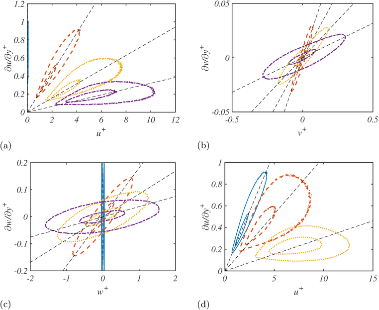
In the following, x, y and z denote streamwise, wall-normal, and spanwise directions, respectively. The friction velocity is denoted by uτ and the channel half-height by δ. In each case, the velocity vector is filtered in the three spatial directions with two different filter shapes: the differential filter from Germano (1986) with the functional filter size proposed by Bose & Moin (2014), and the classic box filter. The resulting filtered data contain and , which can be used to evaluate the goodness of Eq. (2.4) by computing their joint probability density function (PDF) as shown in Figure 1.
Figure 1.
50% and 95% probability contours of the joint probability density function of (a) and , (b) and , and (c) and for box-filtered DNS of turbulent channel flow for Δ = 0 (blue solid line), 0.01δ (red dashed line), 0.02δ (yellow dotted line), and 0.03δ (purple dot-dash line) with Reτ = 950; (d) with for filter size Δ = 0.01δ, Reτ = 950 (blue solid line), 2000 (red dashed line), and 4200 (yellow dotted line).
We will focus first on the differential filter. Following Bose & Moin (2014), the filtered velocity is defined by
| (2.6) |
| (2.7) |
where repeated indices imply summation, lp is related to the filter size with nominal value equal to lnom, and yint is a wall-normal estimation of the beginning of the outer layer. See Bose & Moin (2014) for details. As lp vanishes linearly at the wall, the first-order approximation discussed in Eq. (2.4) renders exact with
| (2.8) |
Hence, the joint PDF for the differential filter corresponds to perfect straight lines with slopes (slip lengths) given by Eq. (2.8).
When the velocities are filtered using a box kernel, which may be a more realistic estimation of the LES velocities in coarse grids, the first-order approximation no longer holds. The joint PDF of the streamwise, wall-normal and spanwise velocities and derivatives for the box filtered case at Reτ = 950 are plotted in Figure 1(a–c). The results show a linear correlation between and on the average sense, which supports the suitability of the slip boundary condition. However, the spread of the joint PDF increases with increasing filter size and the average slopes (related to the slip lengths li) differ for the each velocity component, consistent with our analysis in Section 2.1. Finally, Figure 1 (d) shows the Reynolds number dependence of the joint PDF for a constant filter size in outer units. As already observed for varying filter width, the spread of the PDF increases with the Reynolds number too, but the correlation between velocity and its wall-normal derivative remains.
The above results suggest the necessity of different slip lengths in each direction in an actual LES implementation, at least for coarse grids as it is usually the case in wall-modeled LES. This was also argued in Eq. (2.5) in the context of truncation errors for the Taylor expansion of the velocities at the wall and will be tested in the next section.
3. Slip boundary condition in implicitly filtered LES
In most LES calculations, the filter operation is not explicitly defined. Instead, the truncation error of the numerical scheme and the grid itself are assumed to act as an implicit filter, resolving only those scales that can be represented by the given resolution. However, when the near-wall grid is not fine enough to resolve the very small scales, the no-slip condition produces very poor results (Jimenez & Moser 2000).
It was argued in Section 2.1 that the most general form of the Robin boundary condition, given by Eq. (2.5) should replace the no-slip condition in coarse implicitly filtered LES. The symmetries of the flow can be exploited to further simplify the above expression. For example, when 〈ui〉 = 0, where 〈·〉 denotes ensemble average in homogeneous directions and time, 〈βi〉 must be set to zero.
To study the effects of Eq. (2.5), we perform a set of plane turbulent channel flow simulations with the slip boundary condition at the wall. The above discussion suggests that the appropriate Robin boundary condition consistent with the symmetries of the channel must be of the form
| (3.1) |
Note that we have decided to set β1= 0 without much loss of generality, since its average effect can be absorbed by moving the frame of reference at constant uniform velocity. Another option is to set l1 = 0 along with a non-zero constant value for β1. However, that would generate zero tangential Reynolds stress at the wall which will be shown to be neccessary to avoid large velocity fluctuations near the wall.
The question remains as to what should be the expected role of the slip condition or, in general, of any wall-model based on approximate boundary conditions. In the context of a channel flow driven by a constant mass flow, the first requirement is to provide the correct mean stresses at the wall, that is, an accurate wall momentum drain, which in turn will yield to the correct bulk velocity scaled in wall units. Second, the wall-model should avoid spurious near-wall peaks observed in coarse wall-resolved LES (e.g. Meyers & Sagaut 2007) for the streamwise RMS velocity fluctuations. Both requirements must be accompanied by an effective SGS model responsible for generating healthy turbulent statistics in the interior of the domain, where the wall-model plays a secondary role. This last point is important in order to obtain the correct shape of the mean velocity profile and accurate RMS velocity fluctuations along the entire domain.
3.1. Numerical experiments
We perform a set of LES calculations of a plane turbulent channel flow in order to study the effects of the Reynolds number, grid resolution and SGS model on the optimal slip length defined as the one providing the mean and RMS velocity statistics closest to the reference DNS. The simulations are computed with a staggered second-order finite difference (Orlandi 2000) code and a fractional step method (Kim & Moin 1985) with a third-order Runge-Kutta time advancing scheme (Wray 1990). The size of the channel is 2πδ×2δ×πδ in the streamwise, wall-normal and spanwise directions, respectively, where δ is the channel half-height. The channel flow is driven by imposing a constant mean pressure gradient and the slip boundary condition is used on the top and bottom walls. Periodic boundary conditions are imposed in the streamwise and spanwise directions. All simulations were run for at least 100 eddy turnover times after transients.
We take as baseline case a channel flow at friction Reynolds number Reτ = 2000 and grid resolution 128 × 40 × 64 in the x, y, and z directions, respectively. The SGS model is the dynamic Smagorinsky from Germano et al. (1991) and Lilly (1991) but differs from the usual approach in the averaging procedure, in that it is directly applied to the eddy viscosity and not to the dynamic constant. Given the very coarse resolution at the wall, we impose Neumann boundary conditions for the SGS stress instead of the usual zero-value Dirichlet condition often used in wall-resolved LES.
To study the effects of the grid resolution, we define a coarse mesh and a fine mesh with 102 × 32 × 52 and 152 × 48 × 76 grid points, respectively. The resolutions were chosen such that the first interior point lies in the logarithmic region, or at least is far from the inner-wall peak of the streamwise RMS velocity. The intention is to avoid solving (even partially) the dynamic cycle in the buffer layer, since the wall-normal lengths of the near-wall vortices and streaks scale in viscous units, and that scaling is incompatible with the computational efficiency pursued in wall-modeled LES.
To investigate the effect of the Reynolds number we will consider three cases at Reτ = 950, 2000 and 4200, and the effect of the SGS model will be assessed by comparing results from dynamic and constant-coefficient Smagornisky models (Smagorinsky 1963) with cases without an SGS model. A complete list of cases is summarized in Table 1. Finally, the LES results will be compared with DNS data from del Álamo et al. (2004), Hoyas & Jiménez (2006) and Lozano-Durán & Jiménez (2014).
Table 1.
Tabulated list of cases. The case name indicates SGS model, Reτ and mesh size. Dynamic Smagorinsky model (DSM), constant coefficient Smagorinsky model (SM), and no model (NM). Reτ = 950, 2000, 4200. Coarse (c), base (b), and fine (f).
3.2. Effects of the slip lengths on the flow
A-priori testing of the slip condition in Section 2.2 showed that the filtered velocity vector at the wall is better represented by assuming different slip lengths for each velocity component. To gain a better insight into the physical effects of each individual slip length, we study the changes undergone by the flow when the values of lx, ly, and lz are independently modified.
Although not shown, it was tested that varying lz has a second-order effect on the mean and RMS velocity profiles when compared to changes of the same order in lx and ly. The result is not totally unexpected, since u and v are active components of the mean streamwise momentum balance, while w enters only indirectly. In the remaining sections, we set lz equal to lx.
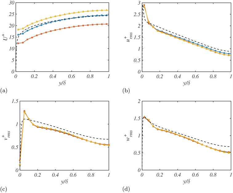
Figure 2 shows the mean streamwise velocity profile and RMS velocity fluctuations for (lx,ly) = (0.005δ,0.005δ), (0.005δ,0.01δ) and (0.01δ,0.005δ). The results reveal that increasing lx (at constant ly) moves up the mean velocity profile by 8%, while increasing ly (at constant lx) has the opposite effect and decreases the mean velocity profile by 16%. In both cases, the RMS velocity fluctuations remain unaltered, except for some small changes close to the wall that are barely visible in the plots.
Figure 2.
The (a) mean streamwise velocity profile, and root-mean-square (b) streamwise, (c) wall-normal, and (d) spanwise velocity profiles for (lx,ly) = (0.005δ,0.005δ) (blue-circles), (0.01δ,0.005δ) (yellow triangles), (0.005δ,0.01δ) (red squares), and DNS (black dashed lines).
The observations for lx and ly may be explained in terms of the non-zero average streamwise slip and mean streamwise momentum balance at the wall. With respect to the latter, increasing ly enhances the uv contribution at the wall, which is translated into a lower mean velocity due to the higher momentum drain at the boundaries. The same argument applies when increasing lx. However, higher lx also implies larger average slip velocities in x, which overcome the previous momentum drain. The net effect is an increase of the mean velocity profile as observed in Figure 2.
A second observation from Figure 2 is that the shape of the mean velocity profile remains constant for different slip lengths, and changes in lx and ly are only reponsible for a shift along the mean velocity axis. We would like to connect the previous result with the classic logarithmic profile for the mean streamwise velocity as obtained from the matched asymptotics argument by Millikan (1938), where
| (3.2) |
with A and B constants defining the slope and intercept of the mean velocity. Assuming that the filter operation does not alter the logarithmic shape of 〈u〉 for the typical filter widths (or grid resolutions), Eq. (3.2) should also hold for LES. Moving one step forward, the integrated mean streamwise momentum balance can be written as
| (3.3) |
where is the subgrid stress tensor. A comparison of the structure of Eqs. (3.2) and (3.3) indicates that it is reasonable to hypothesize that the wall-model mainly influences the intercept A, which is independent of y, while the SGS model controls the y-dependent slope B, also related to the wall-normal mixing of the flow. This is further investigated in the next section.
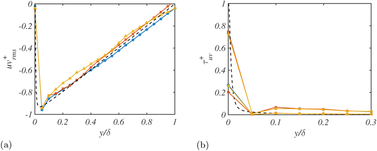
Figure 3 shows the uv, viscous and subgrid stress contributions for different slip lengths. As already shown for the RMS velocities, changes in lx and ly seem to have a negligible effect on the flow except at the walls, which again highlights the limited influence of the wall-model far from the boundaries.
Figure 3.
The (a) uv and (b) viscous stress contributions (smaller) and subgrid stress contributions (larger) for (lx,ly) = (0.005δ,0.005δ) (blue circles), (0.01δ,0.005δ) (yellow triangles), (0.005δ,0.01δ) (red squares), and DNS (black dashed lines).
3.3. Sensitivity to SGS model, Reynolds number, and grid resolution
As discussed in Section 2.1, the slip boundary condition is expected to depend on the instantaneous configuration of the velocity field at the wall. In general, different SGS models will yield to different velocities at the wall which will influence the slip boundary condition.
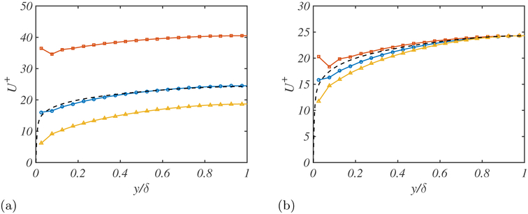
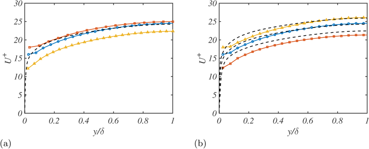
Figure 4 shows the mean velocity dependence on the SGS model. The three cases investigated are the dynamic Smagorinsky, constant coefficient Smagorinsky, and LES without model. In all of the cases, the slip lengths are fixed and equal to 0.005δ such that the velocity profile at the center of the channel for the dynamic Smagorinsky model matches the DNS data. The results reveal that not only the shape but also the total mass flow is highly dependent on the SGS model or on the absence of it. The subgrid scales can be interpreted as the mixing of the flow by the missing small scales. If the SGS model is under-dissipative, the flow becomes more turbulent, which causes the shape of the mean velocity profile to become flatter (enhanced mixing). Besides, for the case without model, the lack of SGS momentum drain at the wall results in strong gradients near the boundaries. On the other hand, if the SGS model is over-dissipative, the flow becomes more laminar and gets closer to a parabolic shape, which corresponds to the equilibrium solution for zero wall-normal momentum transfer.
Figure 4.
(a) Effect of different SGS models on the mean velocity profile for lx = ly = 0.005δ. (b) The mean velocity profiles have been shifted to compare the shapes of the mean velocity profile. Dynamic Smagorinsky model (blue circles), constant coefficient Smagorinsky model (yellow triangles), and no SGS model (red squares) are given for the turbulent channel with Reτ = 2000. DNS (black dashed lines).
The effect on the mass flow rate (in wall units) can be understood by considering the definition of the friction velocity,
| (3.4) |
where νt is the eddy viscosity. In the case of LES without a model, the last term in Eq. (3.4) is zero, that is, lower uτ and hence higher mass flow. For non-zero eddy viscosity, the SGS stress will contribute to increasing uτ, decreasing the mass flow accordingly. The specific change will depend on the details of the SGS model. Note that the coupling between uτ and the slip condition makes these results different from those observed in wall-modeled LES. The previous argument is for variable uτ, but the trends shown in Figure 4 are equally valid for channel flows driven by either constant pressure or constant mass flow rate.
The grid resolution and Reynolds number sensitivity are studied in Figure 5, again maintaining constant slip lengths. Regarding the resolution, coarsening the grid strongly affects the mass flow, i.e., it is substantially increased. This phenomenon is also observed in wall-resolved LES with no-slip boundary condition and is again related to the lack of consistency of wall-normal momentum flux provided by the SGS model. Finally, Figure 5(b) shows a weak dependence of the mean velocity profile on the Reynolds number. The most important difference is the underestimation of the mass flow for the lowest Reynolds number, but overall the optimal slip lengths are quite insensitive to Reτ.
Figure 5.
The effect of the (a) grid resolution and (b) Reynolds number on the mean velocity profile for lx = ly = 0.005δ. (a) 102×32×52 (red squares), 128×40×64 (blue circles), 152×48×76 (yellow triangles). (b) Reτ = 950 (red squares), Reτ = 2000 (blue circles), Reτ = 4200, (yellow triangles). DNS (black dashed lines).
3.4. Expected requirements and a working slip condition
The information from previous sections can be compiled into a list of expected requirements for wall-models based on the slip boundary condition, as shown in table 2.
Table 2.
Effect of the slip condition on the flow and expected wall-model requirements.
| Effect of the slip on the flow | Expected requirements |
|---|---|
| Mean velocity profile shift depends on slip length | Compute the slip lengths that provide the correct mean velocity profile |
| RMS velocity profiles insensitive to changes in slip lengths except at the wall | Provide non-zero Reynolds stress at the wall to avoid spurious peaks of the streamwise RMS velocities |
| Slip boundary condition sensitive to changes in grid resolution and Reynolds number | Robustness to the changes in grid resolution and Reynolds number |
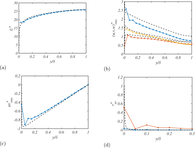
As an example, we show a working slip condition based on the knowledge acquired that prodives the best results in terms of the mean profile and RMS fluctuating velocities in a channel flow at Reτ = 4200. The challenge then is to build wall-models able to dynamically compute the corresponding slip lengths without any empirical information from the flow. This is already under investigation and will be addressed in future publications.
The results are plotted in Figure 6, which shows a good prediction of the mean velocity profile and reasonable RMS velocities below their DNS counterparts, as should be expected from filtered DNS at a high Reynolds number and coarse grid resolution. Unlike previous wall-resolved LES simulations, the RMS are not overpredicted near the walls, which is also an important improvement to emphasize. The increase of the uv contribution at the wall along with the decrease of the viscous stress is characteristic of the wall-normal slip condition and is consistent with the intuitive idea of coarse LES calculations and filtered DNS.
Figure 6.
The (a) mean streamwise velocity profile, (b) root-mean-square streamwise, span-wise, and wall-normal (top to bottom) fluctuation profiles, (c) the uv contribution, and (d) the viscosity contribution (blue circles) and eddy viscosity contribution (red triangles) for the for optimal values of the slip length. DNS (black dashed line).
4. Conclusions
Due to the scaling of grid resolution requirements at the wall in wall-resolved simulations, wall-modeling stands as the most viable approach for most practical engineering applications. In this investigation, we have motivated the slip boundary condition for a wall-model using both first-order approximation of the Taylor series expansion of the velocities with respect to the filter width at the wall, and A-priori testing of filtered DNS data. We have applied the slip boundary condition to implicitly filtered LES using a turbulent channel flow simulation to study the effects of the slip lengths on the flow. The mean velocity profile is shifted depending on the slip lengths, whereas the RMS velocity profiles remain essentially insensitive except for those points close to the wall. We have studied the dependence of first-order statistics on the Reynolds number, SGS model, and grid resolution for given constant slip lengths, and have showed that the mean profile is particularly sensitive to the last two. Finally, we have shown that there exist optimal slip lengths providing accurate mean and RMS velocities in LES and have compiled all the neccessary requirements for wall-models based on the slip boundary condition in order to get satisfactory results.
Acknowledgments
This work was supported by NASA under the Transformative Aeronautics Concepts Program, Grant #NNX15AU93A.
REFERENCES
- Balaras E, Benocci C & Piomelli U 1996. Two-layer approximate boundary conditions for large-eddy simulations. AIAA J. 34, 1111–1119. [Google Scholar]
- Bose ST & Moin P 2014. A dynamic slip boundary condition for wall-modeled large-eddy simulation. Phys. Fluids 26, 015104. [Google Scholar]
- Cabot WH & Moin P 1999. Approximate wall boundary conditions in the large-eddy simulation of high Reynolds number flows. Flow Turbul. Combust 63, 269–291. [Google Scholar]
- Chapman DR 1979. Computational aerodynamics development and outlook. AIAA J. 17, 1293–1313. [Google Scholar]
- Choi H & Moin P 2012. Grid-point requirements for large eddy simulation: Chapman’s estimates revisited. Phys. Fluids 24, 011702. [Google Scholar]
- Deardorff JW 1970. A numerical study of three-dimensional turbulent channel flow at large Reynolds numbers. J. Fluid Mech 41, 453–480. [Google Scholar]
- del Álamo JC, Jiménez J, Zandonade P & Moser RD 2004. Scaling of the energy spectra of turbulent channels. J. Fluid Mech 500, 135–144. [Google Scholar]
- Germano M 1986. Differential filters for the large eddy numerical simulation of turbulent flows. Phys. Fluids 29, 1755–1757. [Google Scholar]
- Germano M, Piomelli U, Moin P & Cabot WH 1991. A dynamic subgrid-scale eddy viscosity model. Phys. Fluids 3, 1760–1765. [Google Scholar]
- Hoyas S & Jiménez J 2006. Scaling of the velocity fluctuations in turbulent channels up to Reτ = 2003. Phys. Fluids 18, 011702. [Google Scholar]
- Jiménez J & Moser RD 2000. Large-eddy simulations: Where are we and what can we expect? AIAA J. 38 605–612. [Google Scholar]
- Kawai S & Larsson J 2010. A dynamic wall-model for large-eddy simulation of high Reynolds number compressible flows Annual Research Briefs, Center for Turbulence Research, Stanford University, pp. 25–37. [Google Scholar]
- Kim J & Moin P 1985. Application of a fractional-step method to incompressible Navier-Stokes equations. J. Comput. Phys 59, 308–323. [Google Scholar]
- Lilly DK 1991. A proposed modification of the Germano subgrid-scale closure method. Phys. Fluids 4, 633–635. [Google Scholar]
- Lozano-Durán A & Jiménez J 2014. Effect of the computational domain on direct simulations of turbulent channels up to Reτ = 4200. Phys. Fluids 26, 011702. [Google Scholar]
- Meyers J & Sagaut P 2007. Is plane-channel flow a friendly case for the testing of large-eddy simulation subgrid-scale models? Phys. Fluids 19, 048105. [Google Scholar]
- Millikan CM 1938. A critical discussion of turbulent flows in channels and circular tubes. In Proceedings of the Fifth International Congress for Applied Mechanics, Harvard and MIT, 12–26 September Wiley. [Google Scholar]
- Orlandi P 2000. Fluid flow phenomena: a numerical toolkit. Kluwer. [Google Scholar]
- Piomelli U, Moin P, Ferziger JH & Kim J 1989. New approximate boundary conditions for large-eddy simulations of wall-bounded flows. Phys. Fluids 1, 1061–1068. [Google Scholar]
- Schumann U 1975. Subgrid-scale model for finite difference simulation of turbulent flows in plane channels and annuli. J. Comput. Phys 18, 376–404. [Google Scholar]
- Smagorinsky J 1963. General circulation experiments with the primitive equations. Mon. Weather Rev. 91, 99–164. [Google Scholar]
- Spalart PR, Jou WH, Strelets M & Allmaras SR 1997. Comments on the feasibility of LES for wings and on a hybrid RANS/LES approach In Advances in DNS/LES, ed. Liu C, Liu Z, pp.137–148. [Google Scholar]
- Wray AA 1990. Minimal-storage time advancement schemes for spectral methods. NASA Tech. Rep. #MS 202 A-1. [Google Scholar]


