Abstract
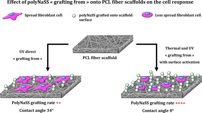
The purpose of this study is to present the poly(caprolactone) (PCL) functionalization by the covalent grafting of poly(sodium styrene sulfonate) on electrospun scaffolds using the “grafting from” technique and evaluate the effect of the coating and surface wettability on the biological response. The “grafting from” technique required energy (thermal or UV) to induce the decomposition of the PCL (hydro)peroxides and generate radicals able to initiate the polymerization of NaSS. In addition, UV irradiation was used to initiate the radical polymerization of NaSS directly from the surface (UV direct “grafting from”). The interest of these two techniques is their easiness, the reduction of the number of process steps, and its applicability to the industry. The selected parameters allow controlling the grafting rate (i.e., degree of functionalization). The aim of the study was to compare two covalent grafting in terms of surface functionalization and hydrophilicity and their effect on the in vitro biological responses of fibroblasts. The achieved results showed the influence of the sulfonate functional groups on the cell response. In addition, outcomes highlighted that the UV direct “grafting from” method allows to moderate the amount of sulfonate groups and the surface hydrophilicity presents a considerable interest for covalently immobilizing bioactive polymers onto electrospun scaffolds designed for tissue engineering applications using efficient post-electrospinning chemical modification.
Introduction
During the past years, electrospinning, a broadly used technique that allows to make porous structures with fibers having dimensions ranging from micrometer to nanometer scale,1 has offered many opportunities to adapt different physical, chemical, and biological properties of a material for biomedical applications. Due to its manufacturing facility, versatility, and adaptability, electrospinning has been used in many fields including biomedical and pharmaceutical applications and other applications such as filtration, solid-phase extraction absorbent, waterproof fabrics, energy applications, biosensor immunoassay, enzyme immobilization, sensing, sound absorption, and antifungal mats.2 This process has been widely studied in tissue engineering to generate nanofiber structures based on different biocompatible and biodegradable polymers and produce scaffolds, which must own fundamental characteristics such as biocompatibility, nontoxicity, porosity, and sufficient mechanical properties.
Tissue engineering and regenerative medicine have been the most studied applications in the biomedical field. Indeed, the formation of a biocompatible and biodegradable biomatrix in three dimensions composed of both a biomaterial and human body cells is the main interest of the electrospinning techniques in the tissue engineering field since it can mimic human tissues composed of nanoscale fiber structures on which cells can attach, organize, and develop.3 Electrospun membranes has been used in tissue engineering for vascular prosthesis,4 cardiac tissue regeneration,5 cell expansion scaffolds,6 protecting cells from oxidative stress conditions,7 bone reconstruction,8,9 cartilage,10 nerve tissue regeneration,11−13 and skin.14
Many polymers are used in electrospinning for various applications, particularly biomedical applications. Among these polymers, polycaprolactone (PCL), with a widely documented use and due to its excellent mechanical properties and slow degradation, is a suitable material for use in tissue engineering applications. The interaction between the biomaterial surface and cells is crucial for biomedical devices. One of the most important physicochemical properties of a biomaterial is the surface wettability as it allows to modulate the protein adsorption and the consequent cell behavior. Against the hydrophobic nature of PCL, which leads to a lack of favorable cell response, different strategies have been established in tissue engineering approaches. These include adsorption of biomolecules onto the surface, the introduction of polar groups by surface treatment, and immobilization of bioactive compounds covalently attached to the scaffold surface.15−21
Our LBPS group’s recent research have shown that cell adhesion and differentiation can be favored using polymers or copolymers bearing anionic groups such as sulfonate, carboxylate, and phosphonate.22−24 The distribution of these ionic groups along the surface creates active sites, which can interact with extracellular proteins, such as fibronectin, implicated in cell response. Poly(sodium styrene sulfonate) (polyNaSS) was successfully grafted onto the surface of different biomaterials (titanium,25−34 PET,35−37 or PCL17−21,38), and many studies achieved in our laboratory demonstrated that the grafting of polyNaSS onto biomaterial surfaces modulate the cellular and bacterial response.28,32,34
As reported in previous studies,18,28,38 one of the benefits of the polyNaSS covalent grafting onto biomaterial surfaces is to allow a great stability of the grafting. Indeed, in vivo prostheses implantations performed in rabbits demonstrate the maintenance of the coating biological activity up to 12 months. Recently, polyNaSS-grafted total hip prostheses (THPs) have been selected and allowed to be tested in a human clinical trial.
In a recent work, assuming that UV irradiations have been used successfully for the surface modification or functionalization of different polymers for biomedical applications, we developed a simple method of radical grafting, which allows the successful grafting of a bioactive polymer (polyNaSS) covalently to PCL surfaces using UV irradiation.38 Reaction parameters have been investigated in order to optimize the yield of polyNaSS grafting onto PCL film surfaces. However, although our laboratory has been successful in developing polyNaSS UV grafting on different biomaterial surfaces,26,27,33,38 until now, this technology has never been applied to electrospun fiber scaffolds.
Several studies report the various possible functionalization of electrospun fiber scaffolds for biomedical applications, but most of them present incomplete research on treatment parameters, complexity of setups, and complexity of the technological design of the used techniques as in the case of co-axial electrospinning or a cylindrical-type multinozzle electrospinning system.2 Our approach is different and is set up to make it easier, efficient, and reproducible as applicable post-electrospinning surface functionalization. In this contribution, we investigate the functionalization of the electrospun PCL fiber scaffold by the covalent grafting of a bioactive polymer to develop potential scaffolds for tissue engineering applications. To achieve this goal, we carried out two “grafting from” techniques: (i) thermal grafting, which requires a surface activation by ozonation, and (ii) UV grafting with or without surface activation by ozonation, and compared the differences between these grafting techniques in terms of surface modification, surface hydrophilicity, and effect of the process steps on the intrinsic PCL properties. Preliminary studies to test the biological responses onto these functionalized electrospun PCL fiber scaffolds were carried out to evaluate the effect of sulfonate groups together with surface hydrophilicity on the fibroblast behavior and demonstrate that these potential scaffolds are biologically acceptable to living cells (biocompatible). For that, fibroblast cell viability and morphology were evaluated onto the functionalized PCL fiber scaffolds.
Results and Discussion
PCL Fiber Scaffold Morphology
The fabrication of the PCL fiber scaffolds is shown schematically in Figure 1. The scanning electron microscopy (SEM) micrographs of the electrospun fiber scaffold microstructure are shown in Figure 2. The electrospinning conditions such as the concentration of polymer solution, applied voltage, flow rate, and tip-to-collector distance were optimized to obtain a continuous stretch of fibers, together with uniform bead-free PCL fibers.
Figure 1.
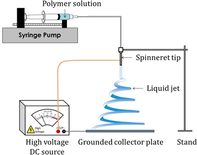
Schematic of electrospinning device.
Figure 2.
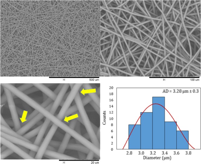
SEM images of the PCL electrospun fiber scaffold at different magnifications and histogram of fiber diameter distribution.
In the biological performance of the electrospun fiber scaffold, fiber diameter and pore diameter have a primordial role to play as it modulates the cell–cell and cell–membrane interactions. Adequate pore size (high porosity) and interconnected pore network are essential criteria for tissue engineering as it enables better cell infiltration and vascularization.39 In this work, from the SEM micrographs, a fiber diameter distribution and an average fiber diameter were determined from a minimum of 50 fibers (Figure 2). All the PCL fibers constituting the scaffolds present a micrometer size (>1 μm), and the average fiber diameter was measured as 3.28 μm ± 0.3 with a narrow diameter distribution from 2.8 to 3.8 μm. Furthermore, we performed pore size measurements as explained above. The pore size of the PCL electrospun fiber scaffold ranged from 6 to 30 μm. As a result of the electrospinning parameters optimized to produce these PCL fiber scaffolds, we obtained uniform pores with a pore diameter quite large for an electrospun fiber membrane designed for tissue engineering applications with the aim of improving the cell penetration.39 Finally, we can observe that the fibers cross in the different layers without having a fusion between them (Figure 2, yellow arrows).
Characterization of polyNaSS Grafting onto PCL Fiber Scaffold Surfaces
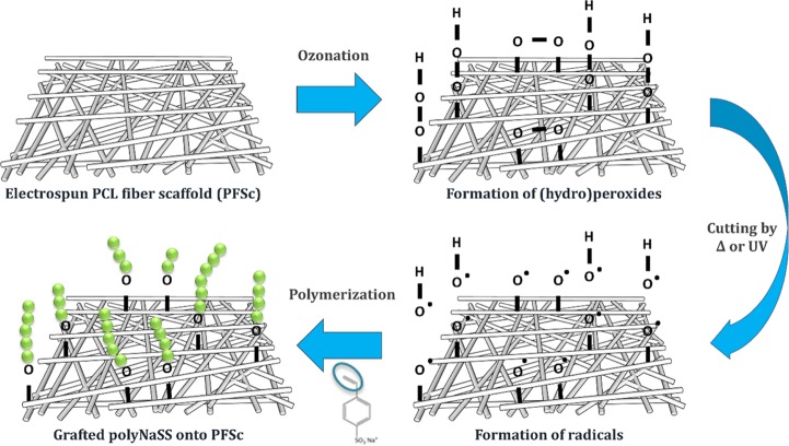
PolyNaSS covalent grafting to the PCL electrospun fiber scaffold surface was performed using the “grafting from” technique (Figure 3). The “grafting from” process included the thermal and UV grafting. As shown previously in studies carried out in our laboratory, radical polymerization enables the covalent grafting of bioactive polymers onto PCL surfaces.17−21,38 This technique requires the activation of the PCL surface by the creation of a surface layer of PCL (hydro)peroxides by an ozone generator. Thereafter, the PCL surfaces were immersed in an aqueous solution of NaSS monomer, and by heating the solution or irradiating it with UV light, the decomposition of the PCL (hydro)peroxide radicals was induced, and these radicals initiate the polymerization of NaSS. Recently, we have demonstrated the possibility of grafting ionic polymers directly to the PCL surface without preliminary activation of the surface; this direct “grafting from” without surface activation allowed us to improve the UV grafting process by removing the activation step.38 To optimize the efficiency of polyNaSS grafting onto PCL surfaces, we have investigated the reaction parameters and identified the optimal process conditions in terms of polymerization time, UV power, activation step, and monomer solution. In this article, we applied the previously established conditions on polyNaSS grafting onto PCL film surfaces.38 We used various techniques to show that the covalent grafting of ionic polymers bearing sulfonate groups was successful onto the electrospun PCL fiber scaffolds. The presence of sulfonate groups onto the grafted PCL surface was demonstrated using surface characterization techniques as toluidine blue (TB) colorimetric method, contact angle measurement, Fourier transform infrared (FTIR) spectra recorded in the attenuated total reflection mode (ATR-FTIR), scanning electron microscopy (SEM) with Oxford energy-dispersive spectroscopy, and X-ray photoelectron spectroscopy (XPS). Possible changes in the intrinsic properties of PCL have been studied using differential scanning calorimetry (DSC). Grafting parameters used in this work are summarized in Table 1.
Figure 3.
PolyNaSS grafting process onto the electrospun PCL fiber scaffold surface.
Table 1. “Grafting from” Technique Parameters: Thermal and UV Grafting.
| parameters | thermal grafting | UV grafting with activation step | UV direct grafting |
|---|---|---|---|
| NaSS monomer solution | 0.7 M | 0.7 M | 0.7 M |
| surface activation | ozonation 20 min | ozonation 20 min | |
| source of radicals | heat at 45 °C | UV irradiation at 160 mW/cm2 | UV irradiation at 160 mW/cm2 |
| polymerization time | 1 and 3 h | 1 h | 1 h |
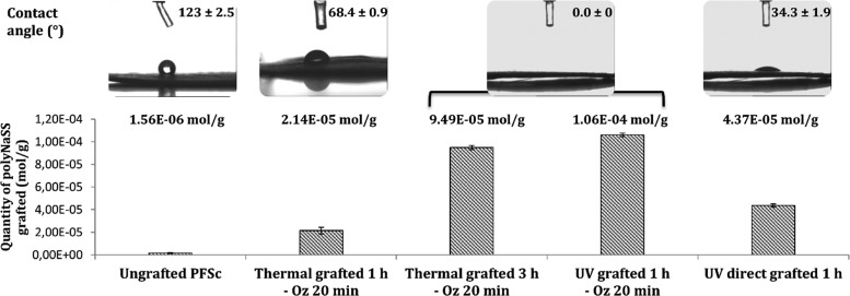
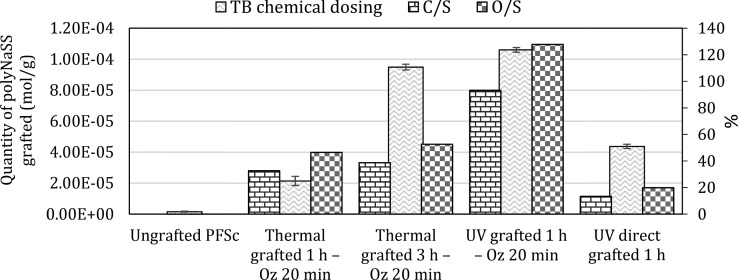
We determined the amount of polyNaSS grafted onto the surface of the different samples using the TB colorimetric method (Figure 4). We found that, as for the grafting onto PCL films,38 the polyNaSS grafting rate onto the PCL fiber scaffold reached a maximum value (1.06 ± 0.15) × 10–4 mol g–1 for UV grafting 1 h with 20 min ozonation (UV grafted 1 h – Oz 20 min). The rates for the two thermal grafting with ozonation 20 min were (2.14 ± 0.29) × 10–5 mol g–1 and (9.49 ± 0.18) × 10–5 mol g–1 after 1 and 3 h of polymerization at 45 °C, respectively. The amount of grafting for the UV direct grafting (without surface activation) was (4.37 ± 0.14) × 10–5 mol g–1. As for the grafted samples, we also dosed the grafting rate onto the ungrafted PCL fiber scaffold. It shows a grafting rate of (1.56 ± 0.34) × 10–6 mol g–1, which means more than a log difference compared to the lowest grafting rate observed on grafted scaffolds. PolyNaSS, which is known to be an ionic and hydrophilic polymer, when grafted on the PCL surface, should lead to a decrease in contact angle compared to an ungrafted PCL surface. We can observe, according to Figure 4, that the presence of polyNaSS grafted onto the PCL fiber scaffold surface leads to contact angles lower than that of the ungrafted PCL fiber scaffold. The ungrafted samples gave a contact angle of 123 ± 2.5°. Thermal grafting 1 h – Oz 20 min results in a contact angle value of 68.4 ± 0.9°, and UV direct grafting 1 h gave a contact angle value of 34.3 ± 1.9°. For the thermal grafting 3 h – Oz 20 min and UV grafting 1 h – Oz 20 min, the contact angle values were 0°, which means that these two techniques gave superhydrophilic surfaces. The higher amounts of grafted poly(NaSS) combined with the significantly lower contact angle value (0°) observed for the thermal grafting 3 h and UV grafting 1 h (both with activation of 20 min ozonation) compared to the thermal grafting 1 h – Oz 20 min and UV direct grafting 1 h suggest a more homogeneous and complete covering of the surface by the grafted polyNaSS. This is likely due to the creation, owing to the ozonation step, of a surface layer of PCL (hydro)peroxides increasing the available radicals leading to the initiation of NaSS polymerization.
Figure 4.
PolyNaSS grafting rates and contact angles for ungrafted and grafted PCL fiber scaffolds (PFSc).
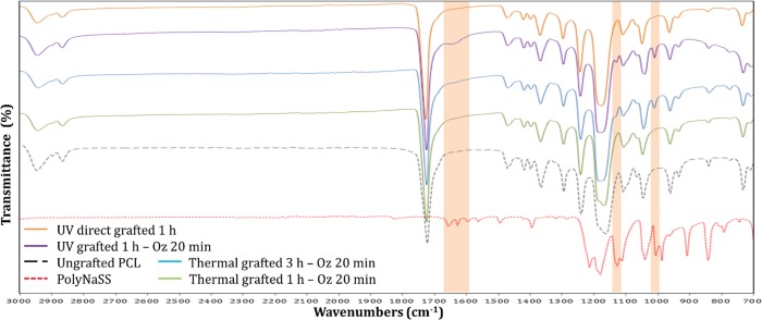
The FTIR spectra showed, in the grafted PCL fiber scaffolds, the presence of specific peaks of the polyNaSS onto the sample surfaces. Figure 5 shows the spectra of polyNaSS, ungrafted PCL fiber scaffold, and four grafted PCL fiber scaffolds with polyNaSS (thermal grafting 1 h – Oz 20 min, thermal grafting 3 h – Oz 20 min, UV grafting 1 h – Oz 20 min, and UV direct grafting 1 h) between 700 and 3000 cm–1. The aromatic ring and the symmetric vibrations of the SO3– groups generated a NaSS doublet (O=S=O) located at 1010 cm–1 (Table 2). The absorption of the sulfonate was detected by the peak at 1130 cm–1, which is also associated with asymmetric vibrations (Table 2). Finally, a series of peaks between 1498 and 1658 cm–1 are attributed to stretching vibrations of bonds (C=C) of the benzene ring (Table 2).
Figure 5.
FTIR-ATR spectrum of grafted polyNaSS onto PCL fiber scaffold surfaces; top to bottom: orange, UV direct grafting 1 h; purple, UV grafting 1 h – Oz 20 min; blue, thermal grafting 3 h – Oz 20 min; green, thermal grafting 1 h – Oz 20 min; black, ungrafted PCL fiber scaffold; red, polyNaSS.
Table 2. Adsorption Bands Characteristics of polyNaSS.
| wavelength (cm–1) | peak intensity | chemical groups & interactions |
|---|---|---|
| 1658–1598 | weak | ν(C=C) of aromatic ring |
| 1411 | medium | ν(SO2) |
| 1184–1130 | high | SO3– (salt) |
| 1040 | high | ν(O=S=O) |
| 1010 | high | aromatic ring |
As expected, the intensity of the peaks is more pronounced on samples with a high amount of polyNaSS grafting. In addition, by comparing FTIR analyses of the polyNaSS grafted PCL fiber scaffolds to the FTIR spectra of polyNaSS-grafted PCL films carried out in a recent work,38 we observed that the grafting on PCL fiber scaffolds makes it possible to point out more characteristics peaks of the polyNaSS than in the case of grafting on PCL films and this can be explained by the difference in the architecture of the two surfaces since the available area on these scaffolds is larger than for a flat surface. However, considering that the PCL is an organic compound, it is difficult to be able to locate the other peaks of polyNaSS among all those of the PCL. The absence of polyNaSS-specific peaks was verified on ungrafted samples.
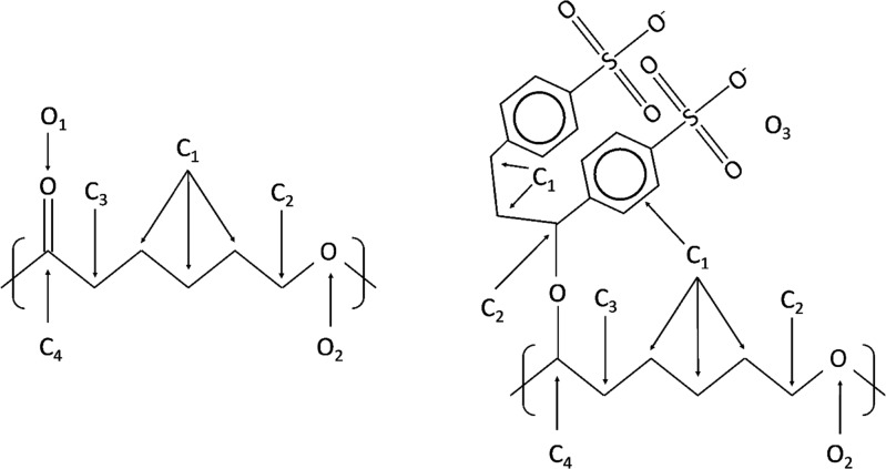
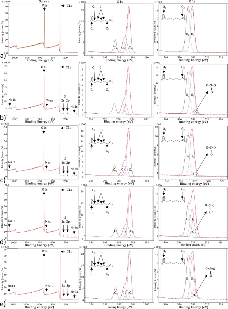
XPS analyses were performed on the different PCL fiber scaffolds following the different treatments and NaSS different grafting conditions. The assumed structure of PFSc and PFSc-polyNaSS grafted are presented in Figure 6. Each condition is made in triplicate.
Figure 6.
Untreated PFSc (left) and PFSc-polyNaSS grafted (right) formula with the different carbon and oxygen atoms assigned in XPS.
On the general spectra, Figure 7a, representing the untreated PFSc, we note the expected presence of oxygen and carbon with peaks centered at 531 and 285 eV, respectively. There is a slight difference between the theoretical atomic percentages and the observed ones, with more carbon than expected, probably due to some carbon contamination due to XPS analyses. When looking at the high-resolution XPS spectra for C1s and O1S regions, the raw data can be decomposed into four contributions and two contributions, respectively. Regarding the C1s region, the four contributions are assigned as ascribed in Figure 6, following the different chemical environments of the carbon atoms. Quantitative analyses show a good agreement between the theoretical distribution and the experimental one (Table 3), with only a small overexpression of the C1 at low binding energy (BE), again due to carbon contamination. The O1s region show two contributions assigned to both chemical forms of oxygen atoms present in the PFSc, with a very good agreement for the observed atomic percentages compared to the expected one (Figure 6 and Table 3).
Figure 7.
XPS survey spectra (left) and high-resolution spectra of the C1s (middle) and O1s (right) regions; from top to bottom: (a) ungrafted PFSc, (b) thermal grafted 1 h – Oz 20 min, (c) thermal grafted 3 h – Oz 20 min, (d) UV grafted 1 h – Oz 20 min, and (e) UV direct grafted 1 h.
Table 3. Atomic Percentages of Elements, Contributions and Total Contribution for the Different PFSc: Ungrafted and polyNaSS Grafted.
| C1s |
O1s |
Na1s | S2p |
C/O | C/S | C/O3 | O3/S | |||||||
|---|---|---|---|---|---|---|---|---|---|---|---|---|---|---|
| C1 | C2 | C3 | C4 | O3 | O1 | O2 | ||||||||
| BE (eV) | 284.9 | 285.5 | 286.2 | 289.4 | 531.6 | 532.5 | 533.7 | 1071.5 | 169.2 | 168.1 | ||||
| ungrafted PFSc | 79.3 | 20.7 | 3.8 | |||||||||||
| 55.9 | 12.9 | 15.1 | 16.1 | 50.35 | 49.65 | |||||||||
| 44.4 | 10.3 | 12.0 | 12.8 | 10.3 | 10.2 | |||||||||
| thermal grafted 1 h – Oz 20 min | 77.5 | 20.8 | 0.5 | 1.2 | 3.7 | 64.6 | 59.8 | 1.1 | ||||||
| 58.9 | 12.9 | 13.7 | 14.5 | 6.2 | 49.6 | 44.2 | ||||||||
| 45.8 | 10.0 | 10.7 | 11.2 | 1.3 | 10.3 | 9.2 | 0.5 | 0.4 | 0.8 | |||||
| thermal grafted 3 h – Oz 20 min | 76.6 | 21.5 | 0.5 | 1.4 | 3.6 | 54.7 | 70.1 | 0.8 | ||||||
| 59.8 | 13.0 | 13.6 | 13.7 | 5.2 | 51.5 | 43.7 | ||||||||
| 46.1 | 10.0 | 10.5 | 10.5 | 1.1 | 10.6 | 9.1 | 0.5 | 0.45 | 0.9 | |||||
| UV grafted 1 h – Oz 20 min | 74.8 | 20.8 | 1.1 | 3.3 | 3.6 | 22.7 | 10.5 | 2.2 | ||||||
| 60.4 | 12.7 | 15.1 | 11.8 | 32.6 | 33.3 | 34.1 | ||||||||
| 45.4 | 11.3 | 9.5 | 8.9 | 7.1 | 6.8 | 6.9 | 1.1 | 1.1 | 2.2 | |||||
| UV direct grafted 1 h | 79.2 | 20.2 | 0.2 | 0.6 | 3.9 | 132.0 | 31.2 | 4.2 | ||||||
| 57.25 | 12.3 | 15.2 | 15.25 | 12.3 | 44.3 | 43.4 | ||||||||
| 44.2 | 9.7 | 12.0 | 12.0 | 2.5 | 9.0 | 8.8 | 0.2 | 0.2 | 0.4 | |||||
| PCL −PolyNaSS theoreticala | 67.7 | 25.8 | 3.2 | 3.2 | 2.6 | 21.15 | 3.5 | 6.1 | ||||||
| 71.4 | 28.6 | 75.0 | 25.0 | |||||||||||
| 48.4 | 19.4 | 19.4 | 6.4 | 3.2 | 1.05 | 2.15 | ||||||||
| PCL theoretical | 75.0 | 25.0 | 3 | |||||||||||
| 50.0 | 16.6 | 16.6 | 16.6 | 50.0 | 50.0 | |||||||||
| 37.5 | 12.5 | 12.5 | 12.5 | 12.5 | 12.5 | |||||||||
Based on two NaSS motifs per PCL unit.
Following the polyNaSS grafting under different conditions, each survey spectrum shows the additional presence of Na1s at 1071 eV (accompanied with its corresponding Auger peak at 497 eV) and S2p at 168 eV (together with the S2s peak at around 230 eV), suggesting the successful grafting of polyNaSS onto these PFSc. The grafting is also confirmed when looking at the O1s high-resolution XPS spectra (Figure 7b–e), with the appearance of a shoulder contribution at low binding energy, 531.6 eV, assigned to O3 oxygen atoms (Figure 6).
Table 3 lists the different atomic percentages of region and contribution for these four grafted PFSc. There is a great variability in the atomic percentages of S2p according to the different PFSc series as well as on the different C/S and O/S ratios, as expected following the colorimetric assay measurements. Looking at the experimental results compared to the theoretical ones, several differences can be noticed. First of all, all atomic concentrations of Na are very low, and this can be explained by the rinsing conditions applied after grafting procedures. When looking at the atomic percentages of S2p, they are, most of the time, smaller than the expected values, except for the UV 1 h – Oz 20 min grafted sample, which almost fits the theoretical value. This is also observed for the contribution of O3 oxygen atoms with much lower observed percentages ranging from 1 to 7% as opposed to the 19.2 expected value (Table 3). These data clearly suggest that the polyNaSS grafting efficiency is not the total and it is also a function of the grafting conditions themselves.
Regarding the efficiency of polyNaSS grafting, it is clear that the surface activation step by ozone treatment is necessary to optimize the polyNaSS grafting return because, in the absence of this ozonation step, the grafting rates is minimal (PFSc UV 1 h direct grafted). Under identical conditions (thermal grafted 1 h – Oz 20 min), grafting under UV irradiation is better than thermal grafting (grafting UV 1 h – Oz 20 min vs thermal grafting 1 h – Oz 20 min, respectively). Finally, more polyNaSS is grafted after 3 h as polymerization time in thermal grafting than after 1 h (thermal grafting 3 h – Oz 20 min vs thermal grafting 1 h – Oz 20 min, respectively).
Finally, the grafting rates according to the different conditions were calculated in order to compare with the TB colorimetric measurements. For this purpose, we have estimated the grafting rates by dividing the theoretical ratios involving sulfur by the experimental ones; these values are reported in Table 4. Figure 8 shows a comparison between the XPS obtained values and those obtained by TB colorimetric assay measurements.
Table 4. PolyNaSS Grafting Rates onto PFSc for Grafting Conditions Obtained by TB Chemical Assay Measurement and XPS Calculation.
| samples | TB chemical dosing (mol/g) | %(C/S)th/(C/S)exp | %(O/S)th/(O/S)exp |
|---|---|---|---|
| ungrafted PFSc | 1.56 × 10⁻⁶ | ||
| thermal grafted 1 h – Oz 20 min | 2.14 × 10⁻⁵ | 32.7 | 46.5 |
| thermal grafted 3 h – Oz 20 min | 9.49 × 10⁻⁵ | 38.7 | 52.6 |
| UV grafted 1 h – Oz 20 min | 1.06 × 10⁻⁴ | 93.2 | 127.8 |
| UV direct grafted 1 h | 4.37 × 10⁻⁵ | 13.4 | 19.9 |
Figure 8.
Comparison between XPS obtained values and those obtained by TB colorimetric assay measurements.
There is a relatively similar trend between XPS values and chemical dosing by TB measurements, except for the UV 1 h direct grafting where XPS percentages show a lower grafting rate than thermal grafting 1 h – Oz 20 min, but this is probably due to the porous morphology of the PFSc where polyNaSS is grafted not only on the surface fibers but also on the fibers located deep in the PFSc, making these deeply grafted molecules accessible by TB chemical assay measurement but not by XPS analyses. The XPS results for the different grafted PFSc surfaces were consistent with the TB, contact anglem and FTIR-ATR results.
Effect of polyNaSS Grafting Processes on PCL Thermal Properties
Using differential scanning calorimetry (DSC), possible changes in PCL intrinsic properties (melting temperature and crystallinity degree) have been investigated. We have reproduced the four different processes of the grafting (ozonation, heating at 45 °C, and UV irradiation) without introducing the NaSS monomer to simulate the grafting steps in order to study the effect of these steps on the thermal properties of PCL independently of the presence of polyNaSS grafting itself. The thermal properties (melting temperature and crystallinity degree) of the untreated and treated PCL fiber scaffolds analyzed are listed in Table 5.
Table 5. Thermal Properties of Untreated and Treated PCL Fiber Scaffolds.
| PFSc samples | Tm (°C) | Xc (%) |
|---|---|---|
| untreated | 58 ± 0.1 | 49.7 |
| ozonated 20 min + 1 h heated at 45 °C | 61 ± 0.1 | 50.4 |
| ozonated 20 min + 3 h heated at 45 °C | 61 ± 0.6 | 49.0 |
| ozonated 20 min + UV irradiated 1 h | 61 ± 0.7 | 49.2 |
| UV irradiated 1 h | 60 ± 0.2 | 49.5 |
Untreated PFSc showed a melting temperature (Tm) of 58 °C and crystallinity degree (Xc) of 49.7% (Table 5), which is consistent with the literature.18 It was found that the grafting steps whether this is by ozonation, heating, or UV irradiation slightly increased the melting temperature. On the other hand, no significant variations in crystallinity degree occurred after the different treatments, whatever the grafting method used (thermal or UV) (Table 5). It has already been shown that the polyNaSS thermal grafting onto PCL film surfaces does not alter the thermal properties of PCL;18 however, these results remain to be confirmed with further studies on all PCL properties after the grafting process.
Evaluation of the Cell Response
Cytocompatibility, including the absence of toxicity and the good cell integration, is the key requirement for the biocompatibility of a biomaterial. The principal objective of the cell response experiments was to observe the possible differences of cell behavior on four PCL scaffolds functionalized by different techniques of grafting and exhibiting different degrees of surface hydrophilicity and compare them to each other as well as an ungrafted PCL scaffold. Fibroblast L929 cells was used to evaluate the biological response onto the PCL scaffold surfaces to appreciate the cytotoxicity, adhesion, spreading, and cell morphology.
Cytotoxicity Evaluation
MTT assay was performed as a first step of the evaluation of the cytocompatibility of the polyNaSS-grafted scaffolds (Figure 9). Cells cultured on tissue culture polystyrene (TCPS) plates were used as a reference. The ungrafted PCL scaffold exhibited 88.3 ± 4.8% cell viability; this result was expected since the PCL is a known cytocompatible polymer. PolyNaSS-grafted PCL scaffolds, for their part, showed a cell viability of >90%. The thermal grafted 3 h – Oz 20 min and UV grafted 1 h – Oz 20 min scaffolds showed the higher percentage of viability (≈93%), and the thermal grafted 1 h – Oz 20 min showed the least percentage of viable cells (91.5 ± 2.6%) among the functionalized scaffolds (Figure 9).
Figure 9.
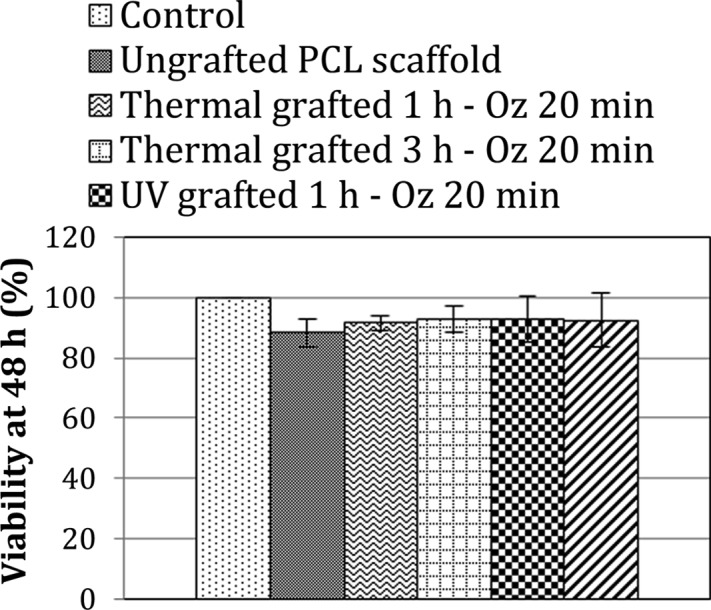
Percentage of viability of L929 fibroblast cells when seeded for 48 h onto ungrafted and different polyNaSS-grafted PCL scaffolds.
Likewise, cell viability values found for the different grafted scaffolds are quite similar; therefore, we cannot conclude that there is a difference in cell viability among the different grafted scaffolds despite the differences in polyNaSS grafting rates and surface hydrophilicity. MTT assay measurements proved the noncytotoxic nature of the polyNaSS grafting and showed instead that the polyNaSS grafting onto PCL scaffolds slightly improves the cell viability even for a short direct contact time (48 h) in the conditions tested here.
Cell Adhesion (Spreading and Morphology)
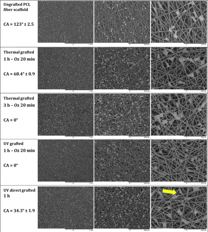
The adhesion, spreading, and morphology of L929 fibroblast cells onto ungrafted PCL scaffold and grafted PCL scaffold (thermal grafted 1 h – Oz 20 min, thermal grafted 3 h – Oz 20 min, UV grafted 1 h – Oz 20 min, and UV direct grafted 1 h) surfaces was evaluated after 4 and 7 days of culture by analyzing the SEM micrographs of scaffolds on which the cells were fixed for 30 min at 4 °C in 4% paraformaldehyde in PBS (Figures 10 and Figures 11). From the micrographs, we can observe that the cells had attached to the scaffold network at the two time points on both the ungrafted and grafted scaffolds. At day 4 (Figure 10), for the ungrafted PCL scaffold (contact angle = 123°), the cells were not well spread in comparison to the thermal grafted 1 h – Oz 20 min (contact angle = 68.4 ± 0.9°) and UV direct grafted 1 h (contact angle = 34.3 ± 1.9°) scaffolds where the cells were polygonal in shape with a well spreading and cling to the surrounding fibers at different points with the formation at some places of cytoplasmic protrusions to attach the cell to a remote fiber. The analyses of micrographs for the thermal grafted 3 h – Oz 20 min and UV grafted 1 h – Oz 20 min scaffolds, which present a contact angle of 0°, showed that the cells took a rounded shape and was not well spread onto the fibers (shape can be clearly observed at magnifications with 100 and 300 μm scale). In addition, on these two grafting conditions, the cells tend to individualize without extending their cytoplasm and thus were attached to the fibers on fewer points than for the grafted scaffolds exhibiting a contact angle greater than 0°.
Figure 10.
SEM micrographs at different magnifications of L929 fibroblast cells attached and spread onto the ungrafted PCL fiber scaffold and polyNaSS-grafted PCL fiber scaffolds taken at day 4 and contact angle values of each condition.
Figure 11.
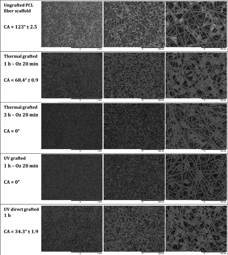
SEM micrographs at different magnifications of L929 fibroblast cells attached and spread onto ungrafted PCL scaffold and polyNaSS-grafted PCL scaffolds taken at day 7 and contact angle values of each condition.
By day 7 (Figure 11), the adherent cells have become more elongated than for the day 4 time point, and this can be explained by the fact that the cells are on scaffolds that present a three-dimensional-like structure formed by the different fiber layers superimposed on each other; therefore, the cells have taken the time to adapt to this structure quite different from a flat surface. While observing in detail the micrographs taken at day 7 (Figure 11), the first thing that can be noted is that the cells are less spread on ungrafted scaffolds compared to grafted scaffolds.
We can also observe that the cells tend to stay mostly on the surface of the ungrafted scaffold, while for the grafted scaffolds that present hydrophilic surfaces, the cells were integrated into the scaffold network and cling to fibers located on planes other than the surface. However, when grafted scaffolds are compared to each other and given the differences in the degree of hydrophilicity of the surface, we observed that the cells cultured on superhydrophilic surfaces with a contact angle of 0 ° (thermal grafted 3 h – Oz 20 min and UV grafted 1 h – Oz 20 min) were less spread and tend to become individualized, revealing uncovered scaffold spaces between cells.
On the thermal 1 h – Oz 20 min and UV direct 1 h grafted scaffolds (hydrophilic surfaces) with contact angles of 68.4 ± 0.9° and 34.3 ± 1.9°, respectively, the cells are well elongated with extensions in all directions while clinging to the fibers. They are well spread compared to cells cultured for the same time point on superhydrophilic scaffolds. Moreover, by elongating and proliferating, the cells assemble and unite to form what looks like a cellular tissue that can be clearly observed at magnifications with 300 μm scale. Therefore, the cells covered a large part of the scaffold surface for these two conditions. These outcomes at day 7 confirm those observed above at day 4.
Scaffold Surface Coverage/Distribution by Cells
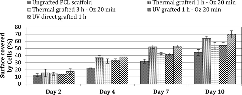
To confirm the trends revealed in the above results, cell surface coverage and distribution was appreciated by analyzing the SEM micrographs taken at different culture time points: 2, 4, 7, and 10 days. Measurements of the percentage of the surface scaffold covered by cells in relation to the total scaffold surfaces were recorded using ImageJ software. Results of distribution/coverage of cells are shown in Figure 12. As can be seen, cell coverage data over 2 days showed that the cells on both the grafted and ungrafted PCL scaffold surfaces supported steady proliferation to equivalent levels, with a slight increase observed on the various grafted scaffolds, which are consistent with the results of cytotoxicity at day 2 (Figure 12.). Indeed, since cell viability is slightly higher for the different grafted samples, the surface coverage by the cells must also be slightly higher compared to ungrafted scaffolds. Beyond day 2, the ungrafted PCL scaffolds exhibited less cell coverage than grafted scaffolds, this was not unexpected since the grafted scaffolds present a hydrophilic surface, which is known to be most suitable to support cell proliferation. Although the grafted scaffolds showed better cell coverage than ungrafted scaffolds, when compared to each other and given the substantial difference of contact angle values, we noted that scaffolds with superhydrophilic surfaces (thermal grafted 3 h – Oz 20 min “CA = 0°” and UV grafted 1 h – Oz 20 min “CA = 0°”) showed, at all time points, less cell coverage than scaffolds with a hydrophilic surface (thermal grafted 1 h – Oz 20 min “CA = 68.4°” and UV direct grafted “CA = 34.3°”) on days 4, 7, and 10. Finally, we observed, among all the grafted scaffolds, that the UV direct grafted 1 h scaffold presented slightly higher cell coverage than the others.
Figure 12.
Percentage of scaffold surface covered by L929 fibroblast cells at different time points (2, 4, 7, and 10 days).
These outcomes were consistent with expectations based on data from the cell adhesion and morphology conducted over 7 days with time points at 4 and 7 days and confirm that, as for the spreading and morphology, the grafted scaffolds with hydrophilic surfaces presented better spread cells, that is, more coverage/distribution on the scaffold surfaces since a well spreading cell will cover more surface area and the more the cells are spread the larger the area they cover on the scaffold.
To interpret these results and to be able to explain the observed effects, concerning the adhesion, spreading, and the percentage of cell coverage, we can refer to the work of Bacakova et al.40 It was revealed that the adhesion and growth of cells is optimum on materials with moderate wettability because, on these surfaces, the adhesion-mediating proteins are adsorbed in an almost physiological conformation and well recognized by the cell adhesion receptors. Specifically, it has been demonstrated that the cells adhered in higher numbers to more hydrophilic materials than hydrophobic material surfaces and were spread over a larger area. This phenomenon can be explained by the fact that the spatial conformation of the adsorbed molecules that mediate cell adhesion plays a primordial role. Furthermore, on hydrophilic surfaces, these molecules are adsorbed in a more flexible form, which allows them to be reorganized by the cells and thus provides access for cell adhesion receptors to the adhesion motifs on these molecules. However, it has been also demonstrated that a high rate of adsorbed protein could even be disadvantageous for cell adhesion due to denaturing of the proteins, and this finding is particularly important in the case of our study since we have compared the effect of not only hydrophobic and hydrophilic surfaces but also superhydrophilic surfaces, which presented a contact angle of 0°. In addition, Keselowsky et al.41 reported that an optimal cell adhesion occurs only to moderately hydrophilic surfaces. They demonstrated that, on highly hydrophilic surfaces, especially on superhydrophilic surfaces (contact angle of <2°), cell attachment and spreading are limited or completely disabled. This observation can explain why on polyNaSS-grafted scaffolds exhibiting a contact angle of 0° (thermal grafted 3 h – Oz 20 min and UV grafted 1 h – Oz 20 min), the cells were less spread and adhered to the scaffold fibers with a lower number of adhesion sites. This phenomenon is visible on the micrographs taken for these superhydrophilic surfaces, especially the UV grafted 60 min – Oz 20 min scaffold at day 4 (Figure 10). Elsewhere, previous studies carried out in our laboratory proved that the modulation of the cell behavior is as much influenced by the chemical composition of the exposed surface to binding proteins and cells as by the hydrophilic properties of the surface.18,21 Moreover, the sulfonate groups of the polyNaSS grafting can stimulate the cell adhesion and activate cell spreading as a result of the ability of the sulfonate groups to permit the modulation of the adsorption of adhesive proteins and the modulation of their conformation. As it has been shown by El Khadali et al.22 on polyNaSS-grafted biomaterial surfaces, the most important parameter is the ratio and distribution of the ionic groups in the active sites. In addition, Rohman et al.18 have reported that the grafted polyNaSS due to its negative charge provided by the location of sulfonate functions on the polyNaSS aromatic ring contributes to a better cell response for fibroblasts. It has been demonstrated that, even if the study was carried out on another PCL surface (PCL films), which differs therefrom of a flat surface compared to the PCL fiber scaffold surface, which presents a complex architecture formed by the fiber network, on a low sulfonated surface, that is, with a moderate grafting rate (and automatically a moderated hydrophilic surface character), the spreading of cells is enhanced. A hypothesis have been formulated that it is not necessary to develop PCL surfaces grafted with a high polyNaSS grafting rate in order to promote the cell response.
Outcomes of this study confirmed the results obtained previously concerning the improvement of the cell response obtained on polyNaSS grafted surfaces and demonstrate the positive effect of the grafting of polyNaSS on the fibroblastic response even on a complex architecture surface such as a biodegradable scaffold formed by a network of electrospun fibers. Moreover, we have demonstrated that a moderated grafting rate can provide suitable effects on the cell behavior.
Conclusions
The purpose of this research article was to demonstrate the feasibility of covalent grafting, under UV irradiation, a bioactive polymer onto the electrospun PCL fiber scaffold (PFSc) designed for tissue engineering applications and highlight the influence of this bioactive polyNaSS polymer on the biological response once it is grafted onto the scaffold surface.
Analyses of the PCL fiber scaffold morphology show continuous stretch of bead-free PCL fibers with uniform large pores.
The differences between four covalent “grafting from” methods are compared in terms of surface functionalization, hydrophilicity, and their effect on the in vitro biological response of fibroblasts.
The “grafting from” with surface activation gives dense and homogeneous polyNaSS grafted scaffold surfaces for both thermal (3 h) and UV initiation processes resulting in superhydrophilic surfaces. Thermal grafting 1 h with surface activation and UV direct grafting give moderated polyNaSS grafted resulting in hydrophilic surfaces. Thermal analyses demonstrated that the grafting processes did not alter the PCL intrinsic properties whatever the grafting method used.
The fibroblast biological response varied with the grafting rate and surface hydrophilicity.
Assays using L929 fibroblast cells showed no evidence of cytotoxicity when cells were in direct contact with any of the polyNaSS-grafted PFSc surfaces or the ungrafted PFSc control. It was found that better adhesion, enhanced spreading, and higher scaffold surface coverage of the fibroblast cells were shown when seeded onto the moderated grafted PCL fiber scaffolds.
The bioactive polyNaSS polymer grafted effectively modulates the fibroblast cell response when it is present in moderate amounts on PFSc surfaces.
Outcomes highlighted that the UV direct “grafting from” method, with a very easy process, allowing to moderate the amount of sulfonate groups and the surface hydrophilicity presents a considerable interest to develop bioactive and biodegradable PCL fiber scaffolds, which can be used in tissue engineering applications.
To conclude, based on the results obtained in this work, the bioactive and biodegradable PCL fiber scaffold grafted with polyNaSS could be considered in the next generation of bioactive synthetic scaffolds. The possible applications of these bioactive scaffolds, that is, covalently grafted with polyNaSS, which we are focusing on, are periodontal regeneration, spina bifida healing, and cartilage regeneration. For the last one, some experiments have started and show that the differentiation phenotype of mesenchymal cells toward chondrocytes is enhanced by the bioactive electrospun PCL fiber scaffolds. Otherwise, further studies with other cell types had to be conducted in order to accurately capture the different application fields of these potential scaffolds.
Experimental Section
Materials
All chemical products were used as received unless otherwise noted and obtained from commercial suppliers. Polycaprolactone (PCL) granules (Mn = 8 × 10⁴ g mol–1) were obtained from Sigma-Aldrich. Solvents used for the preparation of electrospinning polymer solutions were obtained from Fisher Scientific for chloroform and from Carl Roth for dimethylformamide. Distilled water was obtained from a Millipore Milli-Q Plus water purification system equipped with a 0.22 μm filter (resistivity of 18.2 MΩ cm at 25 °C). Sodium styrene sulfonate (NaSS; Sigma) used for the grafting process was purified by recrystallization in a mixture of water/ethanol (Carlo Erba) (10: 90 v/v).26,27,33,38 The purified NaSS was then dried under atmospheric pressure at 50 °C overnight and then stored at 4 °C. Fibroblast L929 cell line (mouse C3H/An adipose connective tissue) was purchased from the European Collection of Authenticated Cell Cultures (ECACC 85011425).
Electrospun PCL Fiber Scaffold (PFSc) Preparation
PCL was electrospun using a homemade electrospinning device, schematically presented in Figure 1. PCL was first dissolved in a mixture of chloroform and dimethylformamide (90/10 v/v) to prepare a 15% w/v solution and stirred overnight before use. The polymer solution was then loaded into a 10 mL glass syringe fitted with a 20 G (0.9 mm) blunt-tipped needle. The solution was continuously ejected using a syringe pump at a rate of 2 mL h–1. The voltage used for electrospinning was 9 kV, and the distance between the needle and the collector was 20 cm. The deposition time was 2 h for all experiments. PCL electrospun fiber scaffolds were dried overnight at room temperature to remove the solvent, and small disks of 16 mm ± 0.5 mm in diameter were cut after complete drying as experiment samples.
Scaffold Characterization
The fiber diameter and the morphology of the scaffold were characterized using a Hitachi TM3000 SEM. The distribution of fiber size and average fiber diameter was determined from analyzing a minimum of 50 fibers from the scaffold SEM images. The average pore size was determined by measuring a diameter of a virtual sphere between fibers in the same plan or in the nearly plan.42 All scaffold characterization measures were done using Image J software.
“Grafting from” of polyNaSS onto Electrospun PCL Fiber Scaffold Disks
Grafting with Surface Activation
For the polyNaSS grafting process after a surface activation, the first step was to suspend the samples at room temperature (30 °C) under stirring in distilled water (dH2O). With a pressure of 0.5 bar and an oxygen flow rate of 0.6 L min–1, an ozone generator BMT 802 N (ACW) allows the generation of ozone. This step creates (hydro)peroxide functions onto the PCL surface. After an ozonation step, the PCL fiber scaffold disks were transferred into a round-bottom flask containing a 0.7 M degassed aqueous solution of NaSS. The grafting was performed as follows:
-
1.
Thermal grafting: To allow the graft polymerization of NaSS, the system was maintained at 45 °C for 1 or 3 h.
-
2.
UV grafting: The activated PCL fiber scaffold disks transferred into the round-bottom flask were irradiated with UV light (365 nm with Lotoriel UV lamp) for 1 h at room temperature under stirring.
UV Direct Grafting without Surface Activation
In this grafting process, the samples were directly immersed into a round-bottom flask containing a 0.7 M degassed aqueous solution of NaSS and irradiated with UV light at room temperature under stirring. The UV device used was a Lotoriel lamp from Lot Quantum Design.38 After the polymerization process and before characterization, the grafted surfaces were rinsed for 48 h with dH2O and dried overnight at 37 °C.
Surface Characterization
The polyNaSS grafting rate onto PCL fiber scaffold surfaces was first determined using the toluidine blue (TB) colorimetric method. Then, it was characterized by water contact angle measurement (WCA), Fourier transform infrared spectra recorded in attenuated total reflection mode (ATR-FTIR), scanning electron microscopy (SEM), and X-ray photoelectron spectroscopy (XPS).
Toluidine Blue Colorimetric Method
In order to dose the polyNaSS grafting rate, TB assay (Carl Roth) was carried out onto three PCL fiber scaffold disks for each grafting. The polyNaSS-grafted disks were immersed in a TB solution (5 × 10⁻⁴ M) at 30 °C for 6 h to allow complexation of TB with the anionic groups of the grafted polymers on surfaces. It is assumed that 1 mol of toluidine blue forms a complex with 1 mol of sulfonate group.43 After incubation, the samples were washed in NaOH aqueous solution (1 × 10⁻³ M) for 5 min to remove the noncomplexed TB molecules. Decomplexation of TB was done by soaking the samples in a 10 mL mixture of acetic acid/dH2O (50/50 v/v; Fisher) for 24 h at room temperature. The concentration of decomplexed TB was measured by visible spectroscopy at 633 nm using a Perkin Elmer Lambda 25 spectrometer. Ungrafted PCL films were used as controls and found to generate low unspecific TB complexation, which was further subtracted. Three films were used per analysis. Ungrafted PCL fiber scaffold disks were used as controls and found not to react with the TB solution.
Water Contact Angle Measurements
To measure the static water contact angles onto the different PCL fiber scaffold surfaces, we used a DSA10 contact angle measuring system from KRUSS GmbH. To determine the contact angles, a droplet of water was suspended from the tip of a microliter syringe supported above the sample stage. The image of the droplet was captured, and the contact angle of dH2O (2 μL) on the surface was recorded 10 s after contact using DSA drop shape analysis software from KRUSS. Three measurements were taken and averaged.
ATR-FTIR Analyses
The Fourier transform infrared (FTIR) spectra, recorded in an attenuated total reflection (ATR), were obtained using a Perkin Elmer Spectrum Two Spectrometer. A diamond crystal (4000–500 cm–1) with a resolution of 4 cm–1 was applied. The PCL fiber scaffold disks were uniformly pressed against the crystal, and for each surface, 128 scans were acquired.
SEM Analyses
Using a scanning electron microscope (Hitachi TM3000), we analyzed the surface microtopography of the grafted PCL fiber scaffold disks (without sample preparation).
X-Ray Photoelectron Spectroscopy (XPS) Analyses
XPS analyses were performed using an Omicron Argus spectrometer (Taunusstein, Germany) equipped with a monochromated Al Kα radiation source (hν = 1486.6 eV) working at an electron beam power of 300 W. Photoelectrons emission was analyzed at a takeoff angle of 90°; the analyses were carried out under ultrahigh vacuum conditions (≤10–10 Torr) after introduction via a load-lock system into the main chamber. Spectra were obtained by setting up a 100 eV pass energy for the survey spectrum, and a pass energy of 20 eV was chosen for the high-resolution regions. Binding energies were calibrated against the C1s binding energy of aliphatic carbon atoms at 284.8 eV. Element peak intensities were corrected by Scofield factors.44 Casa XPS v.2.3.15 software (Casa Software Ltd., UK) was utilized to fit the spectra, and Gaussian/Lorentzian ratio was applied (ratio = 70/30).
Differential Scanning Calorimetry (DSC)
Differential scanning calorimetry (DSC) analysis was performed using a DSC 8000 calorimeter (PerkinElmer, Waltham, USA). Measurements were performed under a nitrogen atmosphere. PCL samples were scanned once from −80 to 100 °C at a heating and rate of 10 °C/min. Enthalpy (ΔHm) and temperature of melting (Tm) were calculated from the first and only scan using a Pyris software platform: the melting temperature was taken at the maximum of the peak, and the melting enthalpy was calculated as the melting peak area surface. The degree of crystallinity (Xc) was calculated using eq 1:
| 1 |
where ΔHm0 stands for the melting enthalpy of 100% crystalline PCL (ΔHm = 135 J g–1).45 For each scaffold condition, three samples were analyzed.
Biological Assays
PCL Scaffold Surfaces Preparation
Before the biological assays, ungrafted and grafted PCL fiber scaffold surfaces were washed consecutively under stirring at room temperature as follows: with saline aqueous solution 1.5 M sodium chloride (NaCl; Fisher), with saline aqueous solution 0.15 M NaCl, with pure water, and with phosphate-buffered saline (PBS) solution (Gibco). Each step lasts 3 h and has been repeated three times. The PCL fiber scaffolds were finally air-dried and sterilized by exposure to ultraviolet light for 15 min on each side.
Cell Seeding onto PCL Fiber Scaffold
Fibroblast L929 cells were seeded onto sterilized PCL fiber scaffolds, maintained on the bottom of individual wells of 24-well TCPS using polypropylene inserts at a density of 5 × 10⁴ cells/well, and allowed to adhere and spread. Analysis of cell association with the PCL fiber scaffolds was assessed using the following methods.
Cell Viability
Cell viability was evaluated using MTT assay.46 We used a standard cell line toxicity test to appreciate the cell viability. In this assay, we maintained a mouse fibroblast cell line L929 in DMEM (Sigma-Aldrich) containing 10% FBS, l-glutamine, penicillin, and streptomycin at 37 °C in humidified air containing 5% CO2. The mitochondrial dehydrogenases of viable cells cleave the yellow (3-(4,5-dimethylthiazol-2-yl)-2,5-diphenyltetrazolium bromide) (MTT, Sigma) substrate to produce purple formazan crystals. After 48 h incubation of cells within the scaffolds, 50 μL of a freshly prepared MTT solution (5 mg/mL) was added to each well and incubated for 2 h at 37 °C. Cell media was then discarded, and 0.5 mL of dimethyl sulfoxide was used to dissolve the formazan crystals. As a control, we used cells treated with MTT without scaffold. The absorbance was measured at 570 nm47 using a microplate reader (ELx800, BioTek). Mitochondrial activity as an indicator of cell viability was calculated as the absorbance ratio between cells cultured within scaffolds and nontreated cells (blank).
Cell Morphology
The morphology of L929 fibroblasts onto the control PCL fiber scaffold and polyNaSS-grafted PCL fiber scaffolds was studied at 2 and 7 days (n = 2 for each condition at each time point). In this assay, the ungrafted or polyNaSS-grafted PCL fiber scaffold disks are placed on the bottom of individual wells of 24-well TCPS plate and maintained using Teflon inserts. Cells were seeded onto samples at a density of 5 × 10⁴ cells/well and allowed to adhere and spread to two time points (2 and 7 days). After these time periods, the medium was removed, and samples were rinsed twice with phosphate-buffered serum (PBS) then fixed for 30 min at 4 °C in 4% paraformaldehyde in PBS, washed twice with PBS, and finally once with ultrapure water for 5 min. The samples were stored at 4 °C overnight before observation. Cell morphology and spreading was evaluated from the SEM images using SEM (Hitachi TM3000).
Scaffold Surface Coverage/Distribution by Cells
Scaffold surface coverage by cells was evaluated by analyzing the SEM micrographs of scaffold surfaces seeded by L929 fibroblast cells. Cell seeding and fixation was performed according to the same protocol as the cell morphology study. In this assay, the cells were cultured onto scaffolds for time points: 2, 4, 7, and 10 days. From the SEM micrographs taken at different time points, the calculation of the percentage of the surface scaffold covered by cells in relation to the total scaffold surface was recorded using ImageJ software (n = 3 for each condition at each time point).
Acknowledgments
This research was supported by the French Ministry of National Education, Higher Education and Research. The authors acknowledge IMPC (Institut des Matériaux de Paris Centre, FR CNRS 2482) and the C’Nano projects of the Region Ile-de-France, Omicron XPS apparatus funding.
Author Contributions
G.A. as Ph.D. student was in charge of the following experiments: electrospinning (production of PCL fiber scaffolds), chemistry, physicochemistry (FTIR, SEM, TB, and contact angle), and cell response study: cell culture, imaging, and analysis. C.F.-D. initiated G.A. to the grafting from and to processes (electrospinning and physicochemistry (FTIR, SEM, TB, contact angle)). C.F.-D. was in charge of all the DSC characterization experiments and analyses. Except for the cell response assays and the XPS characterization, the experiments were completed at the LBPS/CSPBAT UMR CNRS 7244, University Paris 13, Villetaneuse, France. V.H. was in charge of all the XPS characterization experiments and analyses completed at the Sorbonne Université, Laboratoire de Réactivité de Surface, UMR CNRS 7197, 4 place Jussieu, 75252 Paris cedex 05, France. E.J. and N.Y. initiated G.A. and allowed him to carry out the cell response assays at the Laboratoire Matériaux et Santé EA 401, UFR de Pharmacie, Université Paris-Sud, 92290 Châtenay-Malabry, France. C.F.-D., S. R., and V.M. as the supervisors of the Ph.D. program of G.A. set up the study program and analyzed the whole results. The manuscript was written through contributions of all authors.
The authors declare no competing financial interest.
References
- Shahhosseininia M.; Bazgirb S.; Joupari M. D. Fabrication and investigation of silica nanofibers via electrospinning. Mater. Sci. Eng. C 2018, 91, 502–511. 10.1016/j.msec.2018.05.068. [DOI] [PubMed] [Google Scholar]
- Chenga H.; Yanga X.; Cheb X.; Yangb M.; Zhaia G. Biomedical application and controlled drug release of electrospun fibrous materials. Mater. Sci. Eng. C 2018, 90, 750–763. 10.1016/j.msec.2018.05.007. [DOI] [PubMed] [Google Scholar]
- Zamani M.; Prabhakaran M. P.; Ramakrishna S. Advances in drug delivery via electrospun and electrosprayed nanomaterials. Int. J. Nanomed. 2013, 2997–3017. 10.2147/IJN.S43575. [DOI] [PMC free article] [PubMed] [Google Scholar]
- Annis D.; Bornat A.; Edwards R. O.; Higham A.; Loveday B.; Wilson J. An elastomeric vascular prosthesis. Trans. - Am. Soc. Artif. Intern. Organs 1978, 24, 209–214. [PubMed] [Google Scholar]
- Tallawi M.; Dippold D.; Rai R.; D’Atri D.; Roether J. A.; Schubert D. W.; Rosellini E.; Engel F. B.; Boccaccini A. R. Novel PGS/PCL electrospun fiber mats with patterned topographical features for cardiac patch applications. Mater. Sci. Eng. C 2016, 69, 569–576. 10.1016/j.msec.2016.06.083. [DOI] [PubMed] [Google Scholar]
- Yoo H. S.; Kim T. G.; Park T. G. Surface-functionalized electrospun nanofibers for tissue engineering and drug delivery. Adv. Drug Delivery Rev. 2009, 61, 1033–1042. 10.1016/j.addr.2009.07.007. [DOI] [PubMed] [Google Scholar]
- Kai D.; Ren W.; Tian L.; Chee P. L.; Liu Y.; Ramakrishna S.; Loh X. J. Engineering poly(lactide)–lignin nanofibers with antioxidant activity for biomedical application. ACS Sustainable Chem. Eng. 2016, 4, 5268–5276. 10.1021/acssuschemeng.6b00478. [DOI] [Google Scholar]
- Holzwarth J. M.; Ma P. X. Biomimetic nanofibrous scaffolds for bone tissue engineering. Biomaterials 2011, 32, 9622–9629. 10.1016/j.biomaterials.2011.09.009. [DOI] [PMC free article] [PubMed] [Google Scholar]
- Kai D.; Prabhakaran M. P.; Chan B. Q. Y.; Liow S. S.; Ramakrishna S.; Xu F.; Loh X. J. Elastic poly(ε-caprolactone)-polydimethylsiloxane copolymer fibers with shape memory effect for bone tissue engineering. Biomed. Mater. 2016, 11, 015007 10.1088/1748-6041/11/1/015007. [DOI] [PubMed] [Google Scholar]
- Hayami J. W. S.; Surrao D. C.; Waldman S. D.; Amsden B. G. Design and characterization of a biodegradable composite scaffold for ligament tissue engineering. J. Biomed. Mater. Res., Part A 2010, 92, 1407–1420. 10.1016/j.msec.2018.05.068. [DOI] [PubMed] [Google Scholar]
- Kai D.; Tan M. J.; Prabhakaran M. P.; Chan B. Q. Y.; Liow S. S.; Ramakrishna S.; Loh X. J. Biocompatible electrically conductive nanofibers from inorganic-organic shape memory polymers. Colloids Surf., B 2016, 148, 557–565. 10.1016/j.colsurfb.2016.09.035. [DOI] [PubMed] [Google Scholar]
- Hu J.; Kai D.; Ye H.; Tian L.; Ding X.; Ramakrishna S.; Loh X. J. Electrospinning of poly(glycerol sebacate)-based nanofibers for nerve tissue engineering. Mater. Sci. Eng.: C 2017, 70, 1089–1094. 10.1016/j.msec.2016.03.035. [DOI] [PubMed] [Google Scholar]
- Entekhabi E.; Nazarpak M. H.; Moztarzadeh F.; Sadeghi A. Design and manufacture of neural tissue engineering scaffolds using hyaluronic acid and polycaprolactone nanofibers with controlled porosity. Mater. Sci. Eng.: C 2016, 69, 380–387. 10.1016/j.msec.2016.06.078. [DOI] [PubMed] [Google Scholar]
- Chen H.; Huang J.; Yu J.; Liu S.; Gu P. Electrospun chitosan-graft-poly (ε-caprolactone)/poly (ε-caprolactone) cationic nanofibrous mats as potential scaffolds for skin tissue engineering. Int. J. Biol. Macromol. 2011, 48, 13–19. 10.1016/j.ijbiomac.2010.09.019. [DOI] [PubMed] [Google Scholar]
- Goddard J. M.; Hotchkiss J. H. Polymer surface modification for the attachment of bioactive compounds. Prog. Polym. Sci. 2007, 32, 698–725. 10.1016/j.progpolymsci.2007.04.002. [DOI] [Google Scholar]
- Lin C.-L.; Chang M.-C.; Hung S.-C.; Lee S.-Y.; Lin Y.-M. Bioactive surface modification of polycaprolactone using MG63-conditioned medium can induce osteogenic differentiation of mesenchymal stem cells. J. Mater. Sci. 2017, 52, 3967–3978. 10.1007/s10853-016-0659-0. [DOI] [Google Scholar]
- Huot S.; Rohman G.; Riffault M.; Pinzano A.; Grossin L.; Migonney V. Increasing the bioactivity of elastomeric poly(ε-caprolactone) scaffolds for use in tissue engineering. Bio-Med. Mater. Eng. 2013, 23, 281–288. 10.3233/BME-130752. [DOI] [PubMed] [Google Scholar]
- Rohman G.; Huot S.; Vilas-Boas M.; Radu-Bostan G.; Castner D. G.; Migonney V. The grafting of a thin layer of poly(sodium styrene sulfonate) onto poly(e-caprolactone) surface can enhance fibroblast behavior. J. Mater. Sci.: Mater. Med. 2015, 26, 206. [DOI] [PMC free article] [PubMed] [Google Scholar]
- Leroux A.; Egles C.; Migonney V. Impact of chemical and physical treatments on the mechanical properties of poly(ε-caprolactone) fibers bundles for the anterior cruciate ligament reconstruction. PLoSONE 2018, 13, e0205722 10.1371/journal.pone.0205722. [DOI] [PMC free article] [PubMed] [Google Scholar]
- Leroux A.; Maurice E.; Viateau V.; Migonney V. Feasibility Study of the Elaboration of a Biodegradable and Bioactive Ligament Made of Poly(ε-caprolactone)-pNaSS Grafted Fibers for the Reconstruction of Anterior Cruciate Ligament: In Vivo Experiment. IRBM 2019, 40, 38–44. 10.1016/j.irbm.2018.10.011. [DOI] [Google Scholar]
- Venkatesan J. K.; Leroux A.; Baumann J.-S.; Rey-Rico A.; Falentin-Daudré C.; Frisch J.; Madry H.; Migonney V.; Cucchiarini M. Genetic modification of human bone marrow aspirates via delivery of rAAV vectors coated on pNaSS-grafted poly(ε-caprolactone) scaffolds. Osteoarthritis and Cartilage 2018, 26, 134–135. 10.1016/j.joca.2018.02.291. [DOI] [Google Scholar]
- El Khadali F.; Hélary G.; Pavon-Djavid G.; Migonney V. Modulating fibroblast cell proliferation with functionalized poly (methyl methacrylate) based copolymers: chemical composition and monomer distribution effect. Biomacromolecules 2002, 3, 51–56. 10.1021/bm015563x. [DOI] [PubMed] [Google Scholar]
- Anagnostou F.; Debet F.; Pavon-Djavid G.; Goudaby Z.; Hélary G.; Migonney V. Osteoblast functions on functionalized PMMA-based polymers exhibiting Staphylococcus aureus adhesion inhibition. Biomaterials 2006, 27, 3912–3919. 10.1016/j.biomaterials.2006.03.004. [DOI] [PubMed] [Google Scholar]
- Poussard L.; Ouédraogo C. P.; Pavon-Djavid G.; Migonney V. Inhibition of Staphylococcus epidermidis adhesion on titanium surface with bioactive water-soluble copolymers bearing sulfonate, phosphate or carboxylate functions. Pathol. Biol. 2012, 60, 84–90. 10.1016/j.patbio.2010.07.004. [DOI] [PubMed] [Google Scholar]
- Migonney V.; Hélary G.; Noirclere F.. Method for grafting bioactive polymers on prosthetic materials. WO patent 2007/141460 A3, 2006.
- Amokrane G.; Hocini A.; Ameyama K.; Dirras G.; Migonney V.; Falentin-Daudre C. Functionalization of New Biocompatible Titanium Alloys with Harmonic Structure Design by Using UV Irradiation. IRBM 2017, 38, 190–197. 10.1016/j.irbm.2017.06.008. [DOI] [Google Scholar]
- Chouirfa H.; Migonney V.; Falentin-Daudré C. Grafting bioactive polymers onto titanium implants by UV irradiation. RSC Adv. 2016, 6, 13766–13771. 10.1039/C5RA24497H. [DOI] [Google Scholar]
- Chouirfa H.; Evans M. D. M.; Bean P.; Saleh-Mghir S.; Crémieux A. C.; Castner D. G.; Falentin-Daudré C.; Migonney V. Grafting of Bioactive Polymers with Various Architectures: A Versatile Tool for Preparing Antibacterial Infection and Biocompatible Surfaces. ACS Appl. Mater. Interfaces 2018, 10, 1480–1491. 10.1021/acsami.7b14283. [DOI] [PMC free article] [PubMed] [Google Scholar]
- Hélary G.; Noirclére F.; Mayingi J.; Migonney V. A new approach to graft bioactive polymer on titanium implants: Improvement of MG 63 cell differentiation onto this coating. Acta Biomater. 2009, 5, 124–133. 10.1016/j.actbio.2008.07.037. [DOI] [PubMed] [Google Scholar]
- Hélary G.; Noirclére F.; Mayingi J.; Bacroix B.; Migonney V. A bioactive polymer grafted on titanium oxide layer obtained by electrochemical oxidation. Improvement of cell response. J. Mater. Sci.: Mater. Med. 2010, 21, 655–663. 10.1007/s10856-009-3892-0. [DOI] [PubMed] [Google Scholar]
- Felgueiras H.; Migonney V. Sulfonate groups grafted on Ti6Al4V favor MC3T3-E1 cell performance in serum free medium conditions. Mater. Sci. Eng. C. 2014, 39, 196–202. 10.1016/j.msec.2014.03.013. [DOI] [PubMed] [Google Scholar]
- Vasconcelos D. M.; Falentin-Daudré C.; Blanquaert D.; Thomas D.; Granja P. L.; Migonney V. Role of protein environment and bioactive polymer grafting in the S. epidermidis response to titanium alloy for biomedical applications. Mater. Sci. Eng. C. 2014, 45, 176–183. 10.1016/j.msec.2014.08.054. [DOI] [PubMed] [Google Scholar]
- Falentin-Daudre C.; Migonney V.; Chouirfa H.; Baumann J. S.. Procédé de greffage de polymères bioactifs sur des matériaux métalliques. FR patent, 15 57621, 2015. (Extension PCT submitted: 8 aôt 2016, n° PCT/EP2016/068909).
- Felgueiras H. P.; Ben Aissa I.; Evans M. D. M.; Migonney V. Contributions of adhesive proteins to the cellular and bacterial response to surfaces treated with bioactive polymers: case of poly(sodium styrene sulfonate) grafted titanium surfaces. J. Mater. Sci.: Mater. Med. 2015, 26, 261. 10.1007/s10856-015-5596-y. [DOI] [PubMed] [Google Scholar]
- Pavon-Djavid G.; Gamble L. J.; Ciobanu M.; Gueguen V.; Castner D. G.; Migonney V. Bioactive Poly(ethylene terephthalate) Fibers and Fabrics: Grafting, Chemical Characterization, and Biological Assessment. Biomacromolecules 2007, 8, 3317–3325. [DOI] [PubMed] [Google Scholar]
- Viateau V.; Zhou J.; Guérard S.; Manassero M.; Thourot M.; Anagnostou F.; Mitton D.; Brulez B.; Migonney V. Ligart: Synthetic ≪ bioactive ≫ and ≪ biointegrable ≫ ligament allowing a rapid recovery of patients: chemical grafting, in vitro and in vivo biological evaluation, animal experiments, preclinical study. IRBM 2011, 32, 118–122. 10.1016/j.irbm.2011.01.007. [DOI] [Google Scholar]
- Vaquette C.; Viateau V.; Guérard S.; Anagnostou F.; Manassero M.; Castner D. G.; Migonney V. The effect of polystyrene sodium sulfonate grafting on polyethylene terephthalate artificial ligaments on in vitro mineralisation and in vivo bone tissue integration. Biomaterials 2013, 34, 7048–7063. 10.1016/j.biomaterials.2013.05.058. [DOI] [PMC free article] [PubMed] [Google Scholar]
- Amokrane G.; Falentin-daudré C.; Ramtani S.; Migonney V. A simple method to functionalize PCL surface by grafting bioactive polymers using UV irradiation. IRBM 2018, 39, 268–278. 10.1016/j.irbm.2018.07.002. [DOI] [Google Scholar]
- Sunandhakumari V. J.; Vidhyadharan A. K.; Alim A.; Kumar D.; Ravindran J.; Krishna A.; Prasad M. Fabrication and In Vitro Characterization of Bioactive Glass/Nano Hydroxyapatite Reinforced Electrospun Poly(ε-Caprolactone) Composite Membranes for Guided Tissue Regeneration. Bioengineering 2018, 5, 54. 10.3390/bioengineering5030054. [DOI] [PMC free article] [PubMed] [Google Scholar]
- Bacakova L.; Filova E.; Parizek M.; Ruml T.; Svorcik V. Modulation of cell adhesion, proliferation and differentiation on materials designed for body implants. Biotechnol. Adv. 2011, 29, 739–767. 10.1016/j.biotechadv.2011.06.004. [DOI] [PubMed] [Google Scholar]
- Keselowsky B. G.; Collard D. M.; Garcìa A. J. Surface chemistry modulates fibronectin conformation and directs integrin binding and specificity to control cell adhesion. J. Biomed. Mater. Res., Part A 2003, 66, 247–259. 10.1002/jbm.a.10537. [DOI] [PubMed] [Google Scholar]
- Vaquette C.; Cooper-White J. J. Increasing electrospun scaffold pore size with tailored collectors for improved cell penetration. Acta Biomater. 2011, 7, 2544–2557. 10.1016/j.actbio.2011.02.036. [DOI] [PubMed] [Google Scholar]
- Kato K.; Ikada Y. Selective adsorption of proteins to their ligands covalently immobilized onto microfibers. Biotechnol. Bioeng. 1995, 47, 557–566. 10.1002/bit.260470508. [DOI] [PubMed] [Google Scholar]
- Scofield J. H. Hartree-Slater Subshell Photoionization Cross-Sections at 1254 and 1487 eV. J. Electron Spectrosc. Relat. Phenom. 1976, 8, 129–137. 10.1016/0368-2048(76)80015-1. [DOI] [Google Scholar]
- Kweon H.; Yoo M. K.; Park I. K.; Kim T. H.; Lee H. C.; Lee H.-S.; Oh J.-S.; Akaike T.; Cho C.-S. A novel degradable polycaprolactone networks for tissue engineering. Biomaterials 2003, 24, 801–808. 10.1016/S0142-9612(02)00370-8. [DOI] [PubMed] [Google Scholar]
- Manokawinchoke J.; Nattasit P.; Thongngam T.; Pavasant P.; Tompkins K. A.; Egusa H.; Osathanon T. RNA sequencing data of Notch ligand treated human dental pulp cells. Data in Brief 2018, 17, 407–413. 10.1016/j.dib.2018.01.058. [DOI] [PMC free article] [PubMed] [Google Scholar]
- Nowwarote N.; Chanjavanakul P.; Kongdecha P.; Clayhan P.; Chumprasert S.; Manokawinchoke J.; Egusa H.; Pavasant P.; Osathanon T. Characterization of a bioactive Jagged1-coated polycaprolactone-based membrane for guided tissue regeneration. Arch. Oral Biol. 2018, 88, 24–33. 10.1016/j.archoralbio.2018.01.007. [DOI] [PubMed] [Google Scholar]


