Abstract
This paper presents a new robotic navigation aid, called Co-Robotic Cane (CRC). The CRC uses a 3D camera for both pose estimation and object recognition in an unknown indoor environment. The 6-DOF pose estimation method determines the CRC’s pose change by an egomotion estimation method and the iterative closest point algorithm and reduces the pose integration error by a pose graph optimization algorithm. The pose estimation method does not require any prior knowledge of the environment. The object recognition method detects indoor structures such as stairways, doorways, etc. and objects such as tables, computer monitors, etc. by a Gaussian Mixture Model based pattern recognition method. Some structures/objects (e.g., stairways) can be used as navigational waypoints and the others for obstacle avoidance. The CRC can be used in either robot cane (active) mode or white cane (passive) mode. In the active mode it guides the user by steering itself into the desired direction of travel, while in the passive mode it functions as a computer-vision-enhanced white cane. The CRC is a co-robot. It can detect human intent and use the intent to select a suitable mode automatically.
Keywords: robotic navigation aid, co-robot, human-robot interaction, pose estimation, egomotion estimation, pose graph optimization, 3D object recognition
I. Introduction
According to the World Health Organization, about 285 million people worldwide are visually impaired, of which 39 million are blind. Visual impairment degrades one’s independent mobility and deteriorates the quality of life. In the visually impaired community, white canes are currently the most efficient and widely-used mobility tools. A white cane provides haptic feedback for obstacle avoidance. However, it cannot provide necessary information for wayfinding—taking a path towards the destination with awareness of position and orientation. Also, as a point-contact device a white cane has a limited range and cannot provide a “full picture” of its surrounding. To address these limitations, Robotic Navigation Aids (RNAs) have been introduced to replace/enhance white canes. But only limited success has been achieved. Up to date, there is no RNA that has effectively addressed both the obstacle avoidance and wayfinding problems. The main technical challenge is that both problems must be addressed inside a small platform with limited resources.
Existing RNAs can be classified into three categories: robotic wheelchair [1], Robotic Guide-Dog (RGD) [2, 3] and Electronic White Cane (EWC) [4, 5, 6]. A robotic wheelchair is well suited for a blind person with disability in lower extremity. However, it gives its user an unpleasant sense of being controlled. Safety concerns will keep the blind away from using robotic wheelchairs for their mobility needs. An RGD leads the blind user along a walkable direction towards the destination. In this case, the user walks by himself/herself. An RGD can be passive or active. A passive RGD [2] indicates the desired travel direction by steering the wheels and the user pushes the RGD forward. A passive RG gives its user the sense that they are controlling the device but requires extra workload that might cause fatigue to the user. An active RGD [3], however, generates an additional forward movement to lead the user to the destination. Therefore, it can take on a certain payload and does not require the user to push, causing no fatigue to the user. However, the robot-centric motion may cause safety concerns. In addition to the abovementioned disadvantages, both robotic wheelchairs and RGDs lack portability. This issue makes EWC an appealing solution. An EWC is a handheld device that detects obstacle(s) in its vicinity. The Nottingham obstacle detector [4] uses a sonar for obstacle detection. The C-5 laser cane [5] triangulates range using three pairs of laser-/photo-diodes. The “virtual white cane” [6] measures obstacle distance by a triangulation system comprising a laser pointer and a camera. The user receives multiple range measurements by swinging an EWC. In spite of the portability, these EWCs: (1) provide only limited obstacle information due to the restricted sensing capability; (2) do not provide location information for wayfinding; and (3) may limit or deny the use of a white cane.
With respect to wayfinding, GPS has been widely used in portable navigation aids for the visually impaired [7, 8]. However, the approach cannot be used in GPS-denied indoor environments. To address this problem and the third disadvantage of the EWCs, a portable indoor localization aid is introduced in [9], where a sensor package, comprising an Inertial Measurement Unit (IMU) and a 2D laser scanner, is mounted on a white cane for device pose estimation. An extended Kalman filter is employed to predict the device’s pose from the data of the IMU and a user-worn pedometer and update the prediction using the laser scans (observation). The pose estimation method requires a map of the environment that must be vertical in order to predict laser measurements.
In [10], we conceive a new RNA, called Co-Robotic Cane (CRC), for indoor navigation for a blind person. The CRC uses a 3D camera for both pose estimation and object recognition in an unknown indoor environment. The pose estimation method does not require any prior knowledge of the environment. The object recognition method detects indoor structures and objects, some of which may be used as navigational waypoints. The CRC is a co-robot. It can detect human intent and use the intent to automatically select its use mode. Recently, we designed and fabricated the CRC. This paper presents the three key technology components—human intent detection, pose estimation and 3D object recognition—and the fabrication of the CRC. It is an extended version of [10].
II. Overview of Co-robotic Cane
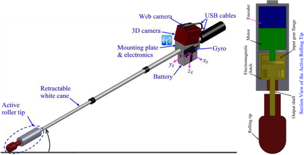
The conceptual CRC is an indoor navigation aid as depicted in Fig. 1. The CRC is a computer-vision-enhanced white cane that allows a blind traveler to “see” better and farther. It provides the user the desired travel direction in an intuitive way and offers a friendly human-device interface. The computer vision system, comprising a 3D camera, a 3-axis gyro and a Gumstix Overo® AirSTORM COM computer, provides both pose estimation and object recognition functions. The CRC’s pose is used to provide the user with location information and to register the camera’s 3D points into a 3D map. The Gumstix reads data from the camera and gyro and relays the data via WiFi to a backend computer for pose estimation and object recognition computation. The results are sent back to the Gumstix for navigation. This arrangement is due to the Gumstix’s limited computing power and intended to save power. The CRC has an active rolling tip that can steer itself to the desired direction of travel. A speech interface using a Bluetooth headset and a keypad (on the cane’s grip) is being developed for human-device interaction.
Fig. 1.
The Co-Robotic Cane
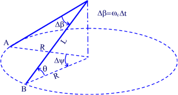
The CRC has two navigation modes—robot cane (active) mode and white cane (passive) mode—that are selectable to the user by controlling the so-called Active Rolling Tip (ART). The ART comprises a rolling tip, a servo motor assembly with an encoder and an electromagnetic clutch. The rolling tip is connected to the motor through the clutch. A disengaged clutch sets the CRC to its passive mode. In this mode, the rolling tip rotates freely just like a conventional white cane when the user swings the CRC. In this case, the speech interface provides the desired travel direction and object/obstacle information to the user. An engaged clutch sets the CRC to the active mode, allowing the motor to drive the rolling tip and steer the CRC to the desired direction of travel. The CRC is a robot in this mode. Assuming that the CRC is swung from A to B with no slip (see Fig. 2), the yaw angle change of the device is Δψ = Δαr/CLcosθ, where Δα is the motor’s rotation angle, C is the gearhead reduction ratio, r is the rolling tip’s radius, and L is the cane’s length. This means that the cane’s turn angle can be accurately controlled by the motor.
Fig. 2.
The CRC Swings from A to B
Mode selection is made by using the keypad or an intuitive Human Intent Detection Interface (HIDI). The HIDI measures the user’s compliance with the cane’s motion by analyzing the data from the encoder and the 3-axis gyro (see Fig. 1). When the user is compliant with the cane’s motion, the CRC’s gyro-measured angular velocity ωg must agree with its encoder-measured angular velocity ωc = rΔα/CLΔt cosθ. If the user swings the cane in the active mode, substantial slip at the rolling tip will be produced. The slip is given by S = ωc − ωg. If S is above a threshold, a motion-incompliance, indicating the user’s intent of using the CRC in the passive mode, is then detected and the CRC is switched to the passive mode. The CRC is switched back to the active mode once a motion-compliance is detected. The HIDI also detects motion-incompliance when the roller tip slips on a loose ground due to insufficient traction. This indicates that it is unsuitable to use the active mode. In this case, the CRC also switches itself into the passive mode until sufficient traction is produced. The user may override the auto-switch function by manually selecting a mode through the keypad.
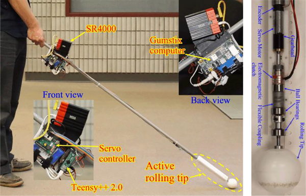
Fig. 3 depicts the first CRC prototype we have fabricated. A SwissRanger SR4000 is used for 3D perception. The ART (bottom image) is an assembly of motor, encoder, gear head and electromagnetic clutch that is connected to a ball-bearing-supported rolling tip by a flexible coupling. A servo controller and a microcontroller boards (Teensy++ 2.0) are used to control the motor and the clutch, respectively. Both controller boards are connected to the Gumstix’s USB ports. An IMU is used to measure the cane rotation rate. Using ground truth rotation provided by a motion capture system, we found that the maximum S value with no slip is ~1°/s. So we simply use 2°/s as threshold for determining motion compliance. Since the S value is much bigger than 2°/s when the user swings the cane at the active mode, the threshold results in a reliable detection of motion compliance. This has been validated by experiments. With the current design, the CRC’s maximum rotational (yaw) speed is 30°/s in the active mode. We tested the CRC on the grounds in a few buildings on campus. With this maximum speed, S<2°/s (no slip produced). Currently, the CRC’s weight is close to 1 kg. The majority of the weight (0.7 kg) is located at 20 cm from the center of the hand grip to make it easy to swing the cane. Our test reveals that no discomfort is produced when the CRC user swings the CRC back and forth. The CRC weight may be reduced if a lighter camera will be used.
Fig. 3.
The first CRC prototype and the active rolling tip
III. 3D Camera—SwissRanger SR4000
The SR4000 is a small-sized (65×65×68 mm3) 3D time-of-flight camera. It illuminates the environment with modulated infrared light and measures ranges up to 5 meters (accuracy: ±1 cm, resolution: 176×144) using phase shift measurement. The camera produces range, intensity and confidence data at a rate up to 54 frames/s. The SR4000 has a much better range measurement accuracy for distant object and data completeness than a stereo/RGB-D camera (e.g., Microsoft Kinect). This may result in better pose estimation and object recognition performances. In addition, the camera has a smaller dimension that makes it suitable for the CRC.
IV. 6-DOF Pose Estimation
A. Egomotion Estimation
The camera’s pose change between two views is determined by an egomtion estimation method, called Visual Range Odometry (VRO) [11] and the Iterative Closest Point (ICP) algorithm. The VRO method extracts and matches the SIFT features [12] in two consecutive intensity images. As the features’ 3D coordinates are known from the depth data, the feature tracking process results in two associated 3D point sets, {pi} and {qi}. The rotation and translation matrices, R and T, between the two point sets can be determined by minimizing the error residual:
| (1) |
where N is the number of the matched SIFT features. This least-squares data fitting problem is solved by the Singular Value Decomposition method [13]. As SIFT feature matching may produce incorrect feature correspondences (outliers), a RANSAC process is used to reject the outliers. The resulted inliers are then used to estimate R and T, from which the camera’s pose change is determined. In this paper, the camera pose is described by the X, Y, Z coordinates and Euler angles (yaw-pitch-roll angles). To estimate pose change more accurately, a Gaussian filter is used to reduce the noises of the intensity and range data and SIFT features with low confidence are discarded [14] for VRO computation. To overcome the VRO’s performance degradation in a visual-feature-spare environment (e.g. an open area with texture-less floor), an ICP-based shape tracker is devised to refine the alignment of the two point sets and thus the camera’s pose change. In this work, a convex hall is created using the 3D points of the matched SIFT features. The 3D data points within the convex hall are used for ICP calculation. This scheme substantially reduces the computational time of a standard ICP process that uses all data points. The proposed egomotion estimation method is termed VRO-FICP [15].
B. Pose Error Minimization by Pose Graph Optimization
Visual feature tracking by state estimation filter such as the Extended Kalman Filtering (EKF) and Pose Graph Optimization (PGO) methods have been proposed to reduce the accumulative pose error of the dead reckoning approach. Our recent study [16] shows that a PGO method has a better performance consistency than an EKF. Therefore, we use PGO to minimize the pose error in this paper.
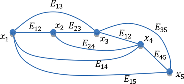
Let x = (x1,…,xN)T be a vector consisting of nodes x1,…,xN, where xi for i=1, …, N, is the SR4000’s pose at time step i (i.e., image frame i). Let zij and Ωij be the mean and information matrix of a virtual measurement between nodes i and j. Let be the expected value of zij. The measurement error and Ωij are used to describe the edge connecting nodes i and j. Fig. 4 shows a pose graph with 5 nodes.
Fig. 4.
A pose graph with five nodes: Eij =< eij,Ωij > represents the edge between nodes i and j.
A number of approaches are taken to ensure a quality graph for PGO. When adding node xi to the graph, z(i−1)i (i.e., pose change between i and j) may be unavailable if VRO-FICP fails. In this case, we assume a constant movement and use z(i−2)(i−1) to create node xi, i.e., e(i−2)(i−1) and Ω(i−2)(i−1) are used for edge E(i−1)i. For non-consecutive nodes, no edge is created if VRO-FICP fails or the pose change uncertainties are large. We use the following bootstrap method to compute pose change uncertainties: (1) Compute a pose change using K = min(0.75N, 40) samples randomly drawn from the N correspondences given by VRO-FICP; (2) Compute 50 pose changes by repeating step (1) and calculate the standard deviation. Finally, Ωij is computed as the inverse of the diagonal matrix of the pose change uncertainties. Compared with the existing works that assume a constant uncertainty in graph construction, our method may result in a more accurate graph and thus improves the pose estimation result.
The PGO process is to find the node-configuration x* that minimizes the following nonlinear cost function:
| (2) |
A numerical approach based on the Levenberg-Marquardt algorithm is used to solve the optimization problem iteratively. Details on the PGO method are referred to [17]. In this paper, we use the GTSAM C++ library [18] for PGO. The VRO-FICP based approach substantially improves the pose estimation accuracy of the VRO-based method and reduces the computational time of the VRO-ICP-based method. Readers are referred to [15] for more details.
V. 3D Object Recognition
Object recognition is important to wayfinding. Objects detected by the CRC can be used: (1) as waypoints for navigation, (2) for environment awareness (e.g. in an office, hallway, etc.), and (3) for obstacle avoidance. A detected stairway may be used as a waypoint to access the next floor and a doorway a waypoint to enter/exit a room. Detection of a hallway may assist the CRC user with moving direction. Five objects (doorway, hallway, stairway, ground and wall) representing indoor structures and three objects (monitor, table, parallelepiped) related to office environment are considered in this paper. It is noted that the parallelepiped is not yet associated with an office object yet. But it can be a computer case if the relevant data are used to train the detector. As most of the target objects are indoor structures, their determining factors are geometric features rather than visual features. For example, a stairway contains a group of alternating treads and risers with a fixed size while its visual appearance can be various. Therefore, a geometric feature based object recognition method becomes appropriate.
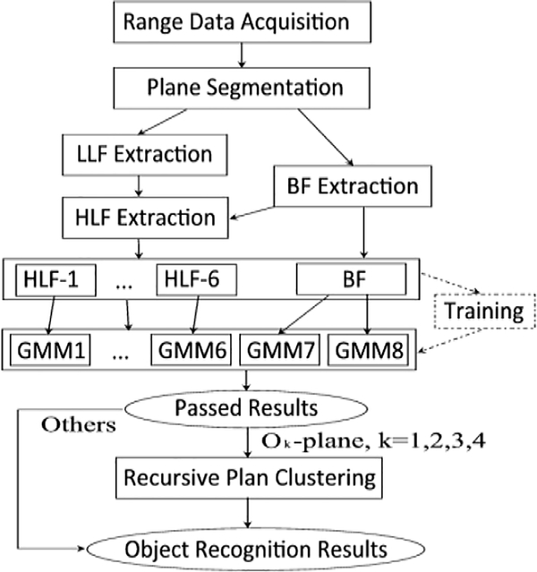
The state-of-the-art graph-based object recognition method [19] is of NP complexity. For computational efficiency, we propose a Gaussian-Mixture-Model (GMM) based object recognition method as depicted in Fig. 5. It consists of five main procedures: range data acquisition, plane extraction, feature extraction, GMM Plane Classifier design and training, and plane clustering. Each of them is described in this section.
Fig. 5.
Diagram of the proposed object recognition method
A. Range Data Acquisition and Plane Segmentation
Using the estimated poses, the 3D range data of the camera are registered to form a large 3D point cloud map. The point cloud data is then segmented into N planar patches, P1, P2, …, PN, by the NCC-RANSAC method [20].
B. Features and Feature Vectors
Each of the N patches is then assigned a feature vector that describes its intrinsic attributes and geometric context, i.e., Inter-Plane Relationships (IPRs) representing the geometric arrangement with reference to another planar patch. In this paper, we define three classes of features—Basic Feature (BF), Low Level Feature (LLF), and High Level Feature (HLF).
Basic Features:
BFs are local features that describe a patch’s intrinsic attributes. They serve as the identity of the patch. Similar to [19], three BFs—Orientation, Area and Height (OAH)—are defined for a planar patch. They are computed as the angle between the patch’s normal and Z-axis, size of the patch, and the maximum Z coordinate of the points in the patch, respectively. The computational details are omitted for simplicity.
Low Level Features:
To classify a patch into a constituent element of a model object, the patch’s IPR must be considered in addition to its BFs. The following 9 IPRs are defined for patch Pi with reference to patch Pj: (1) plane-distance is a value representing the minimum distance between the points of Pi and the points of Pj; (2) plane-angle represents the angle between Pi and Pj; (3) parallel-distance, denoted , represents the distance between two parallel planes, Pi and Pj, and is computed as the mean of the distance from the centroid of Pi to patch Pj and the distance from the centroid of Pj to patch Pi; (4) projection-overlap-rate is a value representing to what extent Pi overlaps Pj and it is calculated as the area ratio of the projected Pi (onto Pj) to Pj; (5) projection-distance is the minimum distance from the points of Pi to plane Pj; (6) is-parallel describes if Pi is parallel to Pj (1: parallel, 0: not parallel); (7) is-perpendicular describes if Pi is perpendicular to Pj (1: perpendicular, 0: not perpendicular); (8) is-coplanar describes if Pi is co-planar with Pj (1: coplanar, 0: not coplanar); (9) is-adjacent describe if Pi is adjacent to Pj. (1: adjacent, 0: not adjacent). Due to the SR4000’s noise, threshold values are used in computing the above LLFs. The details are omitted. Since there are N patches, an N×N matrix is formed to record each of the 9 IPRs among the N patches. Each matrix is called an LLF. In an LLF matrix, an element at (i, j) describes the IPR of Pi with reference to Pj. For example, is-parallel(i, j)=1 indicates that Pi is parallel to Pj.
High Level Features and Feature Vectors:
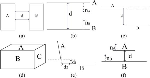
In this work, each planar patch is classified as a plane belonging to one of the eight objects (models). To this end, we define 6 mutually exclusive High Level Features (HLFs) as shown in Fig. 6. Each HLF represents a set of particular IPRs that exists in an object model. The HLF extraction is a process to identify the HLF for each of the N planar patches and assign each patch an HLF vector. The BFs extracted earlier are used in constructing the HFL vector. We first construct a BF vector [O, A, H] for a planar patch. Each BF is then extended based on the patch’s HLF. For a patch with HLF-1, HLF-2, HLF-3 or HLF-6, we add parameter d into its BF vector to form a HLF vector [O, A, H, d]. For a patch with HLF-5, we add parameter d1 and d2 to form a HLF vector [O, A, H, d1, d2]. For a patch with HLF-4, we simply use the BF vector as the HLF vector. A plane is treated as an object if it is a wall/ground. Such a plane does not have an IPR. We therefore simply use its BF vector as the HLF vector. A plane with an HLF as depicted in Fig. 6 is called a complex plane, while a wall/ground plane an elementary plane.
Fig. 6.
Definition of HLFs: (a) HLF-1: co-planar with distance d; (b) HLF-2: parallel and face-to-face with distance d; (c) HLF-3: step-shape with distance d; (d) HLF-4: parallelepiped-shape; (e) HLF-5: side-above with distance d1 and d2: d1 is the A’s projection-distance while d2 is the minimum distance between A’s projection-points on B and B’s points; (f) HLF-6: above-with-distance d. A, B and C represent any three patches out of the N planar patches.
For each of the N planar patches, the LLF matrix is analyzed to detect the HLFs and the corresponding feature vector is assigned to the patch for each detected HLF. The assigned HLF vectors are then sent to the GMM Plane Classifier (GMM-PC) (Fig. 5) for plane classification. The HLF vector assignment process also generates 6 matrices, Q1 ,…, Q6, each of which records the N planar patches’ IPRs for HLF-1, …, HLF-6, respectively.
C. GMM Plane Classifier
The GMM-PC consists of 8 GMMs, each of which has been trained using data captured from a particular type of objects and is thus able to identify a plane related to that type of object when the relevant HLF vector is present. For simplicity, we call a GMM for detecting object type Ok for k =1, ⋯, 8, an Ok-GMM. Here, O1, O2,…, O8 represent doorway, hallway, stairway, parallelepiped, monitor, table, ground and wall, respectively. We call a plane belonging to object Ok an Ok-plane and a scene with object Ok an Ok-scene. In the GMM-PC, the Oi-GMM receives all HLF-i vectors and determine if each vector’s associated patch is an Oi-plane (here, i =1, ⋯, 6). The ground-GMM and the wall-GMM receive the remaining BFs and classify each of the associated planar patches into a ground-plane or a wall-plane.
A GMM is a probability density function represented as a weighted sum of M Gaussian component densities given by:
| (3) |
where x is a D-dimensional (in our case, D=3, 4 or 5) vector with continuous values, ωi, i = 1,…,M, are the mixture weights, and g(x|μi, Σi), i = 1,…,M, are the component Gaussian densities with mean vector μi and covariance matrix Σi. The mixture weights satisfy . The complete GMM is parameterized by μi, Σi and ωi for i = 1,…,M. We denote these parameters collectively by λ from now on for conciseness. In this paper, the configuration (M and λ) of an Ok-GMM is estimated by training the GMM using a set of HLF vectors obtained from a number of Ok-scenes. The maximum likelihood estimate of λ is iteratively obtained by the Expectation Maximization (EM) method. The value of M is determined by repeating the training process with an increasing i and observing the trained GMM’s output p(x|λ). If the mean of the output difference between an I-component GMM and an (I+1)-component GMM is below a threshold, we let M=I because more Gaussian component densities will not change the GMM’s probability density.
We acquired 500 datasets from different Ok-scenes. After plane segmentation and feature extraction, we obtained a set of HLF vectors from each dataset. We then trained the Ok-GMM using these HLF vectors. The training process determined the Ok-GMM’s configuration (M and λ). The smallest probability density of the trained Ok-GMM for the training data is recorded as the threshold for plane classification in a later stage.
After the training, each GMM of GMM-PC is able to classify a patch into one of the eight plane types using the patch’s HLF vector. To be specific, a planar patch’s HLF (or BF if an HLF is unavailable) is presented to the relevant GMM. The GMM’s output, pk(X|λ) for k = 1,⋯,8, is compared with If , the planar patch is classified as an Ok-plane. In case that a patch is classified as both an elementary plane and a complex plane, the complex plane classification overrides the elementary one. All extracted HLF vectors are presented to the GMM-PC and the corresponding planar patches are classified into the eight types of planes. The GMM-PC results in 8 arrays, Gk for k = 1,⋯,8, each of which stores the indexes of the planar patches that have been classified as Ok-planes.
D. Recursive Plane Clustering
In this stage, the classified planes, Ok-planes for k = 1,⋯,4, are recursively clustered into a number of objects, Ok for k = 1,⋯,4. This means that the doorway-/hallway-/stairway/parallelepiped-planes are grouped into doorway(s) /hallway(s)/stairway(s)/parallelepiped(s) by a Recursive Plane Clustering (RPC) process. A monitor-/table-/ground-/wall-plane is treated as a standalone object and thus no further process is needed. Four recursive procedures, RPC-1, …, and RPC-4, process G1, …, G4, respectively and cluster the neighboring object planes into the four types of objects by analyzing Q1 ,…, Q4.
VI. Experimental Results
We collected data from various scenes inside a number of buildings on campus to train and/or test the methods. Five students who are not the developers of the methods participated in data collection.
A. Pose Estimation
We carried out 9 experiments (Group I) in feature-rich environments and 5 (Group II) in feature-sparse environments. In each experiment, the CRC user walked with the cane in a looped trajectory (path-length: 20–40 meters). The CRC’s Final Position Error (FPE) (in percentage of path-length) is used as the overall accuracy of pose estimation. The PGO method’s FPE is compared with that of the baseline (dead reckoning) method and the percentage error reduction indicates the performance of PGO. The results are tabulated in Table I. The PGO method reduces the FPEs in all cases in feature-sparse environments. For feature-rich environments, the PGO slightly increases the FPEs in 4 cases but substantially decreases the FPEs in the other 5 case. Overall, the method improves the pose estimation results in feature-rich environments. It can be seen that the PGO achieves a much larger and more consistent pose estimation improvement in a feature-sparse environment. This property will benefit indoor navigation where feature-spare scenes occur from time to time.
Table I.
Performance of the PGO method in various environments
| Group I | FPE [%] | ER [%] | Group II | FPE [%] | ER [%] | ||
|---|---|---|---|---|---|---|---|
| DR | PGO | DR | PGO | ||||
| 1 | 4.45 | 2.65 | 1.80 | 1 | 3.01 | 1.15 | 1.86 |
| 2 | 2.97 | 2.37 | 0.60 | 2 | 3.58 | 2.50 | 1.08 |
| 3 | 2.71 | 3.07 | −0.36 | 3 | 2.42 | 2.23 | 0.19 |
| 4 | 2.66 | 2.50 | 0.16 | 4 | 4.17 | 2.75 | 1.43 |
| 5 | 1.2 | 1.33 | −0.13 | 5 | 2.21 | 1.64 | 0.57 |
| 6 | 2.03 | 2.28 | −0.25 | ||||
| 7 | 2.05 | 0.46 | 1.59 | ||||
| 8 | 5.7 | 4.71 | 0.99 | ||||
| 9 | 3.3 | 3.79 | −0.49 | ||||
| Mean | 0.43 | Mean | 1.02 | ||||
| Standard Deviation | 0.86 | Standard Deviation | 0.67 | ||||
DR: Dead Reckoning, ER: Error Reduction, FPE: Final Position Error
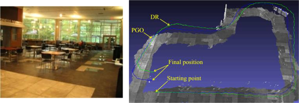
Fig. 7 depicts the result of experiment 1 in Group I. It can be observed that the FPE of the PGO algorithm is much smaller than that of the dead reckoning method.
Fig. 7.
Pose estimation in a feature-rich environment (experiment 1 in Group I). Left: snapshot of scene; Right: CRC’s trajectories estimated by the dead reckoning and PGO methods plotted over the 3D point cloud map.
B. Object Recognition
We collected 60 data sets from each type of scenes, half (Type I) from the same scenes that were used for GMM training and the other half (Type II) from similar scenes with the same type of objects. We ran the object recognition method on the 480 (8×60) datasets and evaluated its performance in term of the success rate of object recognition. The results are tabulated in Table II. For each object type, the success rates on Type I data are slightly higher than that on Type II data because the GMM was trained using the similar type of data. The fact that the success rate on Type II data is over 86.7% (except for monitor scenes) indicates that the trained GMMs generalize well in object recognition.
Table II.
Success rates in object recognition
| Object Type | Type I Data | Type II Data | Average |
|---|---|---|---|
| Stairway | 0.967 | 0.900 | 0.933 |
| parallelepiped | 1.000 | 0.933 | 0.967 |
| Hallway | 1.000 | 1.000 | 1.000 |
| Doorway | 0.933 | 0.867 | 0.900 |
| Table | 1.000 | 0.967 | 0.983 |
| Monitor | 0.900 | 0.800 | 0.850 |
| Wall | 1.000 | 1.000 | 1.000 |
| Ground | 1.000 | 1.000 | 1.000 |
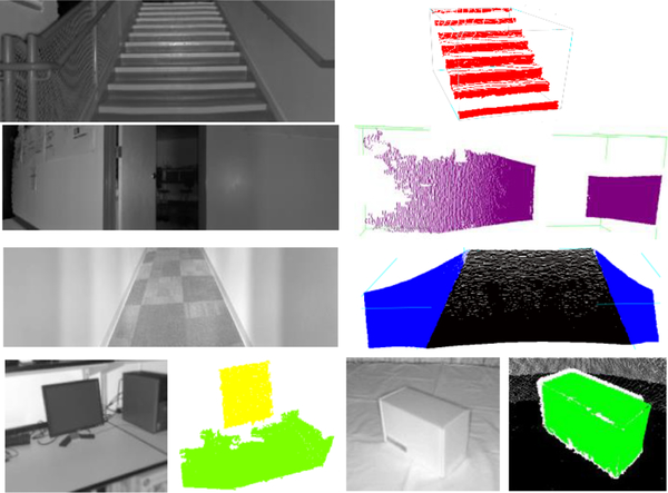
Fig. 8 depicts the object recognition results on stairway, doorway, hallway, parallelepiped (box), monitor, desk and grounds. In all cases, the proposed method detects and labels the objects correctly. We have also run the object recognition method on two range data sets, each of which consists of multiple views of the scene, collected in our lab and nearby a stairway, respectively. In either case, the estimated CRC poses were used for range data registration. The method successfully detected all target objects, including desks, monitors, walls, stairway and grounds. The results demonstrate that the method can accommodate the PGO pose estimation errors.
Fig. 8.
Experimental results with a doorway, hallway and box. Left: intensity image; Right: 3D view of the detected objects (stair in red, doorway in purple, hallway in blue, desk in light green, parallelepiped in green, grounds in black).
VII. Conclusions and Discussions
We have presented the concept of the CRC for indoor navigation of a visually impaired individual. As a co-robot, the CRC detects human-intent and uses the intent to automatically choose the device’s use mode. In the active mode, the CRC may steer into the desired direction of travel and thus provide accurate guidance to a blind traveler. Three technology components—human intent detection, pose estimation and 3D object recognition—have been developed to enable wayfinding and obstacle avoidance by using a single 3D imaging sensor. The design of the CRC takes into account safety: if all robotic functions fail, the CRC degrades itself into a white cane that can still be used as a conventional mobility tool for navigation.
The CRC is in its development stage. We are working with the orientation and mobility specialists and blind trainees of the World Service for the Blind (Little Rock, AR) in designing and refining the CRC functions. By the time of writing this paper, we have just built and tested two standalone systems, one for object detection and the other for wayfinding. A speech interface was used for human-device interaction. The object detector is working properly at present and it announces the detection result when pointed towards a known object. In our tests, we used single frame range data for the sake of realtime object detection. The wayfinding system locates the user on a floor and guides the user to the destination using the pose estimation method and the floorplan. In the current tests, the CRC’s starting point and the initial heading is assumed to be known. It was found that an early orientation error created by the pose estimation method may accrue a big position error over time and make the system out of work. A temporary solution was to extract the wall from the range data and match the wall to the floorplan to reset the error periodically. Using this scheme, the wayfinding system successfully guided a user (blind-folded) to the destinations by the speech interface. It was also found that the system worked well when the swing speed is moderate (<30°/s). In the future, we will use the result of the 3D object detection method to reset the accumulative pose error. In addition, a method to determine the initial position and heading will be developed for wayfinding. Finally, the method in [21] may be used to provide the system with tactile landmark(s) to recover the system from a total failure of pose estimation. It is noted that we do not consider loop closure issue in this paper. The reasons are twofold. First, most wayfinding tasks do not have a closed path. Second, existing loop closure detection methods are computationally costly and thus impractical for the CRC as they compare the current image frame with a large number of previous key image frames.
Acknowledgments
This work was supported in part by the NIH under award R01EB018117, NASA under award NNX13AD32A, and the NSF under award IIS-1017672. The content is solely the responsibility of the authors and does not necessarily represent the official views of the funding agencies.
Biography
 Cang Ye (S’97–M’00–SM’05) received the B. E. and M. E. degrees from the University of Science and Technology of China, Hefei, Anhui, in 1988 and 1991, respectively, and the Ph.D. degree from the University of Hong Kong, Hong Kong in 1999. He is currently a Professor with the Department of Systems Engineering, University of Arkansas at Little Rock, Little Rock, AR. His research interests are in mobile robotics, intelligent system, and computer vision.
 Soonhac Hong (M’15) received the B.S. and M.S. degrees in Mechanical Engineering from Hanyang University, Seoul, South Korea, in 1994 and 1996, the M.S. degree in Computer Science from Columbia University in 2010, and the Ph.D. degree from University of Arkansas at Little Rock in 2014. He is currently a Senior Researcher of Systems, Algorithms & Services at Sharp Labs of America, Camas, WA, USA. His research interests include simultaneous localization and mapping, motion planning, computer vision, and machine learning.
 Xiangfei Qian (SM’14) received BS degrees in Computer Science from Nanjing University, Nanjing, China, in 2011. Since 2011 August, he is currently a Ph.D. student with the Department of Systems Engineering, University of Arkansas at Little Rock. His research interests include 2D/3D computer vision, pattern recognition, and image processing.
 Wei Wu received the B.S. degree in Measurement Control and Instruments from Henan University, Kaifeng, China, in 2002. He is currently pursuing the Ph.D. degree at the Department of Systems Engineering, University of Arkansas at Little Rock, Little Rock. His current research interests include 2D/3D computer vision, SLAM, and image processing.
Contributor Information
Cang Ye, Dept. of Systems Engineering, University of Arkansas at Little Rock, Little Rock, Arkansas 72204 United States.
Soonhac Hong, Dept. of Systems Engineering, University of Arkansas at Little Rock, Little Rock, Arkansas United States.
Xiangfei Qian, Dept. of Systems Engineering, University of Arkansas at Little Rock, Little Rock, Arkansas United States.
Wei Wu, Dept. of Systems Engineering, University of Arkansas at Little Rock, Little Rock, Arkansas United States.
References
- [1].Galindo C, et al. , “Control Architecture for Human-Robot Integration: Application to a Robotic Wheelchair,” IEEE Trans. Syst., Man, Cybern. B, Cybern, vol. 36, no. 5, pp. 1053–1067, 2006. [DOI] [PubMed] [Google Scholar]
- [2].Ulrich I and Borenstein J, “The GuideCane−Applying Mobile Robot Technologies to Assist the Visually Impaired,” IEEE Trans. Syst., Man, Cybern. A, Syst. and Humans, vol. 31, no. 2, pp. 131–136, 2001. [Google Scholar]
- [3].Kulyukin V, et al. , “Robot-Assisted Wayfinding for the Visually Impaired in Structured Indoor Environments,” Autonomous Robots, vol. 21, no. 1, pp. 29–41, 2006. [Google Scholar]
- [4].Bissit D and Heyes A, “An Application of Biofeedback in the Rehabilitation of the Blind,” Applied Ergonomics, vol. 11, no. 1, pp. 31–33, 1980. [DOI] [PubMed] [Google Scholar]
- [5].Benjamin JM, Ali NA, and Schepis AF, “A Laser Cane for the Blind,” in Proc. San Diego Medical Symposium, 1973, pp. 53–57. [Google Scholar]
- [6].Yuan D and Manduchi R, “A Tool for Range Sensing and Environment Discovery for the Blind,” in Proc. IEEE Computer Vision and Pattern Recognition Workshops, 2004, pp. 39. [Google Scholar]
- [7].Balachandran W, Cecelja F, and Ptasinski P, “A GPS Based Navigation Aid for the Blind,” in Proc. 17th Int. Conf. on Applied Electromagnetics and Communications, 2003, pp. 34–36, 2003. [Google Scholar]
- [8].Wilson J, et al. , “SWAN: System for wearable audio navigation,” in Proc. 11th IEEE Int. Symp. Wearable Comput., 2007, pp. 91–98. [Google Scholar]
- [9].Hesch JA and Roumeliotis SI, “Design and Analysis of a Portable Indoor Localization Aid for the Visually Impaired,” The International Journal of Robotics Research, vol. 29, no. 11, pp. 1400–1415, 2010. [Google Scholar]
- [10].Ye C, Hong S and Qian X, “A Co-Robotic Cane for Blind Navigation,” in Proc. IEEE Int. Conf. on Syst., Man, and Cybernetics, 2014, pp. 1082–1087. [Google Scholar]
- [11].Ye C and Bruch M, “A Visual Odometry Method based on the SwissRanger SR4000,” in Proc. SPIE 7692, Unmanned Systems Technology XII, 2010. [Google Scholar]
- [12].Lowe DG, “Distinctive image features from scale-invariant keypoints,” Int. J. Computer Vision, vol. 2, no. 60, pp. 91–110, 2004. [Google Scholar]
- [13].Arun KS, et al. , “Least square fitting of two 3-D point sets,” IEEE Trans. Pattern Anal. Mach. Intell, vol. 9, no. 5, pp. 698–700, 1987. [DOI] [PubMed] [Google Scholar]
- [14].Hong S, Ye C, Bruch M and Halterman R, “Performance Evaluation of a Pose Estimation Method Based on the SwissRanger SR4000,” in Proc. IEEE ICMA, Chengdu, China, 2012, pp. 499–504. [Google Scholar]
- [15].Hong S and Ye C, “A Fast Egomotion Estimation Method based on Visual Feature Tracking and Iterative Closest Point,” in Proc. IEEE Int. Conf. on Networking, Sensing and Control, 2014, pp. 114–119. [Google Scholar]
- [16].Hong S and Ye C, “A Pose Graph based Visual SLAM Algorithm for Robot Pose Estimation,” in Proc. World Automation Congress, 2014, pp. 917–922. [Google Scholar]
- [17].Grisetti G, et al. , “A Tutorial on Graph-Based SLAM,” IEEE Intelligent Transportation Systems Magazine, vol. 2, no. 4, pp. 31–34, 2010. [Google Scholar]
- [18].GTSAM 2.3.0 (https://collab.cc.gatech.edu/borg/gtsam/).
- [19].Xiong X and Huber D, “Using context to create semantic 3D models of indoor environments,” In Proc. British Machine Vision Conf, 2010, pp. 45.1–45.11 [Google Scholar]
- [20].Qian X and Ye C, “NCC-RANSAC: A Fast Plane Extraction Method for 3D Range Data Segmentation,” IEEE Trans. Cybern, vol. 44, no. 2, pp. 2771–2783, 2014. [DOI] [PMC free article] [PubMed] [Google Scholar]
- [21].Apostolopoulos I, et al. , “Integrated online localization and navigation for people with visual impairments using smart phones,” ACM Trans. Interact. Intell. Syst, vol. 3, no. 4, pp. 1–28, 2014. [Google Scholar]


