Abstract
Purpose:
To investigate the feasibility of using an electromagnetic (EM) tracker to estimate rigid body head motion parameters, and using these measurements to retrospectively reduce motion artifacts.
Methods:
A clinically used MPRAGE sequence was modified to measure motion using the EM tracking system once per repetition time. A retrospective k-space based motion correction algorithm that corrects for phase ramps (translation in image domain) and rotation of 3D k-space (rotation in image domain) was developed, using the parameters recorded using an EM tracker. The accuracy of the EM tracker for the purpose of motion measurement and correction was tested in phantoms, volunteers and pediatric patients.
Results:
Position localization was accurate to the order of 200 microns compared to registration localization in a phantom study. The quality of reconstructed images was assessed by computing the root mean square error, the structural similarity metric and average edge strength. Image quality improved consistently when motion correction was applied in both volunteer scans with deliberate head motion and in pediatric patient scans. In patients, the average edge strength improved significantly with retrospective motion correction, compared to images with no correction applied.
Conclusions:
Electromagnetic tracking was effective in measuring head motion in the MRI scanner with high accuracy, and enabled retrospective reconstruction to improve image quality by reducing motion artifacts.
Keywords: MRI motion correction, external trackers
INTRODUCTION
Subject motion during MR image acquisition has been shown to be a frequent cause of image artifacts and dramatically increases the time and cost involved in acquiring diagnostically useful images with MRI [1]. This is especially critical in pediatric populations where, even in a cooperative cohort, 14% of the scans were non-diagnostic and 35% of cases had major motion artifacts [2]. It is common practice for a high percentage of children (especially aged 4–7 years) to be scanned under general anesthesia or full sedation. Unfortunately, sedation and anesthesia in children can have substantial risks and also significantly increases the cost of each scan [3][4]. A technology that successfully reduces the effects of motion on MRI quality could potentially eliminate the need for sedation, resulting in both reduced costs and reduced risks to patient health.
Some promising prospective and retrospective correction techniques have been suggested in earlier work but their clinical adaptation has been limited. Self-navigated techniques that are intrinsically robust to motion such as PROPELLER [5], radials [6,7] and spirals [8] have been made available in commercial scanners. These techniques acquire the k-space center in each shot and this is used to estimate and correct for motion. The primary limitations of these methods are the limited types of motion that can be captured and corrected for, the potential for increased scan time caused by oversampling, and the lack of flexibility with regard to tissue contrast.
It is also possible to estimate and correct for motion using navigators that acquire additional k-space data or parts of an image at each k-space line or partition acquisition. Many different navigators have been suggested [9–11], ranging from FID navigators [12,13], which only acquire the center of the k-space in minimal time, to volume navigators [14] that acquire a whole image using single-shot 3D EPI acquisition blocks. Each of these methods offers a trade-off between increased scan time versus accuracy of motion measurements.
Alternatively, external tracking systems, such as RF probes [15,16] or optical cameras [17–20], can be used to measure motion in real-time. The main advantages of measuring motion using an external device are that no substantial sequence changes are necessary and motion measurement timing is independent of the underlying sequence. Although there have been a number of studies on external trackers in research MRI, clinical adoption has been limited. The assumption that the tracking device or marker is attached rigidly to the subject can produce inaccurate motion measurement results due to skin motion. For optical trackers, the requirement for a line of sight between the camera and marker may be difficult to meet in a clinical MRI workflow, especially for pediatric MRI. Furthermore, many systems require frequent calibration to establish the mapping between the scanner and the tracker coordinate systems, which may be an additional challenge for the clinical imaging workflow.
In this work, we investigate the feasibility of improving neuroimaging using an electromagnetic (EM) tracker to measure rigid body motion, and to retrospectively correct for motion artifacts. The system is based on an initial design described by Roth et al [21]. We worked on the system with Robin Medical to improve its usability in clinical setting by reducing the size of the sensors, optimizing the materials to eliminate the B0 artifacts, designing a headband that is suitable for pediatric populations, and implementing clinical sequences with the activation gradients so that real-time tracking is possible. The EM trackers consist of six RF coils and the system uses a mapping of the gradient system to estimate the position and orientation of each sensor by analyzing the induced currents on these coils at different position and orientations. Since the EM tracking system does not require a line of sight, it is possible to avoid problems of using a single sensor by utilizing multiple sensors at the same time, as explored in this study. In addition, the EM tracking system requires calibration only at the installation of the system or following a major system upgrade.
To this end we modified an MPRAGE sequence to measure motion once per TR using EM trackers and used the motion traces from multiple sensors to retrospectively correct for subject motion. We first tested our framework in phantom studies to establish the accuracy and precision of the system to measure and correct for motion. We then tested the system in healthy volunteer studies. We recruited pediatric subjects undergoing routine clinical imaging, and carried out additional motion tracked imaging with the EM tracker in the clinical MRI environment. Our results show that retrospective correction using EM tracker motion data can be used to reduce the effects of motion in both research and clinical imaging scenarios.
THEORY
Motion measurements using EM trackers:
The basic unit of the EndoScout system (Robin Medical Inc, Baltimore MD) is a 1 cm cubic sensor, with a coil on each face that can detect changing magnetic fields induced by the switching gradients used during imaging. The system does not introduce any significant heating or B0 field changes during normal operation of the magnet. During system installation, the gradient fields are mapped by measuring the signal induced in a sensor coil at different locations and orientations throughout the operating volume of the tracking system, which covers the whole head coil. The mapping procedure is performed only at the time of installation or when a major hardware change occurs on the scanner, i.e. gradient coil changes. During the mapping procedure, each gradient is activated separately with a known reference slew rate. The measured signals in the coils are processed to construct maps of the gradient field distributions.
During routine scanning with motion tracking, the instantaneous magnetic field at each location is the sum of fields generated by the three gradient fields (Gx(t), Gy(t), Gz(t)) having instantaneous slew rates (Rx(t),Ry(t),Rz(t)). By using the measured voltages induced in each coil and fitting these voltages to the mapping parameters, the system can determine the position and orientation of the sensor inside the scanner bore. This requires that all gradient axes be activated at some time during the measurement window, which may be as short as several milliseconds. This condition is satisfied by some standard sequences, and additional gradients can be added to most other sequences to provide robust activation of all axes throughout the scan without affecting image quality.
In this hardware setup, each sensor is connected to a multiplexer box inside the scan room via a wire. The multiplexer then sends the sorted signals to a computer inside the console room via a synchronizer. The synchronizer has an update rate of 200kHz. Every 10 ms the system searches for an activation gradient in a 10 ms window to synchronize the sequence and the system computer. The latency is on the order of 100 microseconds. The computer calculates and saves the position and orientation information in real-time and displays the motion traces on a graphical user interface, enabling the operator to visualize how much the subject is moving. The system is connected to the optical trigger of the MR scanner to know when the sequence starts. The computer also calculates a cost function indicating how well the measured voltages on each sensor can be estimated using the mapping parameters. The cost function becomes high if there is a problem in the signal measurement or if the sensor moves out of the mapped area. The mapped area includes the whole volume of the head coil so this was not a problem with the imaging experiments described in this paper. The accuracy of the system is lower if the sensors are very close to the isocenter of the magnet in all three directions, but due to the design of the headband with four sensors distributed in x and y directions, this behavior was not observed.
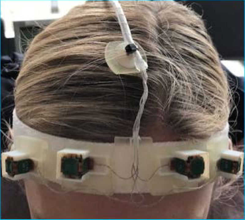
Since there is no requirement for line of sight to the sensors, it is possible to use multiple sensors at the same time. The system currently uses four sensors attached to the forehead of the subject using a headband designed to minimize non-rigid motion and skin motion. The use of four sensors reduce the possibility of a system malfunction in case of the sensor malfunctions and also reduces the effect of skin motion. Figure 1 shows the headband and sensors on a volunteer. For newborns and younger children, a smaller sized headband was used.
Figure 1:
Four EM sensors mounted on a headband designed to minimize non-rigid motion, shown on a volunteer.
Sensor data combination:
The system reports the orientation of each sensor by two orthogonal unit vectors and the position of each sensor (x,y,z) with respect to the isocenter of the magnet at each time point. First, we use the cost function reported by the system to eliminate a sensor in case the sensor has a malfunction or it is out of the mapped region. Using the first three points in time, we compute reference position and orientation vectors p0,i and v0,i for each sensor i. Then we estimate the rotation matrix R using singular value decomposition of the covariance matrix of the reference vectors v0,i and new measurements vt,i, (i.e. vt*v0’). We calculate the mean reference position p0 from p0,i and for each new position pt from pt,i. Then the optimal translation is calculated as t=pt-R*p0. For the work described in this manuscript there were no additional filters applied to the data as the time difference between each measurement was on the order of seconds, i.e. one measurement per inversion pulse in MPRAGE sequence. For other sequences, such as a GRE sequence where motion can be measured on the in the order of milliseconds, filtering the data using a median filter or a Kalman filter [9,22] should be considered to estimate a consistent motion trajectory.
METHODS
Imaging Sequence:
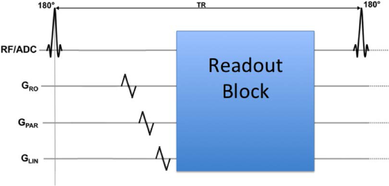
We modified a T1-weighted MPRAGE sequence that is used clinically at our institution with additional gradient activations to enable tracking once per TR. The additional gradients are placed just before each inversion recovery pulse as shown in Figure 2. On each gradient axis (Gx,Gy,Gz) one blip up/down gradient with a duration of 1 ms was added.
Figure 2:
Three blip up/down gradients can be placed at any point in the sequence where there is a 1 ms empty period, to enable the determination of the position of each sensor at that instant.
The echo time (TE) of the scan was 2.17 ms with a repetition time (TR) of 1.56 s. The field of view was 256×256×176 mm3 with a matrix size of 256×256×176, resulting in an isotropic 1 mm resolution. The inversion time (TI) was set at 800 ms with a flip angle of 9° and a bandwidth of 200 Hz/pixel. GRAPPA was used in the phase encoding direction with 2X acceleration resulting in a total scan time of 4 minutes and 10 seconds.
Image Reconstruction:
Raw k-space data was extracted from the scanner and each k-space line (from each coil) was corrected for phase ramps (translation in image domain) and regridded in 3D k-space using the NUFFT toolbox (rotation in image domain) using the estimated rigid body motion parameters as suggested by Gallichan et al [23]. After the motion-corrected images were reconstructed for each coil, the adaptive combine method [24] was used to create the final image.
Motion experiments:
All imaging was performed at 3T (Trio, Siemens Healthcare, Erlangen, Germany) using a product 32-channel head coil. All subjects gave written informed consent prior to imaging and all scans were performed in accordance with the local Institutional Review Board approved protocol.
1). Phantom Experiments:
A pineapple was imaged with the motion tracked MPRAGE sequence. In order to calculate the accuracy of the EM tracker, eight different MPRAGE volumes were acquired with a 45-second pause in between. The pineapple was moved manually during those 45 seconds to a different position such that the maximum rotation was below 8° and maximum translation was below 8 mm. Each acquired volume was then registered to the first volume using ITK rigid-body registration with a mutual information metric to generate reference parameters for motion. These rigid body registration parameters were then compared to the EM tracker motion measurements. Each image was motion corrected using the EM tracker motion measurements and average images for each method, i.e. no correction, registration and EM tracker correction, were calculated by taking the mean of the images from eight different positions.
2). Volunteer Experiments:
Six volunteers were scanned with the motion tracked MPRAGE sequence. A total of four volumes were acquired on each volunteer. Subjects were instructed to perform the following directed motion experiments to simulate a variety of motion conditions:
Remain as still as possible for the duration of the scan (small involuntary motion only)
Perform a series of four abrupt movements, where subjects were instructed to a move to a random position and stay there until the next voice command (abrupt movement)
Perform a series of abrupt head nodding movements between “up” and “down” positions, instructed to switch every 30 seconds (abrupt nodding)
Perform continuous head nodding in such a way that subjects switch from nodding up-down to down-up every 30 seconds (continuous nodding)
All instructions were given verbally through the scanner intercom system. Before each experiment, the subject was trained to do each of the three different motion experiments (i.e. abrupt movement, abrupt nodding and continuous nodding) with motions below 5° rotation and 5 mm translation. This training was accomplished by giving verbal cues in a scan where the operator observed the motion traces in real time. These values were chosen using our initial work on pediatric populations [2] and on our simulations determining the range of motion where retrospective correction results in good image quality.
The raw data from all four scans was saved and reconstructed using the retrospective motion construction algorithm described above. The “no motion” scan without any correction for each subject was selected as the reference scan and each motion scan with and without retrospective motion correction was compared to that reference scan. The voxel-wise normalized root-mean-square error (NRMSE) and the structural similarity (SSIM) index [25] were calculated within the segmented brain region (using FSL tool BET [26]) relative to this motion-free reference image. Furthermore, a reference-free metric, average edge strength (AES) was calculated for each scan. As suggested by Aksoy et al. [27], AES values were normalized by the corresponding slice in the “no motion” dataset. Paired Wilcoxon signed-rank tests were performed to determine if motion correction using EM tracker improved these quantitative image metrics compared to no correction.
3). Patient Scans:
The correction algorithm was also tested on eight pediatric patients scanned at our institution. Parents of patients gave written informed consent and children older than 7 years old gave their assent. The average age of the patients was 7.9 ± 2.4 years old, where the youngest patient was 4 years old and oldest was 12 years old. The sensors were attached using a headband during a motion tracked MPRAGE sequence. Since there is no reference image for these studies, image quality was evaluated using AES and visual inspection. AES was normalized using the uncorrected scan for each patient (as a reference “no motion” image is not available) effectively generating an AES improvement metric due to motion correction.
RESULTS
Figure 3 shows a comparison between the translation and rotation parameters measured using the EM tracker for the phantom experiment with inter-scan motion and registration between each volume. As reported in Table 1, EM tracker has an accuracy of around 200 microns compared to the registration results; 0.121 ± 0.136 mm for translation and 0.069 ± 0.076° for rotation for motions below 8 mm and 8°.
Figure 3.
Comparison of motion measurements using EM tracker and registration between each position, illustrating the high accuracy of the system, in a phantom study. Solid lines show the measurements provided by the EM tracker for each TR, whereas dotted lines show the registration results. As shown in the right panel, EM tracker results are in excellent agreement with the registration results.
Table 1.
Summary of the accuracy (absolute error) and precision (standard deviation) of EM tracking motion estimates from a phantom experiment with inter-scan motion. Motion measurements are recorded from the EM tracker at each TR (135 points) for all eight positions. For each motion parameter, we calculate the absolute difference between this signal and the ground truth motion corresponding to that TR, calculated by registration between eight positions. We report the mean and variance of this difference in the table. Both translation and rotation demonstrate high accuracy and precision. The overall root mean square accuracy was on the order of 200 microns.
| Translation (mm) | Rotation (°) | |||||||
|---|---|---|---|---|---|---|---|---|
| x | y | z | Mean | ψx | θy | ϕz | Mean | |
| Accuracy | 0.111 | 0.126 | 0.128 | 0.121 | 0.030 | 0.049 | 0.129 | 0.069 |
| Precision | 0.152 | 0.076 | 0.183 | 0.136 | 0.033 | 0.092 | 0.103 | 0.076 |
| Max. Motion | 7.45 | 2.09 | 7.83 | 1.88 | 6.84 | 3.76 | ||
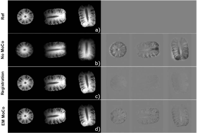
Figure 4 shows the results of retrospective correction between eight volumes acquired using an EM tracked MPRAGE sequence. The top row shows the reference image (position 1). The second row shows the average of eight volumes, resulting in blurry images since the pineapple is in a different position at each acquisition. The third row shows results from the registration approach, where each volume was registered to the reference volume using a 3D rigid body registration and the mean image was calculated for all eight registered images. The last row shows the images corrected using the translation and rotation parameters reported by the EM tracker, again averaged for all eight corrected images. NRMSE of the mean image (relative to the reference image) was 11.97% for no motion correction and reduced to 3.65% with registration and 5.38% with EM tracker measurements. Similarly, SSIM improved from 0.452 (no correction) to 0.961 for registration and 0.963 for EM tracker correction.
Figure 4:
Axial, sagittal and coronal slices through average of eight pineapple scans without any correction, after registration and after correction of k-space lines with EM tracker motion estimates; difference relative to reference position. Both registration and correction using EM tracker measurements reduces the errors compared to no motion correction.
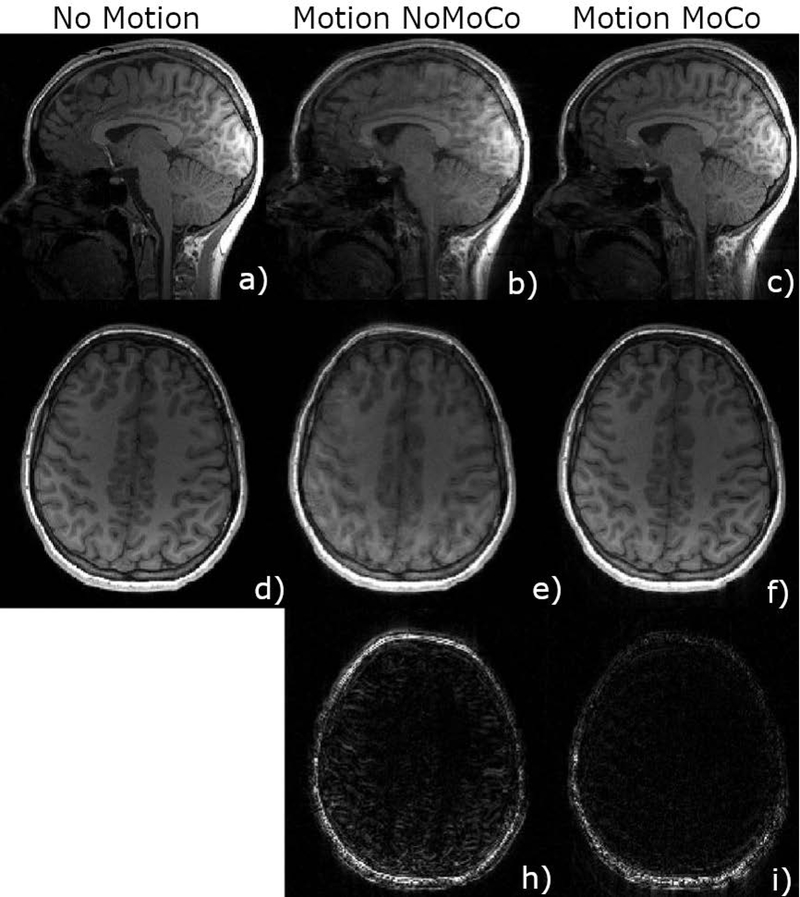
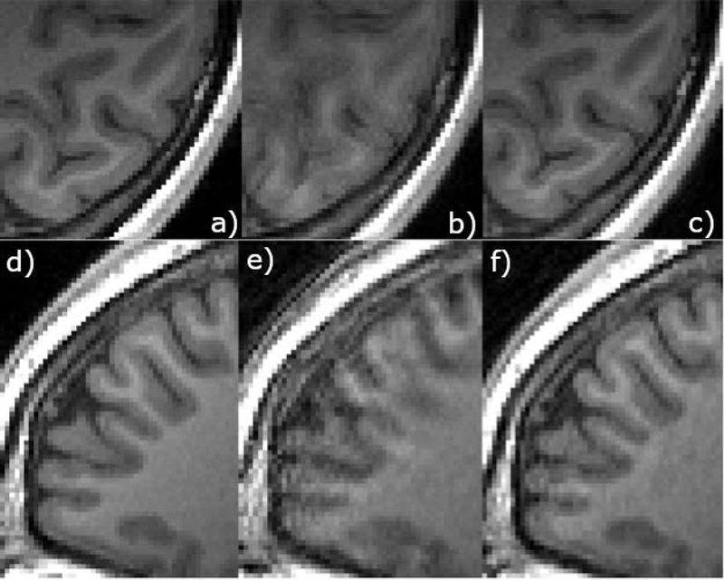
Figure 5 shows sample images from a volunteer motion experiment (abrupt movement). Images on the left show axial and sagittal views from the no motion scan. The middle column shows images acquired with four abrupt motions with no correction applied, and the right column shows the results of the retrospective correction algorithm applied to this dataset. The third row shows difference images of the motion scan, taking the no motion scan as the ground truth. Figure 6 shows zoomed in regions from an axial slice (top) and sagittal slice (bottom) from the same experiment as in Figure 5. The motion scan without any correction shows clear blurring and artifacts. Retrospective correction significantly reduced the blurring in the images. Sample results from other motion experiments (nodding, abrupt nodding) are shown in Supporting Information Figures S1 and S2. Motion patterns corresponding to each figure are shown in Supporting Information Figure S3. Motion patterns from all volunteers performing continuous nodding motion are shown in Supporting Information Figure S4 for comparison.
Figure 5.
Motion corrected scans of subject 1 using EM tracker (c,f) is compared against non-corrected scans (b,e) in sagittal (b,c) and axial (e,f) orientations. The bottom row shows the difference image compared to the reference no motion scan (a,d). Retrospective correction resulted in lower errors especially inside the brain.
Figure 6.
Zoomed in images of the axial and sagittal slices from the experiment shown in Figure 5. Retrospective correction resulted in a much better gray matter white matter differentiation.
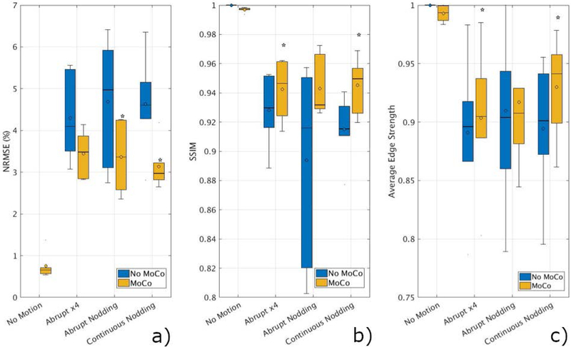
Figure 7 summarizes the results of the volunteer scans. NRMSE and SSIM are averaged over six volunteers for each type of motion. Retrospective correction significantly improved both metrics in all motion types. SSIM increased from 0.91 ± 0.05 (without correction) to 0.96 ± 0.03 with retrospective motion correction using data from the EM tracker. NRMSE reduced from 3.78 ± 1.51% to 2.74 ± 0.11% when motion correction was applied.
Figure 7.
Summary of quantitative results from six volunteer scans. SSIM (a), NRMSE (b) and AES (c) values improved for all the cases compared to the original scans without motion correction. Analysis determined that NRMSE improvements were statistically significant (p<0.05) for abrupt nodding and continuous nodding (denoted by *). SSIM and AES results were statistically significant for abrupt motion and continuous nodding.
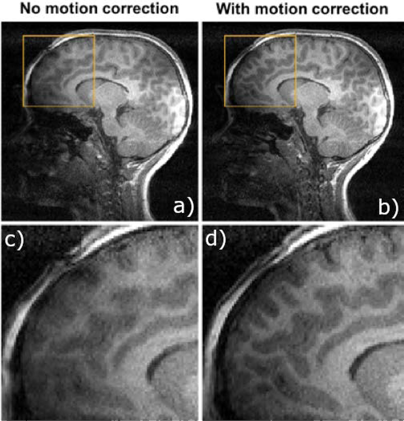
Figure 8 shows sample images from a 7-year-old stroke patient, getting a follow-up MRI scan, where an EM-tracked MPRAGE sequence was acquired. A sagittal view through an image without any correction is shown on the top left, with the retrospectively corrected image shown in the top right panel; zoomed in sections are shown on the bottom panels.
Figure 8.
Motion compensated scans demonstrate substantially lower artifact levels. Seven-year-old stroke patient scanned at 3T MRI for a follow-up MRI. Uncorrected (a) and retrospectively corrected (b) MPRAGE using EM tracking motion measurements in a pediatric patient; zoomed in sections (c,d) show reduced blurring and improved gray/white matter differentiation.
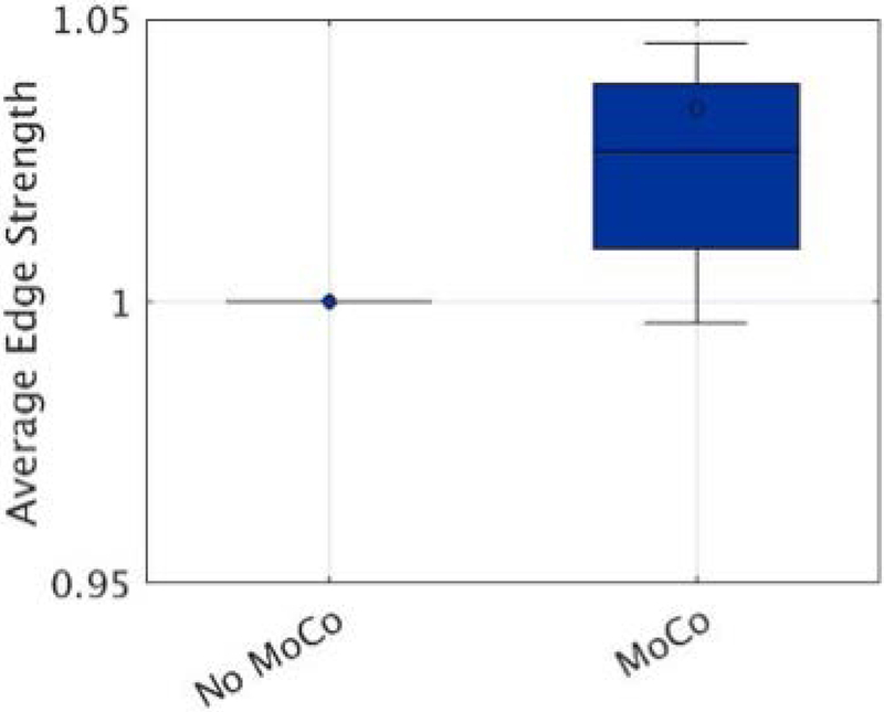
Figure 9 shows the improvement in AES when motion correction was applied retrospectively to the patient data. Normalized AES improved significantly (P<0.05) compared to the no motion correction scans. The mean improvement in average edge strength was 3.7% ± 1.2%.
Figure 9.
Average edge strength (AES) calculated on eight pediatric patients without and with motion correction applied. For each patient, AES was normalized using the uncorrected scan. Motion correction improved AES significantly compared to no motion correction scans, with a mean improvement of 3.7%.
DISCUSSION
Phantom studies show that the EM tracker has excellent accuracy, on the order of 200 microns, when tested in an inter-scan motion scenario. Retrospective correction using EM tracker data improved the image quality both qualitatively and quantitatively in all motion corrupted scans in volunteers and patients. The data included motions up to 7 mm of translation and 5° of rotation.
Some remaining ghosting artifacts can be seen in the corrected images, i.e. Figures 6 and 8. One reason for these artifacts is the non-rigid motion of regions with fatty tissue. A fat suppression (or water excitation) strategy would be useful in reducing these artifacts. We did not pursue such a strategy as we wanted to match the clinical MPRAGE acquired at our institute. Another potential cause is data corruption and k-space gaps due to large and fast motion. For rotational motion larger than 5°, a density compensation or parallel reconstruction strategy could be helpful to reduce the effect of k-space gaps. A reacquisition strategy would possibly improve the results when the data is corrupted due to motion during readout blocks.
As shown in Supporting Information Figure S5, although the image quality improvement (i.e NRMSE and SSIM) is higher for scans with larger total motions (motion score calculated using Jenkinson et al. [28]), the image quality of the retrospectively corrected image also decreases with increasing motion. Therefore, we limited the motions to 5° and 5 mm. The images shown in Figure 5, Supporting Information Figures S1 and S2 correspond to motion scores of 0.12mm, 0.26mm and 0.18mm, consecutively. Motion scores were calculated as mean displacement in each brain volume, modelled as a sphere of radius 65 mm.
Remaining challenges include the sensor placement on the head and the effects of skin motion and non-rigid motion, which need to be considered to further improve image quality. In this work, we used multiple sensors attached on a headband. For all of the adult volunteers scanned in this study, the size of the sensor was not an issue. It is possible that for a person with larger head-size, the sensor might not fit into a head coil. It is possible to miniaturize the device by printing the coils on a circuit board. The accuracy of such a system will be investigated in future work. As with any external motion tracking device attached to the head, it is possible that the headband could move independently from the brain, resulting in a reduced image quality. In all the experiments reported in this manuscript, the image quality improved compared to the no correction scans suggesting that this was not an issue. Although there have been other solutions suggested in literature such as mouth-pieces [29], we found that the adaptation of these kind of strategies is highly challenging in pediatric subjects.
For this work we assumed that GRAPPA coefficients can be reliably estimated from uncorrected data since the motions are small. This assumption may fail to hold if the subject moves during the acquisition of GRAPPA autocalibration lines. One possible solution to improve the results in these cases would be reacquisition of the GRAPPA autocalibration lines, or a separate acquisition of coil sensitivities with an augmented SENSE reconstruction [30]. The effect of motion on the coil sensitivities or the GRAPPA kernel will be investigated in future work. Also as motion measurements are not available for the non-acquired lines in the final reconstruction, motion values were interpolated from the neighboring acquired lines.
In this work, we have evaluated the efficacy of the motion tracking only with the MPRAGE sequence. EM tracking systems can be used with many imaging sequences currently being employed in clinical studies. Currently the system requires additional gradient blips in Gx,Gy and Gz. In sequences with little or no dead time (e.g. in bSSFP/TrueFISP) adding blips may introduce undesirable flow or spin history effects). The system can also be used with the native gradients of a sequence as most imaging sequences already have these kinds of gradients used as imaging gradients. It is also possible to reduce the duration of the gradient blips. The accuracy of the system using the native gradients and shorter gradient blips will be investigated in future work. One limitation of the sensors is vulnerability to eddy currents. This was not a problem for this study as the MPRAGE sequence has lots of dead time. For sequences like diffusion weighted MRI, the location of the activation gradients should be carefully selected to minimize eddy current effects. The system also currently uses a fiber-optic cable to transfer the induced voltage information to the system computer. A wireless solution would further improve the clinical acceptance of the system workflow.
There has been other work that uses the changes in the measured gradients to estimate motion [31–34]. A recent work [35] proposed using a similar design of pickup coils with a magnetometer to estimate motion parameters, uses a wireless radio frequency triggered acquisition orientation of the sensor, but results in a larger device size. The clinical feasibility of such a device for safety and field inhomogeneity disturbance should be investigated in future work.
For this work the raw k-space data was saved into an external computer and reconstructed offline. After the GRAPPA kernel was calculated, each coil image took around 90 seconds to reconstruct, which can be parallelized to reduce the overall scan reconstruction time. Total reconstruction time was less than 5 minutes on an Intel Xeon E5–2680 2.70GhZ workstation with 256GB of RAM. In future, the reconstruction will be integrated into the scanner reconstruction framework.
Currently the retrospective correction method was tested on the 3D MPRAGE sequence. It can be easily extended to any 3D sequence such as 3D SPACE or 3D GRE. Due to the inability of the reconstruction algorithm to correct for through-plane motion in 2D sequences, prospective correction is expected to give better results for 2D sequences.
CONCLUSIONS
We have described an electromagnetic tracker based motion measurement system and retrospective correction using these measurements in a clinical anatomical MRI sequence. We demonstrated that the EM tracker measures motion with high accuracy and precision, and that EM tracking based motion correction improves the image quality in both volunteer scans with deliberate motion, and in pediatric patients, who have a high propensity to move within the scanner. As the motion tracker uses changes in the magnetic field to measure motion parameters, it can be used in scenarios where line-of-sight is limited. Future work will test the system using prospective motion correction in pediatric populations in clinical practice.
Supplementary Material
Supporting Information Figure S1: Motion corrected scans of subject 1 performing continuous nodding. Corrected images using EM tracker measurements (c,f) are compared against non-corrected scans (b,e) in sagittal (top) and coronal (bottom)
Supporting Information Figure S2: Motion corrected scans of subject 1 performing abrupt nodding. Corrected images using EM tracker measurements (c,f) are compared against non-corrected scans (b,e) in sagittal (top) and coronal (bottom) orientations. Retrospective correction resulted in substantially improved image quality.
Supporting Information Figure S3: Sample motion patterns from a volunteer showing the motion traces from a) abrupt motion b) abrupt nodding c) continuous nodding.
Supporting Information Figure S4: Sample motion patterns from 6 volunteers for the continuous nodding motion. The case shown in Supporting Information Figure S1 corresponds to the motion pattern in Supporting Information Figure S4.c.
Supporting Information Figure S5: The relationship between the amount of motion and image quality (SSIM and RMSE) with and without motion correction for all 6 subjects. We have used total displacement (Jenkinson et al) as a metric for total motion for this figure. The examples from the manuscript correspond to motion scores of 0.12 for abrupt motion, 0.18 for abrupt nodding motion and 0.26 for nodding motion.
ACKNOWLEDGEMENTS
This research was supported in part by NIH grants R01 NS079788, R01 EB019483, R01 DK100404, R44 MH086984, IDDRC U54 HD090255, and by a research grant from the Boston Children’s Hospital Translational Research Program.
REFERENCES
- 1).Andre JB, Bresnahan BW, Mossa-Basha M, Hoff MN, Smith CP, Anzai Y and Cohen WA, 2015. Toward quantifying the prevalence, severity, and cost associated with patient motion during clinical MR examinations. Journal of the American College of Radiology, 12(7), pp.689–695. [DOI] [PubMed] [Google Scholar]
- 2).Afacan O, Erem B, Roby DP, Roth N, Roth A, Prabhu SP and Warfield SK, 2016. Evaluation of motion and its effect on brain magnetic resonance image quality in children. Pediatric radiology, 46(12), pp.1728–1735. [DOI] [PMC free article] [PubMed] [Google Scholar]
- 3).Malviya S, Voepel-Lewis T, Eldevik OP, Rockwell DT, Wong JH and Tait AR, 2000. Sedation and general anaesthesia in children undergoing MRI and CT: adverse events and outcomes. British journal of anaesthesia, 84(6), pp.743–748. [DOI] [PubMed] [Google Scholar]
- 4).Edwards AD and Arthurs OJ, 2011. Paediatric MRI under sedation: is it necessary? What is the evidence for the alternatives?. Pediatric radiology, 41(11), p.1353. [DOI] [PubMed] [Google Scholar]
- 5).Pipe JG, 1999. Motion correction with PROPELLER MRI: application to head motion and free-breathing cardiac imaging. Magnetic Resonance in Medicine: An Official Journal of the International Society for Magnetic Resonance in Medicine, 42(5), pp.963–969 [DOI] [PubMed] [Google Scholar]
- 6).Welch EB, Rossman PJ, Felmlee JP and Manduca A, 2004. Self-navigated motion correction using moments of spatial projections in radial MRI. Magnetic Resonance in Medicine: An Official Journal of the International Society for Magnetic Resonance in Medicine, 52(2), pp.337–345 [DOI] [PubMed] [Google Scholar]
- 7).Feng L, Axel L, Chandarana H, Block KT, Sodickson DK and Otazo R, 2016. XD-GRASP: golden-angle radial MRI with reconstruction of extra motion-state dimensions using compressed sensing. Magnetic resonance in medicine, 75(2), pp.775–788 [DOI] [PMC free article] [PubMed] [Google Scholar]
- 8).Glover GH and Lai S, 1998. Self-navigated spiral fMRI: interleaved versus single-shot. Magnetic resonance in medicine, 39(3), pp.361–368 [DOI] [PubMed] [Google Scholar]
- 9).White N, Roddey C, Shankaranarayanan A, Han E, Rettmann D, Santos J, Kuperman J and Dale A, 2010. PROMO: real-time prospective motion correction in MRI using image-based tracking. Magnetic Resonance in Medicine: An Official Journal of the International Society for Magnetic Resonance in Medicine, 63(1), pp.91–105 [DOI] [PMC free article] [PubMed] [Google Scholar]
- 10).Van Der Kouwe AJ, Benner T and Dale AM, 2006. Real-time rigid body motion correction and shimming using cloverleaf navigators. Magnetic Resonance in Medicine: An Official Journal of the International Society for Magnetic Resonance in Medicine, 56(5), pp.1019–1032 [DOI] [PubMed] [Google Scholar]
- 11).Welch EB, Manduca A, Grimm RC, Ward HA and Jack CR Jr, 2002. Spherical navigator echoes for full 3D rigid body motion measurement in MRI. Magnetic Resonance in Medicine: An Official Journal of the International Society for Magnetic Resonance in Medicine, 47(1), pp.32–41. [DOI] [PubMed] [Google Scholar]
- 12).Kober T, Marques JP, Gruetter R and Krueger G, 2011. Head motion detection using FID navigators. Magnetic resonance in medicine, 66(1), pp.135–143 [DOI] [PubMed] [Google Scholar]
- 13).Wallace TE, Afacan O, Waszak M, Kober T and Warfield SK, 2019. Head motion measurement and correction using FID navigators. Magnetic resonance in medicine, 81(1), pp.258–274 [DOI] [PMC free article] [PubMed] [Google Scholar]
- 14).Tisdall MD, Hess AT, Reuter M, Meintjes EM, Fischl B and van der Kouwe AJ, 2012. Volumetric navigators for prospective motion correction and selective reacquisition in neuroanatomical MRI. Magnetic resonance in medicine, 68(2), pp.389–399 [DOI] [PMC free article] [PubMed] [Google Scholar]
- 15).Ooi MB, Krueger S, Thomas WJ, Swaminathan SV and Brown TR, 2009. Prospective real-time correction for arbitrary head motion using active markers. Magnetic Resonance in Medicine: An Official Journal of the International Society for Magnetic Resonance in Medicine, 62(4), pp.943–954 [DOI] [PMC free article] [PubMed] [Google Scholar]
- 16).Ooi MB, Aksoy M, Maclaren J, Watkins RD and Bammer R, 2013. Prospective motion correction using inductively coupled wireless RF coils. Magnetic resonance in medicine, 70(3), pp.639–647 [DOI] [PMC free article] [PubMed] [Google Scholar]
- 17).Zaitsev M, Dold C, Sakas G, Hennig J and Speck O, 2006. Magnetic resonance imaging of freely moving objects: prospective real-time motion correction using an external optical motion tracking system. Neuroimage, 31(3), pp.1038–1050 [DOI] [PubMed] [Google Scholar]
- 18).Aksoy M, Forman C, Straka M, Skare S, Holdsworth S, Hornegger J and Bammer R, 2011. Real-time optical motion correction for diffusion tensor imaging. Magnetic resonance in medicine, 66(2), pp.366–378 [DOI] [PMC free article] [PubMed] [Google Scholar]
- 19).Qin L, van Gelderen P, Derbyshire JA, Jin F, Lee J, de Zwart JA, Tao Y and Duyn JH, 2009. Prospective head-movement correction for high-resolution MRI using an in-bore optical tracking system. Magnetic Resonance in Medicine: An Official Journal of the International Society for Magnetic Resonance in Medicine, 62(4), pp.924–934 [DOI] [PMC free article] [PubMed] [Google Scholar]
- 20).Frost R, Wighton P, Karahanoğlu FI, Robertson RL, Grant PE, Fischl B, Tisdall MD and van der Kouwe A, 2019. Markerless high-frequency prospective motion correction for neuroanatomical MRI. Magnetic resonance in medicine. [DOI] [PMC free article] [PubMed] [Google Scholar]
- 21).Roth A, Nevo E, 2010, Method and apparatus to estimate location and orientation of objects during MRI, patent app 20100280353
- 22).Erem B, Afacan O, Gholipour A, Prabhu SP and Warfield SK, 2014. A System Identification Approach to Estimating a Dynamic Model of Head Motion for MRI Motion Correction. In Intelligent MRI Workshop MICCAI. [Google Scholar]
- 23).Gallichan D, Marques JP and Gruetter R, 2016. Retrospective correction of involuntary microscopic head movement using highly accelerated fat image navigators (3D FatNavs) at 7T. Magnetic resonance in medicine, 75(3), pp.1030–1039 [DOI] [PubMed] [Google Scholar]
- 24).Walsh DO, Gmitro AF and Marcellin MW, 2000. Adaptive reconstruction of phased array MR imagery. Magnetic Resonance in Medicine: An Official Journal of the International Society for Magnetic Resonance in Medicine, 43(5), pp.682–690 [DOI] [PubMed] [Google Scholar]
- 25).Wang Z, Bovik AC, Sheikh HR and Simoncelli EP, 2004. Image quality assessment: from error visibility to structural similarity. IEEE transactions on image processing, 13(4), pp.600–612 [DOI] [PubMed] [Google Scholar]
- 26).Smith SM, 2002. Fast robust automated brain extraction. Human brain mapping, 17(3), pp.143–155. [DOI] [PMC free article] [PubMed] [Google Scholar]
- 27).Aksoy M, Forman C, Straka M, Çukur T, Hornegger J and Bammer R, 2012. Hybrid prospective and retrospective head motion correction to mitigate cross-calibration errors. Magnetic resonance in medicine, 67(5), pp.1237–1251 [DOI] [PMC free article] [PubMed] [Google Scholar]
- 28).StuchtD S, DanishadKA K and ZaitsevM A, 2012. Accuracy of prospective motion correction in MRI using tracking markers on repositionable dental impressions. In Medical Image Understanding and Analysis (pp. 223–228) [Google Scholar]
- 29).Jenkinson M, Bannister P, Brady M and Smith S, 2002. Improved optimization for the robust and accurate linear registration and motion correction of brain images. Neuroimage, 17(2), pp.825–841. [DOI] [PubMed] [Google Scholar]
- 30).Bammer R, Aksoy M and Liu C, 2007. Augmented generalized SENSE reconstruction to correct for rigid body motion. Magnetic Resonance in Medicine: An Official Journal of the International Society for Magnetic Resonance in Medicine, 57(1), pp.90–102 [DOI] [PMC free article] [PubMed] [Google Scholar]
- 31).van der Kouwe A et al. 2009. Real-time prospective rigid-body motion correction with the EndoScout gradient-based tracking system Proc. 17th Scientific Meeting ISMRM p 4623 [Google Scholar]
- 32).Vestergaard MB, Schulz J, Turner R and Hanson LG, “Motion tracking from gradient induced signals in electrode recordings”, Proc ESMRMB 2011. [Google Scholar]
- 33).Andersen M, Madsen KH, and Hanson LG, “Prospective motion correction for MRI using EEG-equipment, Proc ISMRM 2016. ”. [Google Scholar]
- 34).Bhuiyan EH, Spencer GS, Glover PM and Bowtell R, “Tracking head movement inside an MR scanner using voltages induced in coils by time-varying gradients”, Proc ISMRM 2017. [Google Scholar]
- 35).van Niekerk A, Meintjes E and van der Kouwe A, 2019. A wireless radio frequency triggered acquisition device (WRAD) for self-synchronised measurements of the rate of change of the MRI gradient vector field for motion tracking. IEEE transactions on medical imaging. [DOI] [PMC free article] [PubMed] [Google Scholar]
Associated Data
This section collects any data citations, data availability statements, or supplementary materials included in this article.
Supplementary Materials
Supporting Information Figure S1: Motion corrected scans of subject 1 performing continuous nodding. Corrected images using EM tracker measurements (c,f) are compared against non-corrected scans (b,e) in sagittal (top) and coronal (bottom)
Supporting Information Figure S2: Motion corrected scans of subject 1 performing abrupt nodding. Corrected images using EM tracker measurements (c,f) are compared against non-corrected scans (b,e) in sagittal (top) and coronal (bottom) orientations. Retrospective correction resulted in substantially improved image quality.
Supporting Information Figure S3: Sample motion patterns from a volunteer showing the motion traces from a) abrupt motion b) abrupt nodding c) continuous nodding.
Supporting Information Figure S4: Sample motion patterns from 6 volunteers for the continuous nodding motion. The case shown in Supporting Information Figure S1 corresponds to the motion pattern in Supporting Information Figure S4.c.
Supporting Information Figure S5: The relationship between the amount of motion and image quality (SSIM and RMSE) with and without motion correction for all 6 subjects. We have used total displacement (Jenkinson et al) as a metric for total motion for this figure. The examples from the manuscript correspond to motion scores of 0.12 for abrupt motion, 0.18 for abrupt nodding motion and 0.26 for nodding motion.


