Abstract
We investigate fluid pathways beneath volcanic lakes using bathymetry and geochemical measurements to locate best-possible drilling sites. Highly permeable structures, such as faults, provide fluid channels that are the most suitable access points to the geothermal resource. Accurate mapping of these structures therefore guides the successful targeting of wells. Lakes, rivers or ocean, can hide surface footprints of these permeable structures, such as in our case beneath Lake Linau. High-resolution bathymetry identifies linear and conical discontinuities, which are linked to offshore tectonic structures as confirmed by surrounding outcrops and hot springs. Geochemical measurements document inflow of hot saline acidic water into the lake verifying bathymetry-located highly permeable structures. Integrating onshore well data, our bathymetry and chemical results locates an ideal drilling site into the geothermal reservoir beneath the western shore line of Lake Linau.
Subject terms: Geology, Tectonics
Introduction
Where to drill? This is the principle question arising when searching for an efficient access to subsurface geo-energy resources. Fluids in geological media flow along highly permeable fluid pathways, which are the key target for geothermal energy. These flow pathways can be faults, fractures or pore-throats. From wellbore, micro-earthquake and core data we know that the flow pathways are spatially correlated permeability structures1. This is true across five orders of magnitude in scale length from cm to km1. Available techniques to locate these structures have to be improved because only ~40% among these geothermal production wells perform above the expected well capacity2.
In geothermal fields, subsurface structural setting is identified by fault traces, hot springs or gas emanations at surface. Fluid discharge is an indicator for highly permeable zones at depth. These zones can be classified based on seismic interpretation of fault related, intrusion related or pipe related systems3. Fluids migrate in these systems bypassing the pore-network and sealing layers. Hot springs occur in specific structural settings along the faults4: at fault terminations, fault overlaps, fault intersections and topographically visible fault traces. The increased permeability is located in the damage zones of these settings5 due to enhanced deformation and instable geometry6. In the Taupo Volcanic Zone, e.g., fluid flow is mainly associated with fault step-overs and their linking faults7. Nevertheless, permeability can even vary within a single fault zone. This is because fault zones consist of two parts: the fault core with lower (matrix) permeability and the damage zone with higher (fracture) permeability8.
Mapping tectonic structures and fluid discharge onshore has been done mainly by structural geological mapping9–12, remote sensing13,14 and/or geophysical measurements15,16. However, using these approaches for offshore structures is not practical due to limited access to sea floor. Here, bathymetry is the most practical approach worldwide. Mapping seafloor morphology and therefore identifying tectonic structures has been done using bathymetry for more than 50 years now17. In the oil and gas industry, bathymetry is a well-proven tool to also detect hydrocarbon seepage at the seafloor18,19. At open sea, large faults have been characterized using this approach, e.g. off Portugal20 and in the Marmara Sea21. Bathymetry allows mapping the underwater morphology22,23, specific faults24,25, caldera structures and mud volcanoes26,27 under water. Furthermore, this approach allows identifying tectonic structures with enhanced fluid discharge under lakes28,29. However, bathymetry has not been yet used for mapping of sea bottom fluid discharge from a geothermal reservoir.
Seepage structures are described as pockmarks in lakes or subsea. Pockmarks are near-circular craters or depressions of various size and depth30,31. Their size range between 1–700 m with a depth range of 1–45 m, being much wider than deep. Pockmarks are known to be associated with fluid discharge, like gas emanations and warm water outflow30,31. Their relation to biological, mineralogical or physicochemical characteristics has been studied at different locations on the earth32, e.g. in Lake Constance they represent collapse structures formed by blown out material33. Pockmarks also show increased temperatures due to discharge of warm fluids34. They can also be controlled by tectonic structures or sea bottom current35.
The study site we chose to test the idea of mapping sea bottom geothermal fluid discharge is at Lahendong, which hosts a producing geothermal field on the Indonesian island of Sulawesi. Previous studies and personal communications with local inhabitants show, that an acidic volcanic lake in the middle of the geothermal field masks faults and fumaroles36,37. Furthermore, the most productive wells in the field penetrate into a reservoir compartment beneath this lake. However, onshore outcrops or hot springs are not sufficient to efficiently characterize the reservoir beneath the lake, which makes it difficult to determine future drilling targets. To tackle this issue, we used bathymetry and geochemical measurements to identify and characterize permeability structures of the geothermal reservoir hidden beneath the lake.
We carried out a ten-day survey on the 600 × 800 m large Lake Linau in the Lahendong geothermal field. The bathymetry survey was carried out using a Lowrance Elite TI 7 from Navico with CHIRP sensor installed on a raft driven in circles towards the middle of the lake. Geochemical measurements were done at 52 locations in the lake using a CastAway-CTD logger from SonTek. Four selected profiles are presented in this paper.
Results from our study show deep holes at the lake bottom. They are linked to known faults from previous studies and newly discovered faults in this study. Lineaments link fault outcrops onshore, hot springs on fault intersections and the deep holes offshore. The deep holes are located at typical ‘fault intersections’4. Geochemical data along and across these faults identify inflow of hot saline acidic water into the deep holes. This leads us to the conclusion that fault compartments have an increased permeability at the deep hole locations. Combining bathymetric and geochemical data, we were able to distinguish between permeable and impermeable fault compartments and relate them to productivity of geothermal wells. Such information is indispensable for a deep understanding of the behavior of the geothermal system and therefore its sustainable usage.
Available Knowledge About The Reservoir Before The 2018 Survey
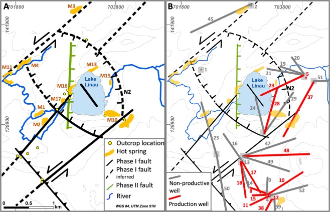
The Lahendong geothermal field (LHD) has been producing steam and brine since 2001. The average permeability of the volcanic reservoir rocks is low with values from 10−14 to 10−15 m2. From 40 wells, 12 hit highly permeable zones and are sufficiently productive. The highest well productivities are from two wells targeting a reservoir beneath the caldera lake Linau. These wells (LHD 23 and LHD 28) produce 240 °C hot brine with a pH of 3 at a flow rate equivalent to 20 MWe. Despite the close proximity, other wells are considerably less productive (Table 1, Fig. 1). This inhomogeneity in production performance is due to a local control on the fluid flow by fractures and faults36,37. Previous geophysical studies, i.e. MT, microearthquakes and gravity, do not resolve fracture or fault locations beneath Lake Linau but rather show e.g. less resistive structures overlain by conductors, interpreted as clay cap above a regional fluid up-flow structure38,39. Therefore, this area lacks a full understanding of fault and permeability distribution especially beneath the lake.
Table 1.
Approximate well productivities in the Lahendong geothermal field.
| Well No | Productivity [MWe] | Well No | Productivity [MWe] | Well No | Productivity [MWe] |
|---|---|---|---|---|---|
| 1 | 0 | 15 | 5 | 29 | 0 |
| 2 | 0 | 16 | 0 | 37 | 3 |
| 4 | 7 | 17 | 7 | 38 | 7 |
| 5 | 5 | 18 | 7 | 39 | 0 |
| 8 | 5 | 19 | 0 | 45 | 0 |
| 9 | 0 | 20 | 0 | 47 | 7 |
| 10 | 5 | 21 | 0 | 48 | 7 |
| 11 | 5 | 23 | 20 | 49 | 0 |
| 12 | 5 | 24 | 0 | 50 | to be tested |
| 13 | 0 | 25 | 0 | 51 | to be tested |
| 14 | 0 | 28 | 20 |
Figure 1.
Fault set-up in the Lahendong geothermal field, outcrop and well locations before 2018.
A priori knowledge on faults before the 2018 survey
Location of faults in the Lahendong geothermal field have been investigated in a number of previous studies36,37,40–42. Most obvious indicators for faults are their appearance in outcrops, topographical steps in the field and well data on geochemistry, productivity and temperature. Hot springs often occur at intersections of faults, validating them as additional indicators for faults37.
The tropical environment of Lahendong with dense vegetation and high alteration rates allows only rare access to outcrops with fresh hard rock. However, data from 40 wells show indications for faults through strong differences in geochemical fluid properties, productivities and temperatures in close distance. Mainly two geochemical types of fluids are produced from wells, i.e. one highly saline (5–10 mS/cm) and one less saline (1 mS/cm). Wells producing highly saline fluids from below Lake Linau (LHD23, LHD28) are located only 300 m from a well producing low saline fluid (LHD5) (Fig. 1). An impermeable fault (N2) prevents mixing between those fluids at depth. Also, high productive wells and less or non-productive wells are in close distance but separated by faults: While LHD 23 produces 20 MWe, LHD 19 is non-productive similar to the non-productive LHD 24 close to LHD 28 producing 20 MWe (Table 1, Fig. 1). Additionally, temperature data from wells show strong drops from 310 °C to 160 °C across the fault N2 from LHD 23 to LHD 5, indicating a cold intrusion through vertical permeability in the fault. Thus, faults in the Lahendong area can be horizontally impermeable but permeable in vertical direction independent of fault type.
A comparison of fault locations with hot springs in the Lahendong area show that hot springs occur at typical structural settings4 (Fig. 1), i.e. fault tips (M11), fault intersections (M4, M10, M16) and along fault traces (M2, M3). Hot springs, which do not show a clear link to faults are assumed to be sitting on hidden faults.
The combination of previous knowledge on fault location and type suggests two faulting phases in the Lahendong area (Fig. 1). The relatively older one (Phase I) is situated in a stress field with horizontal σ1~355°. In this system, strike-slip faults strike 40° and have a left lateral movement also according to outcrop observations, e.g. slickensides. Step-over zones are observed, creating thrust faults at a right step-over and normal faults at a left step-over. This stress field is generated by two subduction zones pushing below North-Sulawesi from north and south. A second faulting phase (Phase II) is caused by upwelling of the regional crust due to heating and nearby volcanism. This stress-field with a vertical σ1 creates N-S or E-W oriented normal faults. Normal faults in both systems dip 70–90°, while thrust faults dip with ~40° and strike-slip faults are nearly vertical.
In spite of this comprehensive knowledge, the geothermal exploitation area especially beneath Lake Linau is lacking a detailed understanding of fault orientations and their permeability behavior. The reservoir beneath Lake Linau is still a blank area but of special interest because of its high productivity and exceptional fluid composition (highly saline and highly acidic), which brings challenges for a sustainable production.
The results of the study we report here clarify most of the open questions related to the poorly understood variability in the productivity of geothermal wells and brings a detailed picture of the reservoir beneath Lake Linau including new target zones for wells.
Methods
Bathymetry
Bathymetry has been done using a Lowrance Elite TI 7 from Navico. The tool consists of a CHIRP (Compressed High Intensity Radar Pulse) sonar, GPS navigation and a multibeam echosounder with side-scan and down-scan imaging. The down-scan detects the depth at a single point and the side-scan captures information and views at each side of the boat.
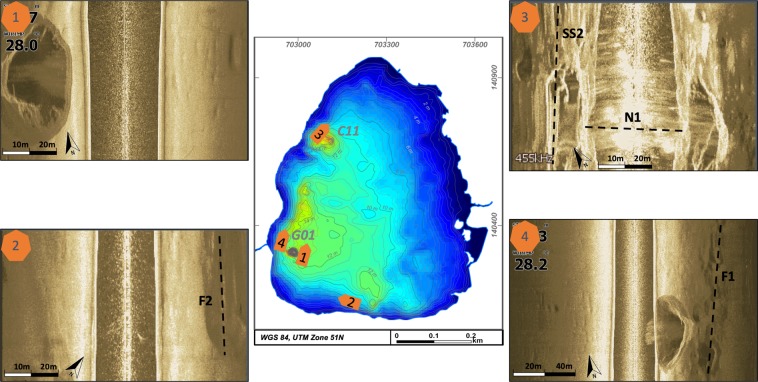
Circles driven on the lake have a distance of 40 m and add up to a total length of 16.5 km, which is equal to 15,000 measurement points (Fig. 2).
Figure 2.
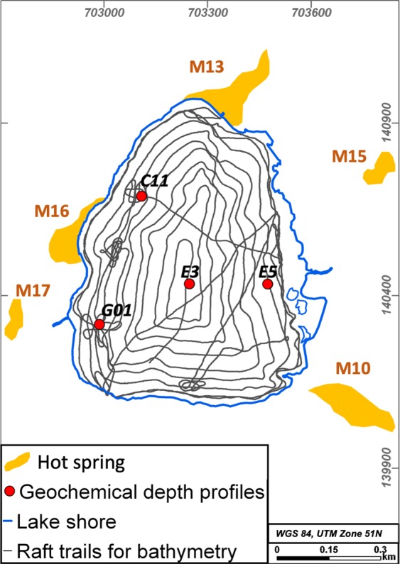
Measurement set-up for bathymetry driven by the raft and geochemical depth profiles at sampling locations G01, C11, E3, E5 and hot spring locations.
Instruments have been installed on a raft going in spirals on the lake with decreasing diameter to the lake center and a distance of approximately 40 m between the consecutive rounds. Certain areas were crossed with an additional finer mesh to get a more detailed data set.
Thereafter, data have been processed and transformed to x-y-z coordinates by Kriging analysis using ReefMaster by ReefMaster Software Ltd. Processed depth data achieve an accuracy of 0.5 m. 3D views of bathymetry data and fault locations have been achieved by self-written codes in Matlab.
Geochemical depth profiles
Chemical profiles have been logged using the CastAway-CTD logger from SonTek. The logger includes sensors for conductivity, density, temperature, pressure and GPS. It allows sampling at a 5 Hz sampling rate up to 100 m depth, translated to 15 cm sampling distance.
52 spots were sampled across the lake at 100 m distance from a raft on the lake. Three to four logs were run consecutively at the same spot. Logging is done while lowering the probe to the lake bottom and lifting it again with approximately 1 m/s. Sampling spots presented in this paper are two deep holes in the west, one spot in the center of the lake and one spot at the eastern shore of the lake (Fig. 2). The selected spots represent two geochemically extreme pattern (G01, E3, E5) and one average pattern (E3) for this lake. Logs presented for one single spot show the most representative average pattern for that location. The whole dataset of 52 spots is topic of a subsequent manuscript in progress.
Data were extracted from the instrument using Castaway-CTD Software by SonTek. Plots of geochemical depth profiles were constructed from self-written codes in Matlab.
Results
Bathymetry
This is the first reported bathymetry survey for Lake Linau. Before, the depth of the lake was estimated to 10–12 m43. Its total depth ranges from 0.5 to 35 m. In general, the northern and eastern parts of the lake are shallower, with <10 m. Here, the lake bottom dips with ~2° towards the southwest. The southern and western parts dip with ~10° and have a maximum depth of 14 m (Fig. 3).
Figure 3.
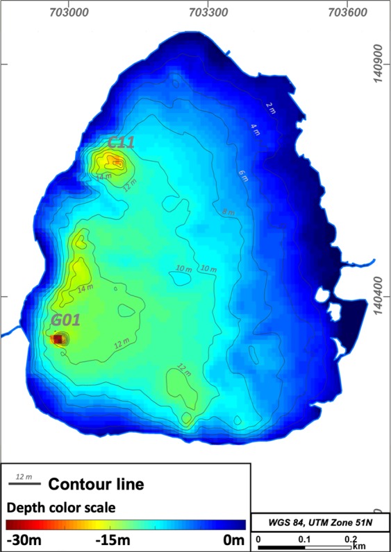
Bathymetry depth map of Lake Linau.
The main discovery of the survey were two 22 m and 35 m deep holes at the lake bottom near the western shore. The holes have a diameter of 20–40 m at the top and 4 m at the bottom, which indicates a slope of the conical walls of 34°. Side-scan images show that the holes are not filled by lake sediments and the walls are built up of the surrounding bedrock. In between the two deepest holes the lake bottom has several 14 m deep elliptical structures sitting on an alignment striking N-S. Further round-shaped depressions are 12 m deep in the southern part of the lake (Figs 3 and 4). We traversed the deeper structures several times with a denser net of raft trails to map them in more detail.
Figure 4.
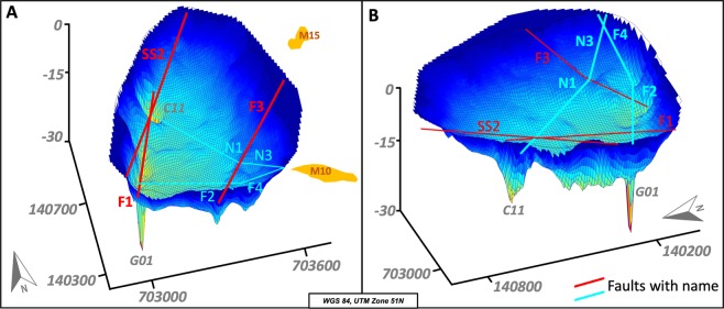
3D bathymetry of Lake Linau, (A): view from SW, (B): view from SE, vertical exaggeration ~10.
Side-scan images show the hole structures and lineaments at the lake bottom (Fig. 5). The deepest hole (locations 1 & 4) is imaged from east and west. The image shows the strongly dipping conical walls. At C11 the image is less clear but still shows the hole structure. The lake bottom here is covered by soft sediment (light ground color) transported in from hot spring discharge and surrounding alterations at M16. At location 2 a linear element is visible to the NE, which is assumed to be a fault structure. Also, at location 3 and 4 structures on the lake ground are visible related to fault lineaments shown in Fig. 6.
Figure 5.
Side scan images from the lake bottom showing hole structures (1,3,4) and fault patterns (2).
Figure 6.
3D bathymetry with newly discovered faults and their names, vertical exaggeration ~20.
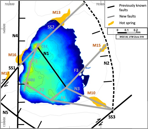
Especially the 3D presentation of the bathymetry data show lineaments at the lake bottom, assumed to be fault traces (Fig. 6). The two deepest holes and depressions in between sit on the most obvious lineament striking NNE-SSW (F1). In the deep hole C11, F1 meets with the strike-slip fault SS1 and the normal fault N1. In the eastern part, the lake bottom shows topographic break-offs and deeper round-shaped structures in alignment with hot spring M15 striking NE-SW (F3). G01 is the intersection point of two lineaments (F1, F2) striking NE-SW and NW-SE. F2 crosses depressions in the southern lake area and continues as F4 towards hot spring M10 onshore where it meets with N3. N3 is the connection line between the previously known fault N1 and M10 onshore. N3 and N1 meet at the break-off point in the eastern lake part.
Geochemical depth profiles
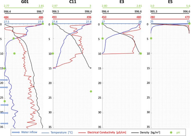
We also took geochemical measurements along a systematic grid of points with 100 m spacing across the lake. They include profiles of temperature, electrical conductivity, density and pH with depth. Here, we report measurements from the deep holes in the west (G01-35 m, C11-15 m), a profile in the middle of the lake (E3-10 m) and a location in the eastern shallow area (E5-3 m) (Fig. 7).
Figure 7.
Geochemical depth profiles at selected locations in Lake Linau.
All temperature profiles show a strong decrease down to 5 m followed by a moderate decrease down to 15 m (Fig. 7). Below 15 m, the temperature increases. Moreover, below 15 m the temperature pattern is unstable and shows several peaks. Temperature peaks are an indication for inflow of warmer water.
Electrical conductivity generally decreases to a minimum within the top 5 m (Fig. 7). Between 5 and 15 m it slightly increases. The relatively strong decrease in C11 between 10 and 15 m can be explained by the anomalous high electrical conductivity in the top 10 m which is caused by inflow of highly saline water from hot springs. In general, the conductivity pattern is less constant than the temperature. Below 15 m, it shows parallel peaks to the temperature. This pattern cannot be explained by temperature increase only, which relates a 1 °C warming to 2% electrical conductivity increase44. That suggests that the warm inflowing water is also highly saline. Assuming an electrical conductivity increase caused only by temperature would lead to 60% smaller peaks.
Density constantly increases with depth at all locations. It shows a change in gradient from a weaker to a stronger increase below 5 m. The density pattern gets less constant and shows slight peaks at depth below 15 m (Fig. 7).
pH has been measured each five or ten meters over depth (Fig. 7). The most neutral pH (5.6) has been measured in the east at the lake surface and is related to river inflow near E5. The pH then decreases to the average lake pH. In the middle of the lake at E3 and at C11 pH increases with depth. This behavior is related to inflow from onshore acidic hot springs into the shallow layers of the lake at this location. The decrease in pH in the deep hole G01 over depth indicates acidic water inflow from the hole into the lake. Five different inflow zones can be located in the temperature and electrical conductivity pattern over depth (19 m, 21 m, 27 m, 30 m, 34 m) and are possibly due to fractured areas in the bedrock.
Discussion
Our results show that combining bathymetry and geochemical measurements, in our case, is a successful approach to characterize hidden structures beneath lakes. Bathymetry uncovered deep hole structures and geochemical measurements show warm, saline, acidic fluid inflow through these holes. Our study site lies in a tectono-volcanic active environment where the deep hole structures could be volcanic vents, permeable pipe structures, pockmarks or fault intersection points.
The lake bottom topography combined with outcrop data and hot spring locations shows fault traces and their intersection points. We were able to generate a detailed fault map for the Lake Linau area, where four known faults have been confirmed (SS1, N1, N2, N4) and five new faults have been discovered (SS2, N3, F1, F2, F3, F4) (Fig. 8). The 3D view shows that fault lineaments intersect where the bathymetry shows deep depressions in the lake or where hot springs occur onshore.
Figure 8.
Newly discovered faults beneath Lake Linau using bathymetry in this study.
The most obvious lineament in the bathymetry data is connecting the deep holes in the western part of Lake Linau (F1). In the south-west a strike-slip fault (SS1) connects two hot springs onshore (M16, M17). This strike-slip fault continues towards north-east (SS2) and intersects with a NW-SE trending normal fault (N1) at the northern deep hole (C11). The strike-slip fault (SS2) builds a connection between M16, M13 and the deep hole C11 and meets with the northern border of the extension basin (N2). An extension of the normal fault N1 (i.e. N3) merges with a newly discovered fault in the south (F4) and the normal fault N2. At the deepest hole of Lake Linau (G01) a newly discovered fault F2 intersects with the normal fault N4 striking N-S. Another previously unknown fault (F3) strikes SW-NE from a deeper point in the south of Lake Linau towards a hot spring east of Lake Linau (M15), where it meets the normal fault N2 defining the northern border of an extension basin (Fig. 8).
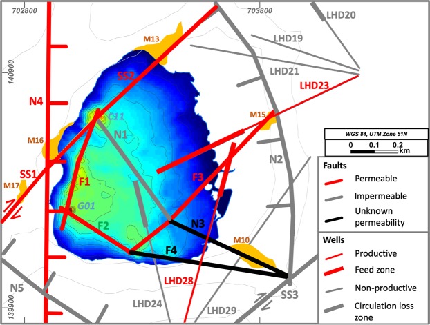
Combining this fault dataset with geochemical profiles in the lake, hot spring locations onshore and production data from wells we were able to distinguish permeable and impermeable sections of faults. Highly productive wells and hot springs near faults as well as inflow at deep holes into the lake and fault intersections in general are indicators for high permeability. In Fig. 9 red faults define highly permeable areas, while grey shows impermeable fault compartments.
Figure 9.
Fault permeability pattern in the Lake Linau area.
Well LHD 23 and LHD 28 are located in a highly permeable reservoir compartment near F3 and show high productivities of 20 MWe. LHD 28 even hits the permeable fault zone F3 at 1850 m depth. Another highly productive area for wells, not targeted yet, is expected near to the deep hole G01. SS1 and SS2 are assumed to be permeable because of hot spring discharge along the faults onshore and fluid inflow into the lake from the deep hole C11. Especially at the intersection on SS1 and N4 excessive hot spring discharge is observed. F1 and F2 are assumed to be permeable because they connect several locations with fluid discharge at the lake bottom (between G01 and C11).
However, some fault intersections do not show fluid inflow into the lake. This can be due to missing measurements or due to certain permeability dynamics, where fluid pathways clog, e.g. by tectonic activity or rock alteration and scaling45. N1, N2, N5 and SS3 are labeled impermeable based on results from previous studies, where they act as geochemical and hydraulic boundary between reservoir compartments36,46. Their appearance is associated with non-productive wells (LHD 19, LHD 21, LHD 24, LHD 29).
Our results show that bathymetric data linked with geochemical measurements allows the development of conceptual geological 3D model of the subsurface. The model includes fault locations and permeability distribution beneath the lake. For the first time it is possible to locate permeable sections of faults and link them to geothermal reservoir characteristics using bathymetry and geochemistry. This technique is not limited to geothermal reservoir characterization but has a wide applicability for subsurface utilization, e.g. structural geological mapping or subsurface storage.
Acknowledgements
We thank Pertamina Jakarta and Pertamina Geothermal Energy Lahendong for their support during field work and permission to enter the geothermal field. Special thanks to GFZ Section 5.2 for borrowing field instruments. Micha helped us with the organization onsite especially the raft. Thanks to D. Bruhn for valuable discussions and for reviewing the manuscript, which highly improved it. F. Bulut´s review in terms of content and language improvement of the manuscript is highly appreciated and constantly improved the manuscript. This study was funded thanks to the Helmholtz-Center Potsdam - GFZ internal expedition budget.
Author contributions
M.B. was the scientific leader of the expedition, did the geochemical analysis and led the preparation of the paper. R.G. operated the bathymetry measurements and did the related data processing. L.S. performed geochemical measurements and Y.K. helped organizing the survey and gave access to well data and interpreted them.
Data availability
Data and computer codes used to analyze the data in this study are available from the corresponding author on request.
Competing interests
The authors declare no competing interests.
Footnotes
Publisher’s note Springer Nature remains neutral with regard to jurisdictional claims in published maps and institutional affiliations.
References
- 1.Leary, P., Malin, P., Saarno, T. & Kukkonen, I. Prospects for assessing enhanced geothermal system (EGS) basement rock flow stimulation by wellbore temperature data. Energies10 (2017).
- 2.IFC. Success of geothermal wells: A global study. IFC, International Finance Corporation, World Bank Group at, http://bit.ly/29SiSfm (2013).
- 3.Cartwright J, Huuse M, Aplin A. Seal bypass systems. Am. Assoc. Pet. Geol. Bull. 2007;91:1141–1166. [Google Scholar]
- 4.Curewitz D, Karson Ja. Structural settings of hydrothermal outflow: Fracture permeability maintained by fault propagation and interaction. J. Volcanol. Geotherm. Res. 1997;79:149–168. doi: 10.1016/S0377-0273(97)00027-9. [DOI] [Google Scholar]
- 5.Peacock DCP, Dimmen V, Rotevatn A, Sanderson DJ. A broader classification of damage zones. J. Struct. Geol. 2017;102:179–192. doi: 10.1016/j.jsg.2017.08.004. [DOI] [Google Scholar]
- 6.Gartrell A, Zhang Y, Lisk M, Dewhurst D. Fault intersections as critical hydrocarbon leakage zones: Integrated field study and numerical modelling of an example from the Timor Sea, Australia. Mar. Pet. Geol. 2004;21:1165–1179. doi: 10.1016/j.marpetgeo.2004.08.001. [DOI] [Google Scholar]
- 7.Rowland JV, Sibson RH. Structural controls on hydrothermal flow in a segmented rift system, Taupo Volcanic Zone, New Zealand. Geofluids. 2004;4:259–283. doi: 10.1111/j.1468-8123.2004.00091.x. [DOI] [Google Scholar]
- 8.Caine JS, Evans JP, Forster CB. Fault zone architecture and permeability structure. Geology. 1996;24:1025–1028. doi: 10.1130/0091-7613(1996)024<1025:FZAAPS>2.3.CO;2. [DOI] [Google Scholar]
- 9.Faulds, J. E., Coolbaugh, M., Bouchot, V., Moek, I. & Oguz, K. Characterizing structural controls of geothermal reservoirs in the Great Basin, USA, and Western Turkey: Developing successful exploration strategies in extended. Proc. World Geotherm. Congr. 25–29 at, http://hal.archives-ouvertes.fr/hal-00495884/ (2010).
- 10.Lynne, B. Y. Siliceous sinter: an early exploration tool and direct link to a geothermal reservoir. Thirty-Eight Work. Geotherm. Reserv. Eng. 1–6 (2013).
- 11.Aubert M, Baubron JC. Identification of a hidden thermal fissure in a volcanic terrain using a combination of hydrothermal convection indicators and soil-atmosphere analysis. J. Volcanol. Geotherm. Res. 1988;35:217–225. doi: 10.1016/0377-0273(88)90018-2. [DOI] [Google Scholar]
- 12.Voltattorni, N., Sciarra, A. & Quattrocchi, F. The Application of Soil-Gas Technique to Geothermal Exploration: Study of Hidden Potential Geothermal Systems. In Proceedings World Geothermal Congress 2010 Bali, Indonesia, 25–29 April 2010 6 p (2010).
- 13.van der Meer FD, et al. Multi- and hyperspectral geologic remote sensing: A review. Int. J. Appl. Earth Obs. Geoinf. 2012;14:112–128. doi: 10.1016/j.jag.2011.08.002. [DOI] [Google Scholar]
- 14.Tralli DM, Blom RG, Zlotnicki V, Donnellan A, Evans DL. Satellite remote sensing of earthquake, volcano, flood, landslide and coastal inundation hazards. ISPRS J. Photogramm. Remote Sens. 2005;59:185–198. doi: 10.1016/j.isprsjprs.2005.02.002. [DOI] [Google Scholar]
- 15.Harinarayana T, et al. Exploration of geothermal structure in Puga geothermal field, Ladakh Himalayas, India by magnetotelluric studies. J. Appl. Geophys. 2006;58:280–295. doi: 10.1016/j.jappgeo.2005.05.005. [DOI] [Google Scholar]
- 16.Garg SK, Pritchett JW, Wannamaker PE, Combs J. Characterization of geothermal reservoirs with electrical surveys: Beowawe geothermal field. Geothermics. 2007;36:487–517. doi: 10.1016/j.geothermics.2007.07.005. [DOI] [Google Scholar]
- 17.Pratson LF, Edwards MH. Introduction to advances in seafloor mapping using sidescan sonar and multibeam bathymetry data. Mar. Geophys. Res. 2004;18:601–605. doi: 10.1007/BF00313876. [DOI] [Google Scholar]
- 18.Tasianas A, et al. High-resolution 3D seismic study of pockmarks and shallow fluid flow systems at the Snøhvit hydrocarbon field in the SW Barents Sea. Mar. Geol. 2018;403:247–261. doi: 10.1016/j.margeo.2018.06.012. [DOI] [Google Scholar]
- 19.MacDonald IR, Sager WW, Peccini MB. Gas hydrate and chemosynthetic biota in mounded bathymetry at mid-slope hydrocarbon seeps: Northern Gulf of Mexico. Mar. Geol. 2003;198:133–158. doi: 10.1016/S0025-3227(03)00098-7. [DOI] [Google Scholar]
- 20.Gracia E, Danobeitia JJ, Verges J, Team P. Mapping active faults offshore {Portugal} (36{N}-38{N}): {Implications} for seismic hazard assessment in the {SW} {Iberian} {Margin} Geology. 2003;31:83–86. doi: 10.1130/0091-7613(2003)031<0083:MAFOPN>2.0.CO;2. [DOI] [Google Scholar]
- 21.Pichon, X. L et al. The active Main Marmara Fault. Earth Planet. Sci. Lett. 192 (2001).
- 22.Newhall CG, et al. Recent geologic history of lake Atitlán, a caldera lake in western Guatemala. J. Volcanol. Geotherm. Res. 1987;33:81–107. doi: 10.1016/0377-0273(87)90055-2. [DOI] [Google Scholar]
- 23.Bacon CR, et al. Morphology, volcanism, and mass wasting in Crater Lake, Oregon. Bull. Geol. Soc. Am. 2002;114:675–692. doi: 10.1130/0016-7606(2002)114<0675:MVAMWI>2.0.CO;2. [DOI] [Google Scholar]
- 24.Gürbüz A, Gürer ÖF. Tectonic geomorphology of the north anatolian fault zone in the Lake Sapanca basin (eastern Marmara Region, Turkey) Geosci. J. 2008;12:215–225. doi: 10.1007/s12303-008-0022-9. [DOI] [Google Scholar]
- 25.Cuylaerts M, et al. Distribution and morphology of mud volcanoes and other fluid flow-related lake-bed structures in Lake Baikal, Russia. Geo-Marine Lett. 2012;32:383–394. doi: 10.1007/s00367-012-0291-1. [DOI] [Google Scholar]
- 26.Rensbergen PV, et al. Sublacustrine mud volcanoes and methane seeps caused by dissociation of gas hydrates in Lake Baikal. Geology. 2002;30:631. doi: 10.1130/0091-7613(2002)030<0631:SMVAMS>2.0.CO;2. [DOI] [Google Scholar]
- 27.Morgan LA, et al. Exploration and discovery in Yellowstone Lake: Results from high-resolution sonar imaging, seismic reflection profiling, and submersible studies. J. Volcanol. Geotherm. Res. 2003;122:221–242. doi: 10.1016/S0377-0273(02)00503-6. [DOI] [Google Scholar]
- 28.Cukur D, Krastel S, Tomonaga Y, Çaǧatay MN, Meydan AF. Seismic evidence of shallow gas from Lake Van, eastern Turkey. Mar. Pet. Geol. 2013;48:341–353. doi: 10.1016/j.marpetgeo.2013.08.017. [DOI] [Google Scholar]
- 29.Davy B. Seismic reflection profiling on southern lake rotorua - evidence for gas-charged lakefloor sediments. Geothermics. 1992;21:97–108. doi: 10.1016/0375-6505(92)90071-G. [DOI] [Google Scholar]
- 30.Hovland M, Gardner JV, Judd AG. The significance of pockmarks to understanding fluid flow processes and geohazards. Geofluids. 2002;2:127–136. doi: 10.1046/j.1468-8123.2002.00028.x. [DOI] [Google Scholar]
- 31.King, L. H. & Maclean, B. Nova Scotia Pockmarks on the Scotian Shelf. Geol. Soc. Am. Bull. 3141–3148 (1970).
- 32.Judd, A. & Hovland, M. Seabed Fluid Flow - Impact on Geology, Biology and Marine Enviroment. (Cambridge University Press, 2007).
- 33.Wessels M, Bussmann I, Schloemer S, Schlüter M, Böder V. Distribution, morphology, and formation of pockmarks in Lake Constance, Germany. Limnol. Oceanogr. 2010;55:2623–2633. doi: 10.4319/lo.2010.55.6.2623. [DOI] [Google Scholar]
- 34.Reusch A, et al. Giant lacustrine pockmarks with subaqueous groundwater discharge and subsurface sediment mobilization. Geophys. Res. Lett. 2015;42:3465–3473. doi: 10.1002/2015GL064179. [DOI] [Google Scholar]
- 35.Dandapath S, et al. Morphology of pockmarks along the western continental margin of India: Employing multibeam bathymetry and backscatter data. Mar. Pet. Geol. 2010;27:2107–2117. doi: 10.1016/j.marpetgeo.2010.09.005. [DOI] [Google Scholar]
- 36.Brehme, M. et al. Permeability distribution in the Lahendong geothermal field: A blind fault captured by thermal–hydraulic simulation. Environ. Earth Sci. 75 (2016).
- 37.Brehme, M., Moeck, I., Kamah, Y., Zimmermann, G. & Sauter, M. A hydrotectonic model of a geothermal reservoir - A study in Lahendong, Indonesia. Geothermics51 (2014).
- 38.Koestono, H. Lahendong Geothermal Field, Indonesia: Geothermal model based on wells LHD-23 and LHD-28. (Master-Thesis at University of Iceland, 2010).
- 39.Silitonga, T. H., Siahaan, E. E. & Suroso. A Poisson’s Ratio Distribution From Wadati Diagram as Indicator of Fracturing of Lahendong Geothermal Field, North Sulawesi, Indonesia. Proc. World Geotherm. Congr. 2005, Antalya, Turkey, 24–29 April 2005 (2005).
- 40.Siahaan, E. E. et al. Tectonism and Volcanism Study in the Minahasa Compartment of the North Arm of Sulawesi Related to Lahendong Geothermal Field, Indonesia. In Proceedings World Geothermal Congress 2005, Antalya, Turkey, 24–29 April 2005 at, http://www.geothermal-energy.org/pdf/IGAstandard/WGC/2005/0654.pdf (2005).
- 41.Koestono, H., Siahaan, E. E., Silaban, M. & Franzson, H. Geothermal Model of the Lahendong Geothermal Field, Indonesia. In Proceedings World Geothermal Congress 2010, Bali, Indonesia, 25–29 April 2010 (2010).
- 42.Utami, P. Hydrothermal alteration and the evolution of the Lahendong geothermal system, North Sulawesi, Indonesia. 1994, (Dissertation, University of Auckland, 2011).
- 43.Neumann van Padang, M. Catalouge of the active volcanoes of the world including solfatara fields-PartI Indonesia. (International Volcanological Association, 1951).
- 44.Hayashi M. Temperature-electrical conductivity relation of water for environmental monitoring and geophysical data inversion. Environ. Monit. Assess. 2004;96:119–128. doi: 10.1023/B:EMAS.0000031719.83065.68. [DOI] [PubMed] [Google Scholar]
- 45.Brehme Maren, Regenspurg Simona, Leary Peter, Bulut Fatih, Milsch Harald, Petrauskas Sigitas, Valickas Robertas, Blöcher Guido. Injection-Triggered Occlusion of Flow Pathways in Geothermal Operations. Geofluids. 2018;2018:1–14. doi: 10.1155/2018/4694829. [DOI] [Google Scholar]
- 46.Brehme M, et al. Fault controlled geochemical properties in Lahendong geothermal reservoir Indonesia. Grundwasser. 2016;21:29–41. doi: 10.1007/s00767-015-0313-9. [DOI] [Google Scholar]
Associated Data
This section collects any data citations, data availability statements, or supplementary materials included in this article.
Data Availability Statement
Data and computer codes used to analyze the data in this study are available from the corresponding author on request.


