Abstract
Carbon nanotube-Graphene (CNT-Gr) hybrids were prepared on stainless steel substrates by the electrophoretic deposition (EPD) to make the thermo-electrochemical cell (TEC) electrodes. The as-obtained TEC electrodes were investigated by the SEM, XRD, Raman spectroscopy, tensile, and surface resistance tests. These hybrid electrodes exhibited significant improved TEC performances compared to the pristine CNT electrode. In addition, these hybrid electrodes could be optimized by tuning the contents of the graphene in the hybrids, and the CNT-Gr-0.1 hybrid electrode showed the best TEC performance with the current density of 62.8 A·m−2 and the power density of 1.15 W·m−2, 30.4% higher than the CNT electrode. The enhanced TEC performance is attributed to improvements in the electrical and thermal conductivities, as well as the adhesion between the CNT-Gr hybrid and the substrate. Meanwhile, the relative conversion efficiency of the TECs can reach 1.35%. The investigation suggests that the growth of CNT-Gr hybrid electrodes by the EPD technique may offer a promising approach for practical applications of the carbon nanomaterial-based TEC electrodes.
Keywords: carbon nanotube, graphene, hybrid electrode, electrophoretic deposition, adhesion, thermo-electrochemical cell
1. Introduction
The thermo-electrochemical cell (TECs) also called as thermo cell or thermogalvanic cell [1,2,3], converting directly the thermal energy to electrical energy, is an attractive renewable energy device for harvesting the low-grade heat (e.g., waste heat from industry and vehicles, the heat from storage or computer system) due to advantages of low cost, simple configuration, direct energy conversion, and stable operation [4,5].
The current (I) and the voltage (Voc) between the two working electrodes are two important parameters for the TECs. The relation between I and Voc can be obtained by the equation: I = Voc/R, where Voc represents the open-circuit potential, which is mainly determined by the temperature difference [6]. R is the internal resistance of the TEC, including four aspects, i.e., charge transfer, ohmic, solution diffusion, and thermal diffusion resistances [5,7]. The material with high electrical conductivity means lower charge transfer resistance. Similarly, the material with high thermal conductivity means lower thermal resistances, which can benefit for decreasing the temperature loss at the bodies of two electrodes, leading to higher energy conversation efficiency of the TEC [4,5,7]. Due to good electric and thermal conductivities, excellent chemical stability, and unique structural properties, carbon nanotubes (CNTs) showed promising properties in the TEC application [4,5,7,8,9,10,11,12,13,14], and the electrophoretic deposition (EPD) method was applied to fabricate CNT TECs for merits of process simplicity and large-scale capability [5,10,15]. The graphene, with priorities of large surface area, high electric/thermal conductivities, and high chemical/electrochemical stabilities, has been widely investigated in the energy storage and conversation applications [16,17,18,19,20]. Recently, CNT-based hybrid electrodes, i.e., the electrodes with at least two composition materials, were applied to fabricate TEC electrodes with improved energy conversation efficiency because of the synergetic effect between different materials [8,11,12,13]. Im et al. reported that the CNT-Pt hybrid nanostructure could achieve much higher conversation efficiency in comparison with the pristine CNTs for the faster kinetics and larger electroactive sites [12]. Our investigation showed that CNT-Ag hybrids exhibited better TEC performances due to higher electric and thermal conductivities, as well as more activation sites [11]. Romano et al. reported that the TEC performances of single-walled CNT-reduced graphene oxide hybrid electrodes were improved significantly compared to the pristine CNT sample, due to the enhancement of the mass transport property [13]. Despite this progress, the controllable synthesis of CNT-Graphene hybrids by the EPD technique to make the TEC electrode has not yet been reported, which is very significant for promoting practical applications of the CNT-based TECs.
In this study, the CNT-graphene hybrids were facilely fabricated by the EPD technique to make the TEC electrodes. These hybrid electrodes exhibit much improved TEC performances compared to the pristine CNT electrode. The TEC performances of CNT-Graphene hybrid electrodes were optimized by tuning the graphene content in the CNT-Graphene hybrids and the optimized TEC performance was obtained with the maximum current density of 62.8 A·m−2 and the power density of 1.15 W·m−2, 30.4% higher than the pristine CNT electrode. The enhanced TEC performance is attributed to the better electrical and thermal conductivities, as well as stronger adhesion between the CNT-Graphene hybrid electrode and the substrate. Meanwhile, the relative conversion efficiency of the TECs could reach 1.35%. This investigation suggests that facilely synthesis of CNT-Graphene hybrid electrodes by EPD technique provides a promising approach to develop practical CNT-based TEC devices.
2. Materials and Methods
2.1. Synthesis of the CNT-Graphene Hybrid Electrodes
The CNT-Graphene hybrids were synthesized on the stainless steel (SS) substrate by the EPD method. Firstly, the stainless-steel substrates and the multiwalled carbon nanotubes (MWNTs, Shenzhen Nanotech. Port Co. Ltd., Shenzhen, China) were ultrasonically cleaned and carboxylic pretreated, respectively, as described in our previous reports [5,10]. Secondly, the carboxylic CNTs, Graphene powder, and MgCl2 (99.5%, Aladdin) were added into ethanol solution and sonicated for about 2 h to form the stable suspension. The stainless-steel substrate and the counter electrode (the SS foil) were immersed into the suspension with a distance of 4 cm and the constant voltage of 120 V. Finally, the CNT-Graphene hybrid was annealed in the furnace at 700 °C with the duration of 1 h. The TEC performances of the CNT-Graphene hybrids were optimized by tuning the concentration of Graphene. The as-prepared hybrids are denominated as CNT-Graphene-x, where x is the concentration of the Graphene from 0 to 0.4 g L−1. The main synthesis processes of the CNT-Graphene hybrid are illustrated in Figure 1.
Figure 1.
Production process of carbon nanotube CNT-Graphene hybrid.
2.2. Characterization
The morphologies of the pristine CNTs and the CNT-based hybrids were observed using scanning electron microscopy (SEM, JEOL JSM-7100F). The species of all samples were identified by X-ray diffraction (XRD, GmbH SMART APEX with the X-ray source wavelength of 0.154056 nm) and Raman spectroscopy (Renishaw Invia Raman Microscope with the laser wavelength of 633 nm). To investigate the adhesion between the pristine CNT or the CNT-based hybrid and the SS substrates, tensile tests were performed by an Instron 3343 equipment [10]. Briefly, the sample was fixed with a clamp and then pasted with the double-sided tape. During the test, the CNT-based films were dragged by the tape until these films detached from the substrate. The surface resistances of all the electrodes were measured by four probe testers [10].
2.3. TEC Measurements
The CNT and the CNT-based hybrid electrodes were tested by the Cup-Shaped TEC equipment and the Cup-Shaped device of TEC and characterization of TEC performance were described in other reports and our previous investigations [4,5,11]. Briefly, two test electrodes were immersed in the potassium ferri/ferrocyanide (0.4 mol·L−1, Aladdin) aqueous solution, the temperatures of two test sides were controlled by the heating tape and ice water, respectively, and measured by OMEGA thermocouple probes. The TEC parameters, such as short-circuit current and the open-circuit potential, were acquired by the KEITHLEY 2440 multimeter (Tektronix Technology Co. Ltd., Beaverton, OR, USA).
3. Results and Discussion
3.1. Structure Characterization
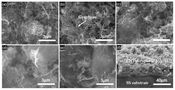
Typical SEM images of the pristine CNTs and CNT-Graphene hybrids are exhibited in Figure 2. As shown in Figure 2a, after deposition on the SS substrate, the pristine CNTs exhibited entanglements due to the existence of MgO after heat treatment [5,10]. As shown in Figure 2b, the surfaces of the CNTs were covered by a few graphene sheets. With increasing the concentration of the graphene (Figure 2c,d), the electrode surface was mixed with more graphene sheets. When the content of graphene was increased up to 0.4 g·L−1 (Figure 2e), the surface was almost completely wrapped by the graphene sheets, similar results could be observed in other hybrids, e.g., CoMoO4 modified with chitosan [21,22]. Figure 2f illustrates the cross-section of the CNT-Graphene hybrid, showing the tightly binding properties between the CNT-Graphene hybrid of about 30 μm thick and the SS substrate.
Figure 2.
SEM images of the pristine CNTs and CNT-Graphene hybrids. (a) the pristine CNTs, (b–e) the hybrids obtained by adding 0.04, 0.1, 0.2, and 0.4 g·L−1 graphenes in the suspension, respectively, (f) Cross-section of the CNT-Graphene hybrid. Note: The concentrations of CNTs and Mg2+ were kept certain values of 0.1 and 0.03 g·L−1, respectively [10].
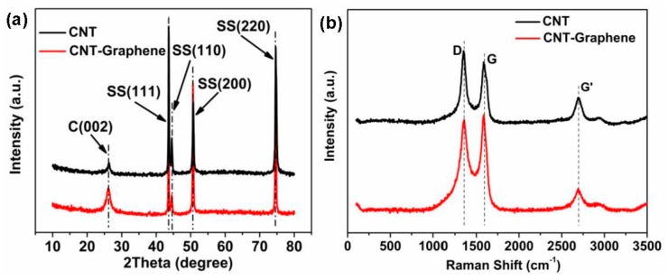
XRD and Raman characterizations were applied to check the compositions of the products, as shown in Figure 3. XRD result (Figure 3a) indicates that the peak at 26.4° belongs to (002) crystallographic planes of CNT [10,11,23], and other four peaks should be attributed to the (111), (110), (200), and (220) planes of the stainless steel substrate, respectively [10,11]. As shown in Figure 3b, the Raman spectrum shows three typical characteristic peaks of the CNTs, i.e., D band (1350 cm−1), G band (1585 cm−1), and G’ (2706 cm−1), respectively [11,24]. The D band represents the defects of CNTs due to the existence of the disordered carbon structures in CNTs. The G band represents the graphite degree of CNTs [11]. In comparison with the pristine CNT, higher G peak from the CNT-Graphene hybrid shows better graphitization due to the introduction of the graphene. Generally, the higher the IG/ID ratio, the better the conductivity of the sample [11,25,26]. Compared to the pristine CNTs, the higher IG/ID ratio of the CNT-Graphene-0.1 hybrid suggests that the construction of CNT-Graphene hybrid would enhance the electrode conductivity.
Figure 3.
(a) XRD and (b) Raman results of the pristine CNTs and CNT-Graphene-0.1 hybrid.
3.2. Tensile and the Surface Resistances Tests
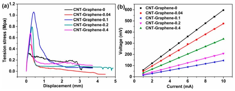
From Figure 4a, all the CNT-Graphene hybrids exhibited higher maximum stresses than the pristine CNTs, showing clearly the adhesion improvement with the addition of graphene. Meanwhile, the maximum stress, i.e., the adhesion, of the hybrid depended highly on the graphene concentration. As shown in Figure 4b, the four-probe test showed the surface resistance of the pristine CNT electrode of about 59.6 Ω. Compared with the pristine CNT electrode, the CNT-Graphene hybrid electrodes showed lower surface resistances of 47.5, 14.6, 20.9, and 33.9 Ω, respectively, corresponding to the graphene contents of 0.04, 0.1, 0.2, and 0.4 g·L−1, demonstrating significant reductions of surface resistances with graphene doping. The CNT-Graphene-0.1 hybrid electrode exhibited the lowest resistance, attributed mainly to two reasons. Firstly, comparing with other grapheme doped electrodes, the CNT-Graphene-0.1 electrode presented the highest adhesion value (Figure 4a), implying the best surface contact between the hybrid and the substrate. Secondly, excessive graphene doping may lead to the agglomeration of the graphene and over-enwrapping of the CNTs with graphene sheets (Figure 2d,e), weakening the intrinsic CNT property drastically.
Figure 4.
(a) Tensile curves and (b) surface resistance measurements of the pristine CNT and the CNT-Graphene hybrid electrodes.
3.3. TEC Measurements
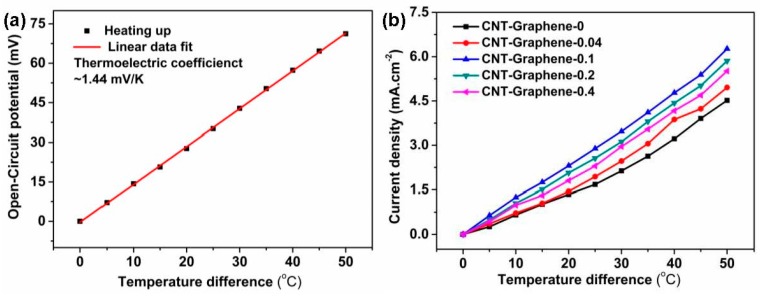
The Cup-Shaped device was used to investigate the TEC performances of the pristine CNT and CNT-Graphene hybrid electrodes [5,11]. As shown in Figure 5a, by linear fitting, the thermoelectric coefficient is about 1.44 mV·K−1, in agreement with the previous reports for potassium ferri/ferrocyanide electrolyte [4,5,11]. For the TEC electrodes, the current densities (JSC) increased with the temperature differences (Figure 5b). Compared with the pristine CNT electrode, the CNT-Graphene hybrid electrodes exhibited higher JSC at the same temperature difference, due to the better electrical and thermal conductivities [27,28,29] and stronger adhesion between the CNT-Graphene film and the substrate. Among all hybrid electrodes, the CNT-Graphene-0.1 exhibited the best TEC performance, with JSC of 62.8 A·m−² and JSC/ΔT of 1.25 A·m−2·K−1) under a temperature difference of 50 °C.
Figure 5.
(a) Cell potential versus temperature difference, and (b) current density versus temperature difference of the pristine CNT and CNT-Graphene hybrid electrodes, each electrode surface area is 0.36 cm2.
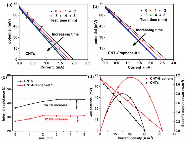
The discharge curves, the fitting relation between the internal resistance (R) with the test time, and the plots of the specific output power (P) of the TECs for the pristine CNT and CNT-Graphene-0.1 hybrid electrodes were shown in Figure 6. As shown in Figure 6a,b, the internal resistances climbed with increasing the test time for both pristine CNT and CNT-Graphene-0.1 hybrid electrodes. R could be obtained by linear fitting based on U-I curves, where U and I represented the cell potential and output current of the electrode, respectively. The output current of the electrode could be adjusted by changing the external resistance (Rext) according to the relation: U = Voc–IR, where Voc is the open-circuit potential, which is mainly determined by the temperature difference [6], and R relies on the structure of the TEC [6,14,30]. For the given temperature difference, Voc can be regarded as a constant, thus the relationship between U and I is approximately linear. During the continuous operation for the TEC, the built up concentration gradient, i.e., the mass transport overpotential, could be easily formed at the cold side [8,11]. The mass transport overpotential could be investigated by measuring the relation between the time and the internal resistance. As shown in Figure 6c, for the CNT-Graphene-0.1 hybrid electrode, TEC experienced a 2 min equilibrium process before obtaining a steady R, less time than the pristine CNT electrode of 3 min. In addition, the CNT-Graphene-0.1 hybrid electrode reached a steady state with R of 31.05 Ω, lower than that of the pristine CNT electrode of 42.63 Ω, attributed to the lower thermal resistance [20,27,28]. The output power is obtained based on the equation: P = UI = (Voc–IR) I = Voc I–I2R, thus a quadratic relationship can be observed in the P–I curve (Figure 6d). As shown in Figure 6d, the CNT-Graphene-0.1 hybrid electrode generated JSC of 62.8 A·m−2 and PMAX of 1.15 W·m−2 at the temperature different of 50 °C, corresponding to a normalized current density of 1.26 A·m−2·K−1 and specific power density of 0.460 mW·m−2·K−2, respectively, 30.4% higher than those for the pristine CNT electrode, due to better conductivity and lower thermal resistance at the electrode/substrate junction [4,5,20].
Figure 6.
(a) Cell potential versus current for (a) CNT and (b) CNT-Graphene-0.1 electrodes, (c) fitting curve of internal resistance versus test time, and (d) plots of cell potential and specific output power versus current density at the steady state.
The energy conversion efficiency (η) can be obtained using the following formula [4,8,12]:
Isc and Voc are the short-circuit current and the open-circuit potential, respectively. A is the area of the test electrode, k is the thermal conductivity of the potassium ferri/ferrocyanide, ∆T and d are the temperature difference and the distance of the test electrodes, respectively. The relative energy conversion efficiency (ηr) can be achieved by the equation: ηr = η/(∆T/Th) [4,5,11], where Th is the temperature of the hot side. Based on the above equations, ηr of the pristine CNT electrode and CNT-Graphene-0.1 hybrid electrode reached 0.95% and 1.35%, respectively, at the temperature difference of 50 °C. Comparing with the CNT and CNT-based hybrid electrodes, the TEC performance of CNT-graphene-0.1 was moderate (See Table S1 in Supplementary Materials). Future investigations should focus on the optimization of the carbon nanomaterial with lower thermal resistance and high conductivity, e.g., single wall CNTs or doped CNTs [7,31,32]. In addition, to obtain high ηr, it would be preferred to select the flowing type TEC to decrease further the solution diffusion resistance [4,33].
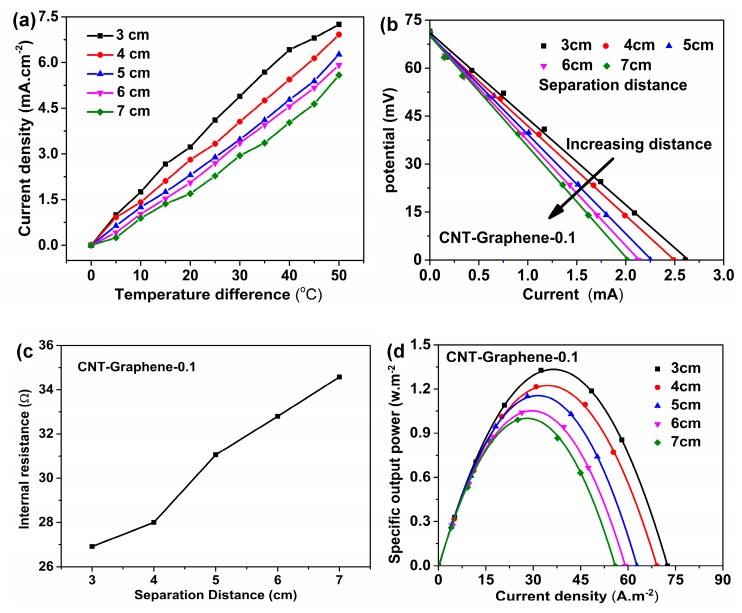
The temperature difference versus current density, the discharge curves, the fitting results of the internal resistance, and the plots of the specific output power of the TECs for the CNT-Graphene-0.1 hybrid electrode with different separation distances are shown in Figure 7. As shown in Figure 7a, with increasing the distance between the two CNT-Graphene-0.1 hybrid electrodes, the current density decreased correspondingly at the same temperature difference. In addition, the current density increased to 4.89 mA·cm−2 at a distance of 3 cm, 39.88% higher than that of 7 cm at the temperature different of 30 °C. Figure 7b shows different U-I curves corresponding with varying the distance, and each internal resistance can be obtained by linear fitting of the corresponding U-I curve. The values of R in Figure 7c are derived from the linear fitting of U-I curves in Figure 7b. As shown in Figure 7c, the internal resistance of the TEC increased from 26.91 Ω to 34.58 Ω, corresponding to the distance from 3 cm to 7 cm, due to extended diffusion distances of the solution [14]. As shown in Figure 7d, while reducing the separation distance of two electrodes from 7 cm to 3 cm, the specific output power could increase up to 1.33 w·m−2 at the distance of 3 cm, associated mainly to the drops of the internal resistance and the mass transport overpotentials [6,14]. However, the relative energy conversion efficiency decreased from 1.58 to 0.96, because the heat transport turns to be quicker thus more input thermal energy is needed to keep the same temperature difference with reducing the distance, leading to the decline of the relative energy conversion efficiency [14].
Figure 7.
(a) Temperature difference versus current density, (b) Cell potential versus current, (c) Internal resistance versus time, and (d) plots of specific output power versus current density at different separation distances for the CNT-Graphene-0.1 hybrid electrode.
4. Conclusions
In this paper, CNT-Graphene hybrids were synthesized on stainless steel substrates using the electrophoretic deposition (EPD) technique to make the TEC electrodes. Such hybrid electrodes show significantly improved TEC performances in comparison with the pristine CNT electrode, due to better electrical and thermal conductivities and stronger adhesion between the CNT-Graphene hybrid electrode and the substrate. By tuning the concentrations of the graphene in the suspension, the hybrid electrodes could be optimized with the maximum current density of 62.8 A·m−2 and the power density of 1.15 W·m−2 at a temperature different of 50 °C, 30.4% higher than the pristine CNT electrode. Meanwhile, the relative conversion efficiency of 1.35% could be reached. These results suggest that the production of CNT-Graphene hybrid electrodes by EPD technique may offer a promising approach for developing CNT-based TEC electrode materials.
Supplementary Materials
The following are available online at https://www.mdpi.com/2079-4991/9/10/1450/s1, Table S1: Comparison on TEC performances of different nanomaterials.
Author Contributions
Y.Z. and W.H. synthesized and characterized the samples. B.L. and H.L. analyzed the data. W.Q. and C.D. designed the experiments and wrote this paper.
Funding
The authors gratefully acknowledge the financial support by National Natural Science Foundation of China (Grant No. 61871292, 61620106006, 51302193).
Conflicts of Interest
The authors declare no conflict of interest.
References
- 1.Burmistrov I., Kovyneva N., Gorshkov N., Gorokhovsky A., Durakov A., Artyukhov D., Kiselev N. Development of new electrode materials for thermo-electrochemical cells for waste heat harvesting. Renew. Energ. Focus. 2019;29:42–48. doi: 10.1016/j.ref.2019.02.003. [DOI] [Google Scholar]
- 2.Alzahrani H.A.H., Black J.J., Goonetilleke D., Panchompoo J., Aldous L. Combining thermogalvanic corrosion and thermogalvanic redox couples for improved electrochemical waste heat harvesting. Electrochem. Commun. 2015;58:76–79. doi: 10.1016/j.elecom.2015.06.007. [DOI] [Google Scholar]
- 3.Kundu A., Fisher T.S. Harnessing the thermogalvanic effect of the ferro/ferricyanide redox couple in a thermally chargeable supercapacitor. Electrochim. Acta. 2018;281:357–369. doi: 10.1016/j.electacta.2018.05.164. [DOI] [Google Scholar]
- 4.Hu R.C., Cola B.A., Haram N., Barisci J.N., Lee S., Stoughton S., Wallace G., Too C., Thomas M., Gestos A., et al. Harvesting waste thermal energy using a carbon-nanotube-based thermo-electrochemical cell. Nano Lett. 2010;10:838–846. doi: 10.1021/nl903267n. [DOI] [PubMed] [Google Scholar]
- 5.Qian W.J., Cao M.X., Xie F., Dong C.K. Thermo-electrochemical cells based on carbon nanotube electrodes by electrophoretic deposition. Nano-Micro Lett. 2016;8:240–246. doi: 10.1007/s40820-016-0082-8. [DOI] [PMC free article] [PubMed] [Google Scholar]
- 6.Gunawan A., Lin C.H., Buttry D.A., Mujica V., Taylor R.A., Prasher R.S., Phelan P.E. Liquid thermoelectrics: Review of recent and limited new data of thermogalvanic cell experiments. Nanoscale Microscale Thermophys. Eng. 2013;17:304–323. doi: 10.1080/15567265.2013.776149. [DOI] [Google Scholar]
- 7.Salazar P.F., Kumar S., Cola B.A. Nitrogen- and boron-doped carbon nanotube electrodes in a thermo-electrochemical cell. J. Electrochem. Soc. 2012;159:B483–B488. doi: 10.1149/2.043205jes. [DOI] [Google Scholar]
- 8.Im H., Moon H.G., Lee J.S., Chung I.Y., Kang T.J., Kim Y.H. Flexible thermocells for utilization of body heat. Nano Res. 2014;7:443–452. doi: 10.1007/s12274-014-0410-6. [DOI] [Google Scholar]
- 9.Yang H.D., Tufa L.T., Bae K.M., Kang T.J. A tubing shaped, flexible thermal energy harvester based on a carbon nanotube sheet electrode. Carbon. 2015;86:118–123. doi: 10.1016/j.carbon.2015.01.037. [DOI] [Google Scholar]
- 10.Qian W.J., Li M.J., Chen L.H., Zhang J.H., Dong C.K. Improving thermo-electrochemical cell performance by constructing Ag–MgO–CNTs nanocomposite electrodes. RSC Adv. 2015;5:97982–97987. doi: 10.1039/C5RA19182C. [DOI] [Google Scholar]
- 11.Zhao F., Qian W.J., Li M.J., Li W., Chen L.H., Zhong F.Y., Huang W.J., Dong C.K. Directly grown carbon nanotube based hybrid electrodes with enhanced thermo-cell performances. RSC Adv. 2017;7:23890–23895. doi: 10.1039/C7RA02264F. [DOI] [Google Scholar]
- 12.Im H., Kim T., Song H., Choi J., Park J.S., Ovalle-Robles R., Yang H.D., Kihm K.D., Baughman R.H., Lee H.H., et al. High-efficiency electrochemical thermal energy harvester using carbon nanotube aerogel sheet electrodes. Nat. Commun. 2016;7:10600. doi: 10.1038/ncomms10600. [DOI] [PMC free article] [PubMed] [Google Scholar]
- 13.Romano M.S., Li N., Antiohos D., Razal J.M., Nattestad A., Beirne S., Fang S.L., Chen Y.S., Jalili R., Wallace G.G., et al. Carbon nanotube–reduced graphene oxide composites for thermal energy harvesting applications. Adv. Mater. 2013;25:6602–6606. doi: 10.1002/adma.201303295. [DOI] [PubMed] [Google Scholar]
- 14.Kang T.J., Fang S.L., Kozlov M.E., Haines C.S., Li N., Kim Y.H., Chen Y.S., Baughman R.H. Electrical power from nanotube and graphene electrochemical thermal energy harvesters. Adv. Funct. Mater. 2012;22:477–489. doi: 10.1002/adfm.201101639. [DOI] [Google Scholar]
- 15.Boccaccini A.R., Cho J., Roether J.A., Thomas B.J.C., Minay E.J., Shaffer M.S.P. Electrophoretic deposition of carbon nanotubes. Carbon. 2006;44:3149–3160. doi: 10.1016/j.carbon.2006.06.021. [DOI] [Google Scholar]
- 16.Geng X.M., Zhang Y.L., Jiao L., Yang L., Hamel J., Giummarella N., Henriksson G., Zhang L.M., Zhu H.L. Bioinspired ultrastable lignin cathode via graphene reconfiguration for energy storage. ACS Sustain. Chem. Eng. 2017;5:3553–3561. doi: 10.1021/acssuschemeng.7b00322. [DOI] [Google Scholar]
- 17.Raccichini R., Varzi A., Passerini S., Scrosati B. The role of graphene for electrochemical energy storage. Nat. Mater. 2015;14:271–279. doi: 10.1038/nmat4170. [DOI] [PubMed] [Google Scholar]
- 18.Georgakilas V., Tiwari J.N., Kemp K.C., Perman J.A., Bourlinos A.B., Kim K.S., Zboril R. Noncovalent functionalization of graphene and graphene oxide for energy materials, biosensing, catalytic, and biomedical applications. Chem. Rev. 2016;116:5464–5519. doi: 10.1021/acs.chemrev.5b00620. [DOI] [PubMed] [Google Scholar]
- 19.Chiu H.Y., Cho C.P. Mixed-phase MnO2/N-containing graphene composites applied as electrode active materials for flexible asymmetric solid-state supercapacitors. Nanomaterials. 2018;8:924. doi: 10.3390/nano8110924. [DOI] [PMC free article] [PubMed] [Google Scholar]
- 20.Wang J.G., Mu X.J., Sun M.T. The Thermal, Electrical and Thermoelectric Properties of Graphene Nanomaterials. Nanomaterials. 2019;9:218. doi: 10.3390/nano9020218. [DOI] [PMC free article] [PubMed] [Google Scholar]
- 21.Ramkumar R., Minakshi M. Fabrication of ultrathin CoMoO4 nanosheets modified with chitosan and their improved performance in energy storage device. Dalton Trans. 2015;44:6158–6168. doi: 10.1039/C5DT00622H. [DOI] [PubMed] [Google Scholar]
- 22.Ramkumar R., Sundaram M.M. A biopolymer gel-decorated cobalt molybdate nanowafer: Effective graft polymer cross-linked with an organic acid for better energy storage. New J. Chem. 2016;40:2863–2877. doi: 10.1039/C5NJ02799C. [DOI] [Google Scholar]
- 23.Ibrahim R., Hussein M.Z., Yusof N.A., Bakar F.A. Carbon nanotube-quicklime nanocomposites prepared using a nickel catalyst supported on calcium oxide derived from carbonate stones. Nanomaterials. 2019;9:1239. doi: 10.3390/nano9091239. [DOI] [PMC free article] [PubMed] [Google Scholar]
- 24.Kholmanov I., Kim J., Ou E., Ruoff R.S., Shi L. Continuous carbon nanotube–ultrathin graphite hybrid foams for increased thermal conductivity and suppressed subcooling in composite phase change materials. ACS Nano. 2015;9:11699–11707. doi: 10.1021/acsnano.5b02917. [DOI] [PubMed] [Google Scholar]
- 25.Fagan S.B., Filho A.G.S., Lima J.O.G., Filho J.M., Ferreira O.P., Mazali I.O., Alves O.L., Dresselhaus M.S. 1,2-Dichlorobenzene interacting with carbon nanotubes. Nano Lett. 2004;4:1285–1288. doi: 10.1021/nl0493895. [DOI] [Google Scholar]
- 26.Dresselhaus M.S., Dresselhaus G., Jorio A., Filho A.G.S., Saito R. Raman spectroscopy on isolated single wall carbon nanotubes. Carbon. 2002;40:2043–2061. doi: 10.1016/S0008-6223(02)00066-0. [DOI] [Google Scholar]
- 27.Cheng H.H., Dong Z.L., Hu C.G., Zhao Y., Hu Y., Qu L.T., Chen N., Dai L.M. Textile electrodes woven by carbon nanotube–graphene hybrid fibers for flexible electrochemical capacitors. Nanoscale. 2013;5:3428–3434. doi: 10.1039/c3nr00320e. [DOI] [PubMed] [Google Scholar]
- 28.Zhu Y., Li L., Zhang C.G., Casillas G., Sun Z., Yan Z., Ruan G., Peng Z., Raji A.-R.O., Kittrell C., et al. A seamless three-dimensional carbon nanotube graphene hybrid material. Nat. Commun. 2012;3:1225. doi: 10.1038/ncomms2234. [DOI] [PubMed] [Google Scholar]
- 29.Im H., Kim J. Thermal conductivity of a graphene oxide–carbon nanotube hybrid/epoxy composite. Carbon. 2012;50:5429–5440. doi: 10.1016/j.carbon.2012.07.029. [DOI] [Google Scholar]
- 30.Quickenden T.I., Mua Y. A review of power generation in aqueous thermogalvanic cells. J. Electrochem. Soc. 1995;142:3985–3994. doi: 10.1149/1.2048446. [DOI] [Google Scholar]
- 31.Pop E., Mann D., Wang Q., Goodson K., Dai H. Thermal conductance of an individual single-wall carbon nanotube above room temperature. Nano Lett. 2006;6:96–100. doi: 10.1021/nl052145f. [DOI] [PubMed] [Google Scholar]
- 32.Berber S., Kwon Y.-K., Tomanek D. Unusually high thermal conductivity of carbon nanotubes. Phys. Rev. Lett. 2000;84:4613–4616. doi: 10.1103/PhysRevLett.84.4613. [DOI] [PubMed] [Google Scholar]
- 33.Kim T., Lee J.S., Lee G., Yoon H., Yoon J., Kang T.J., Kim Y.H. High thermopower of ferri/ferrocyanide redox couple in organic-water solutions. Nano Energy. 2017;31:160–167. doi: 10.1016/j.nanoen.2016.11.014. [DOI] [Google Scholar]
Associated Data
This section collects any data citations, data availability statements, or supplementary materials included in this article.


