

Abstract
A simple passive microfluidic device that continuously separates microparticles is presented. Its development is motivated by the need for specific size micro perfluorocarbon (PFC) droplets to be used for a novel gas embolotherapy method. The device consists of a rectangular channel in which inertial lift forces are utilized to separate particles in lateral distance. At the entrance of the channel, particles are introduced at the center by focusing the flow from a center channel with flow from two side channels. Downstream, large particles will occupy a lateral equilibrium position in shorter axial distance than small particles. At the exit of the channel, flow containing large particles is separated from flow containing small particles. It is shown that 10.2 μm diameter microspheres can be separated from 3.0 μm diameter microspheres with a separation efficiency of 69-78% and a throughput in the order of 2 · 104 particles per minute. Computational Fluid Dynamics (CFD) calculations were done to calculate flow fields and verify theoretical particle trajectories. Theory underlying this research shows that higher separation efficiencies for very specific diameter cut-off are possible. This microfluidic channel design has a simple structure and can operate without external forces which makes it feasible for lab-on-a-chip (LOC) applications.
1. Introduction
In this study, a microchannel device is designed and fabricated that can passively separate perfluorocarbon (PFC) microdroplets in diameter and could be integrated on a lab-on-a-chip (LOC) device. The study is motivated by the need for ~6 micrometer diameter PFC droplets that are to be used for a novel type of gas embolotherapy method [1, 2, 3] which is more precise and less invasive than other methods. In this method the aim is to locally occlude the blood flow in the vasculature upstream of tumor cells with gas emboli [4]. Gas emboli are formed in vivo in feeder vessels leading to tumor cells by acoustic droplet vaporization (ADV) of superheated, but stable, PFC droplets which have been injected intravenously [5, 6]. It is of importance that the PFC droplets have a diameter not larger than 6 micrometers to prevent droplet lodging in the capillary bed [7]. It is desired that the droplets are not too small as they would after ADV form a gas bubble that would not lodge but still contribute to the total amount of PFC in the blood. If that amount is too large, it could lead to pulmonary dysfunction [8, 9].
High accuracy sorting of microparticles such as cells, spheres and droplets in diameter is already required in a number of (prospective) medical, industrial and environmental applications [10, 11, 12]. The traditional macroscale method of membrane filtering is not suitable for microparticles due to high costs, sensitivity to clogging, and incapability to separate a range of particles of different sizes [13]. The need for devices which can filter or separate microparticles has led to the development of different separation techniques such as centrifugation, field-flow fractionation (FFF) [14], split-flow thin (SPLITT) fractionation [15], capillary electrophoresis and chromotography. However, each of these techniques have their disadvantages such as the need for additional (mechanical) parts, batch-mode operation or small throughput which would make them undesirable or unsuitable to be used as a LOC device for applications like the one that motivates this study [13]. To avoid these disadvantages, recent research has focused on designing microchannel geometries to passively and continuously focus, separate or sort microparticles using inertial forces in hydrodynamic flow [16, 13, 17, 11, 18, 19, 20, 21].
In this study, the laterally directed inertial lift force that acts on particles immersed in Poiseuille flow through a straight channel is used for particle separation. This lift force causes particles to occupy certain lateral equilibrium positions in the channel. The equilibrium positions are independent of particle radius, however the magnitude of the inertial lift force is strongly dependent on particle radius (~ a4 where a is the particle radius). Therefore this phenomenon of lateral migration of particles in straight channels has the potential for high accuracy sorting based on particle diameter. In contrast to previous studies concerning microparticle separation using solely the lateral lift force [22], this research introduces the concept of focusing the particles towards the lateral center of the microchannel at the entrance with confluent flow (flow from a center channel containing the particles is focused by two side channels). The significant advantage of this particular method is that it allows in theory for full particle separation. This study consisted of designing and fabricating a microchannel and performing measurements on it using fluorescent microspheres as a model for PFC droplets. Flow fields at the entrance and exit of the channel were studied with Computational Fluid Dynamics (CFD).
2. Methods
2.1. Theory
A study by Ho and Leal [23] provided a full description of the lateral force Fl on a neutrally buoyant sphere (radius a) as a function of lateral position in two-dimensional Poiseuille flow, see Figure 1, for small Reynolds numbers Re ≪ 1. Channel width is defined as L, center velocity of the Poiseuille flow as Um, dynamic viscosity of the fluid as μ and density of the fluid as ρ. Axial distance is defined as x and normalized lateral distance as s where s = y/L. The solution was found by obtaining the velocity and pressure fields from solving the Stokes flow equations with regular perturbation methods. The study provided conditions for the maximum concentration of spheres for the theory (which is based on a single sphere) to hold. If δ is the number of spheres per unit volume, then δ must satisfy δ2 ≪ (9/16)π−2a−3L−3. A study by Schonberg and Hinch [24] extended the restriction of small Re by employing a singular perturbation expansion which provided a result that is valid for Re up to 100. The result of these theoretical studies is an expression for the lateral force Fl as a function of the normalized lateral distance s:
| (1) |
where f(s), plotted in Figure 2, is a tabulated function which depends on the model that is used. The Schonberg and Hinch model will be used for this study. The lift force on a sphere leads to a lateral lift velocity of the sphere Ul which is related to the force through Stokes drag. The lateral lift velocity Ul can also be given as a function of s:
| (2) |
Figure 1:
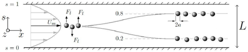
Coordinate system, flow profile and migration of spheres to lateral equilibrium positions.
Figure 2:
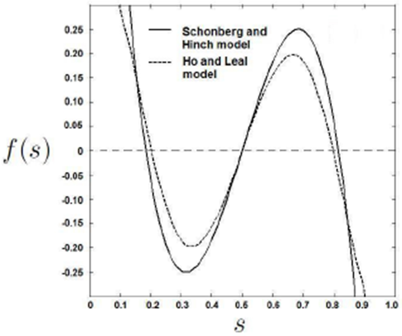
Tabulated function f(s) for equation 2. Equilibrium positions can be observed for s where f(s) = 0.
Sphere trajectories (normalized lateral position s vs. axial distance x) can be obtained by integration as demonstrated in [23]. Axial slip velocity, which is the axial velocity difference between the sphere and the surrounding fluid, can for this study be neglected. The trajectories for spheres of different radii released at 0.49s have been plotted in Figure 3 which shows the strong relation between the distance a particle needs to equilibrate and its radius.
Figure 3:
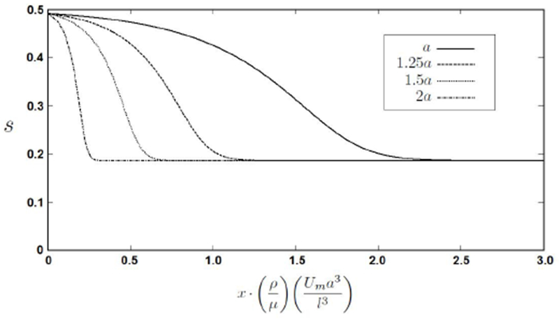
Sphere trajectories for spheres of four different radii all released at 0.49s, normalized lateral positions vs. normalized axial position. This graph shows the strong relation between sphere radius and the axial distance it needs to equilibrate.
In three dimensional rectangular channels (width L and height H in the z-direction), spheres also migrate to equilibrium positions depending on the channel aspect ratio (AR = H/L) of the channel and depending on channel Reynolds number. The channel Reynolds number, Rc, is defined as:
| (3) |
Where Hd = (2HL)/(H+L) is the hydraulic diameter of the channel, and is the average velocity in the channel (which is the flow rate divided by cross section HL). Flow rate can be linked to Um by integrating the velocity profile in a three dimensional rectangular channel which is given by [25]:
| (4) |
Equilibrium positions for spheres in a square and a rectangular channel have been studied by Bhagat [16, 22]. It has been shown that already for a rectangular channel with AR = 2 spheres will equilibrate completely along the long, vertical, walls for 20 < Rc < 100. In the case of (near) square shaped channels, spheres will also equilibrate in a center position along the short, horizontal, walls. For very high aspect ratios (AR ≫ 1), the two-dimensional situation will be approached and spheres will equilibrate along the long walls [26].
2.2. Experiments
Theory shows that only microchannels with a maximum width of ~ 100 μm can produce enough lift force on ~ 6 μm diameter spheres to let them reach the equilibrium positions within an axial distance of 5 cm with channel flow rates that would not result in pressure drops over the device of over ~ 1 bar. The limitation of the channel length to 5 cm is to make the device feasible for LOC applications. The channel is made out of polydimethylsiloxane (PDMS) which is transparent, so optical measurements to study particle behavior within the channel can be performed. The limitation of a pressure drop not larger than ~ 1 bar is determined because leakage was observed at tubing connections at inlets and outlets at that pressure. To study particle behavior in the microchannel, fluorescent microspheres are used with the assumption that PFC droplets can be modeled with microspheres. The microspheres are believed to be a sufficient model for the PFC droplets for two reasons. The first is that if Rc ≈ 100, the Weber number, We = ρdUm22a/σ = 0.5 for albumin coated PFC droplets which have a surface tension in water of σ = 7 · 10−2 N/m [27] and a density of ρd = 1.6 · 103 kg/m3. Since We is smaller than 1, it indicates that surface tension forces are larger than inertial forces and thus keep the droplet spherical. The second reason is that a PFC droplet is expected to behave reasonably similar to a solid sphere under the influence of a lift force. The lift velocity and lift force (equations 1 and 2) are linearly related by Stokes drag: F = 6πμaU [28]. Batchelor [29] generalized this equation to include the case of a liquid sphere with a viscosity μl: Fl = 4πμaU(μ + 1.5μl)/(μ + μl). For the same lift force, a liquid PFC droplet (μl = 6.4 · 10−4 kgm−1s−1) will have a slightly larger (20%) lift velocity than a solid sphere of the same diameter.
The design of the microchannel is illustrated in Figure 4. It consists of 3 inlets to a main channel which is split up at the end in 3 outlets. The entrance center inlet, containing the particles, is focused by flows of carrier liquid originating from the entrance sides inlet. This way, all particles enter the main channel at or near the lateral center. The flow then develops into a Poiseuille profile in relatively short axial distance, which can be estimated with Ls ≈ Hd(0.61.6 + (0.04Rc)1.6)1/1.6, where Ls is the developing distance [30]. In the main channel, the lift force pushes the particles away from the center towards the sides of the channel. The theory indicates that flow rates on the order of ~60 ml/h (Rc ≈ 100) are sufficient to just laterally equilibrate ~6 μm diameter spheres at the end of the main channel, while smaller spheres will still be near the lateral center. At the exit of the main channel, the part of the flow near the walls (containing solely large particles) is split off from the center flow (containing smaller particles). The angle between the side channels and the main channel is not made smaller than ~ 30° since limitations in PDMS fabrication will else result in significant softening of the corners. The entrance center channel, as well as the exit center and exit sides channels are designed to have a minimum width of 30 μm to prevent blockage of large PFC droplets for the future application of this microfluidic device. Due to high flow velocity in the channel, lateral Brownian motion of particles can be neglected, as well as sedimentation effects.
Figure 4:
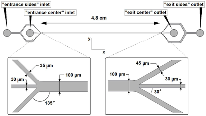
Top view of the microchannel. Names of inlets and outlets are indicated and the dimensions of the channel are given. Entrance and exit are enlarged.
The microchannel was fabricated using basic soft lithography techniques. The mold was made on a 10 cm diameter silicon wafer (University Wafer, South Boston, MA). SU-8 2150 photoresist (MicroChem Corp., Newton, MA) was spincoated on the wafer, baked, and exposed to UV light as prescribed by the Microchem processing guidelines for SU-8 2000. The mask used during the UV light exposure step was a negative print of the CAD drawing (Solidworks 2009) of the channel. The uniform height H of the microchannel was determined by the thickness of the SU-8 layer which was measured with a surface profiler (Alpha Step 500) after completion of the mold. It was measured to be 230 μm, which is sufficiently large to garentuee that all particles will equilibrate long the long walls only. To fabricate the channel, PDMS prepolymer Sylgard 184 Silicone elastomer base was mixed with Sylgard 184 Silicone curing agent (both from Dow Corning Corp., Midland, MI) in a 10:1 ratio, degassed, and cast over the mold and cured at room temperature for 48 hours. The PDMS was then peeled off the mold and bonded to a flat surface of clean PDMS with plasma oxidation (RIE-2000 South Bay Technology Inc.) to complete the channel. Tygon tubing was connected from the microchannel entrance locations to syringe pumps (Harvard Apparatus PHD 2000 and kd Scientific) and from the microchannel exit locations to separate reservoirs.
A z-plane inside the transparent PDMS microchannel was visualized using optical microscopy. A Nikon Eclipse TE2000-S inverted microscope was used with a CFI Plan Fluor 10x magnification (numerical aperture of 0.3) objective. The depth of field is in the range of 8-14 μm (provided by Nikon). Dye (McCormick, Sparks, MD) with a diffusion constant of 1 · 10−9 m2s−1 [31] was used to visualize flows at the entrance. Fluorescent polystyrene microspheres (Sperotech Inc., Lake Forest, IL) with a density of 1050 kg/m3 were used to visualize pathlines of the microspheres within microchannels with epifluorescence microscopy. Two sizes of microspheres were used in this study. Water containing 7.6 · 104 spheres per ml with a diameter of 3.0 μm and 1.7 · 104 spheres per ml with a diameter of 10.2 μm was pumped through the entrance center channel. The combined concentration does not exceed the criterion for the theory to be valid. Water was pumped through the entrance sides inlet. A 12 bit CCD camera (Roper Scientific) was mounted on the microscope to digitally record the microscope image (with Streampix software). The microscope was focused in such a way that microsphere pathlines were visible as sharply as possible (z coordinate of the plane unknown). To create a composite image, an intensity difference frame was made by subtracting 2 consecutive frames. Then, 700 of those intensity difference frames were overlaid to form the composite image. To analyze lateral sphere distribution in channels, grayscale line scans across microchannel width were taken at the center of the composite images. Each individual grayscale line graph was normalized. A Multisizer 3 Coulter counter (Beckman Coulter, Brea, CA) was used to count the microspheres in a sample collected from the flow exiting a microchannel. It was calibrated using 6 μm diameter microspheres before being used.
2.3. Computational Fluid Dynamics
Steady-state two-dimensional flow fields at the entrance and exit where computed using COMSOL Multiphysics, where the two-dimensional CAD drawing of the microchannel was directly imported from Solidworks (sharp corners were made blunt to match the actual channel after it was fabricated in PDMS). Geometries were automatically meshed. Flow fields were solved with Direct Numerical Simulations (DNS) of the incompressible Navier Stokes equations using the UMFPACK solver. The mesh was refined until the flow field solution was independent of the mesh. Inflow boundary conditions (BC’s) were set to uniform normal velocity (with enough distance to let flow develop into Poiseuille flow), wall BC’s were defined as no slip, and outflow BC’s were set to zero pressure. The fluid was water at room temperature.
3. Results and Discussion
An optimum combination of the entrance center and entrance sides flow rates was determined by creating fluorescent microscopy composite images of the exit of the channel and observing the nature and intensity of the pathlines of the 10.2 μm diameter spheres. The 3.0 μm diameter microspheres could not be observed with fluoresent microscopy due to a too low fluorescent intensity of those spheres for concentrations not exceeding the criterion combined with the high flow rates. The main channel flow rate was always sufficiently large that theory predicts full equilibration of the 10.2 μm diameter spheres at the end of the channel. It was observed that increasing the overall flow rate in the main channel resulted in a lower fraction of 10.2 μm diameter microspheres exiting through the exit sides channels. This is in conflict with the theoretical model, since a higher Um should garentuee lateral equilibration of spheres in shorter axial distance. Furthermore, increasing the entrance sides flowrate with respect to the center flow rate (more lateral focusing) appeared to also decrease the fraction of large spheres exiting through the exit sides channels. These effects could be explained by flow field interference at the exit or by significant deviation of the actual flow profile from the ideal Poiseuille flow profile throughout the main channel. Eventually, an optimum flow rate combination was found: a flow rate of 15.0 ml/h for the entrance center inlet and a flow rate of 10.0 ml/h for the entrance sides (Rc = 42). This setting was used for the remainder of this experimental study and for the CFD study.
At five different axial locations, a composite image was created to show the lateral distribution of the 10.2 μm diameter microspheres. The composite images, as well as their grayscale line scans, are shown in Figure 5. They show that the full channel length is needed to laterally equilibrate all the spheres, which is in agreement with the (two-dimensional) theory. On the composite image of the entrance (Figure 5A) it can be seen that the spheres enter the main channel at a significant lateral distance from the lateral center and they also appear to be equilibrated in the center entrance channel before reaching the main channel. This significant lateral distance at the entrance is an undesired effect, since it will lead to a lower fraction of small spheres exiting through the exit center channel. It can on the other hand be seen as an desired effect, since the spheres will start out at a lateral distance where the lift force is large, and thus need less axial distance to equilibrate. It is seen that the spheres migrate to the channel sides (Figures 5A to D) and eventually a significant fraction of the spheres is seen to exit the channel through the sides (Figure 5E). The composite images should be looked at critically for a number of reasons. The first is that they are merely a two dimensional projection of a three dimensional situation, thus any information about lateral distribution in the z-plane is lost. The second is that a significant part of the spheres could be out of focus in the image, since the depth of field is relatively small compared to channel height. The third is that spheres at the lateral center have a larger axial velocity, and thus maybe cause less intensity on the composite images. To exactly determine the seperation effeciency, the collected volumes from the exit center outlet and exit sides outlet were analyzed with a Coulter counter. A graph of the normalized total counts is shown in Figure 6. It proves that the device in this study works and that there is significant separation. The seperation efficiency is lower than expected. For instance, similar microfluidic particle sorting devices have achieved seperation efficiencies of 90% [20]. A possible explanation for the lower seperation efficiency is the loss of small spheres through the sides which could be contributed to the fact that the spheres do not enter the main channel at the lateral center (and the lift force will only push all spheres further away from the center). The losses of small spheres through the exit sides or of large spheres through the exit center could also be due to deviation of the flow field in the main channel from the ideal Poiseuille flow. A microPIV study could reveal the actual flow fields in the channel, at the entrance and exit but also in the main channel to see how much the actual flow field deviates the theoretical Poiseuille flow profile. Furthermore, restrictions on channel design (the minimum width of 30 μm for the entrance center channel and the 100 μm width for the main channel) prevented the design of a channel which could have led to better focusing of the spheres, and obtaining a higher separation efficiency. Narrowing the main channel at the entrance, and widening it at the exit causing respectively converging and diverging flow could increase the focusing and separation of spheres and thus could increase the separation efficiency.
Figure 5:
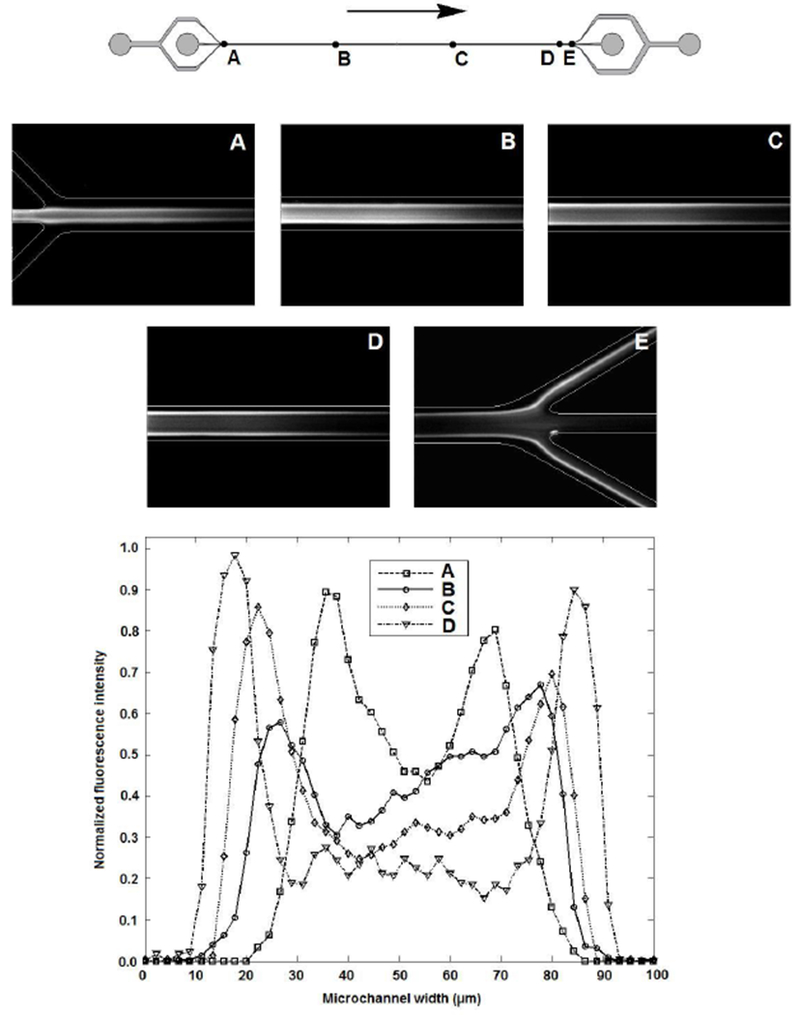
Composite images show lateral distribution of 10.2 μm diameter microspheres at five different axial locations as indicated in the drawing of the channel. Grayscale line scans (normalized) of composite images A through D are shown in the graph. Rc = 42.
Figure 6:
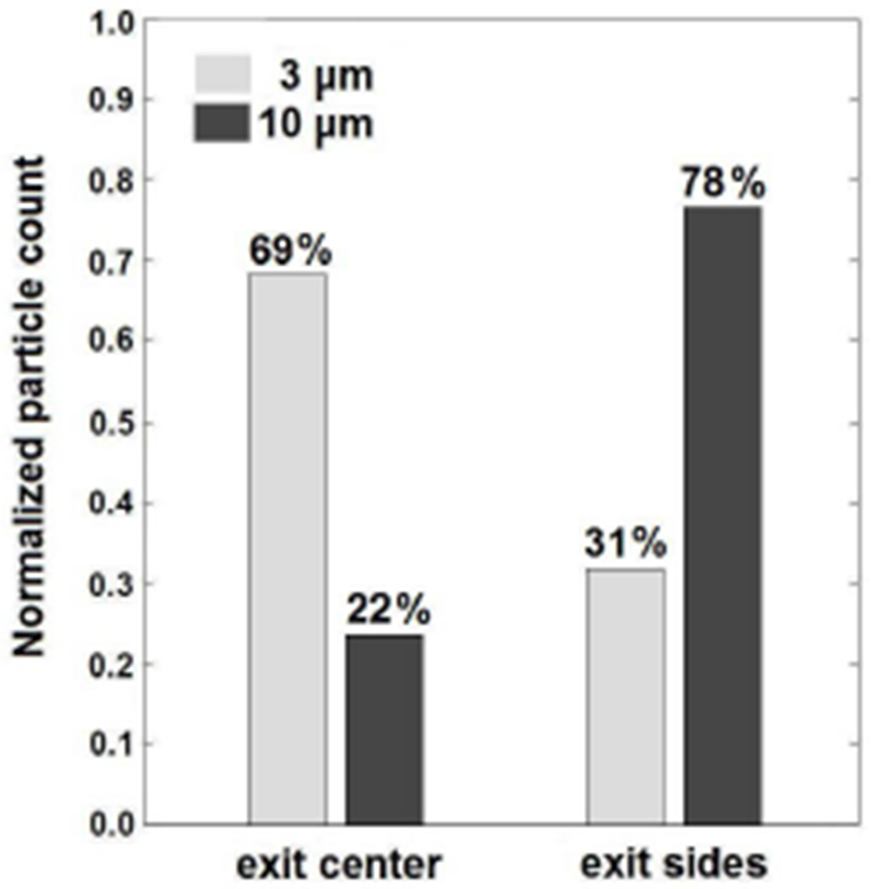
Coulter counter results which show separation of 10.2 μm diameter microspheres from 3.0 μm diameter microspheres.
To gain more understanding of the flow behavior and sphere trajectories at the entrance and exit, CFD was used to calculate the two-dimensional flow field (chosen to model the flow field in the z = 115 μm plane) at those locations. Instead of calculating the flow field in the entire channel, only the entrance and exit locations were taken and the main channel and side channels leading to or away from them were cut off sufficiently far upstream or downstream. For a flow rate in the main channel of the three-dimensional channel of 25.0 ml/h, the two-dimensional flow rate in the z = 115 plane was calculated to be 0.40 cm2/s (Um = 0.59 m/s) using equation 4. The calculated flow fields, and streamlines, are shown in Figure 7. Streamlines of interest, labeled by letter, are highlighted. Streamlines A and B originate from near the wall of the center entrance channel to illustrate focusing of the fluid originating from this center channel. Streamlines D and E illustrate that fluid originating from a lateral distance of s > 0.13 from the lateral center of the main channel will enter the exit side channels. Streamlines C and F are the streamlines that originate from a lateral distance of s = 0.31 from the lateral center of the main channel, which is the equilibration position. It can be assumed that the microspheres follow the streamlines for short axial distances where cross-streamline migration due to lift force can be neglected [16, 10]. With this assumption, streamlines C, F, D and E show that spheres which are at a lateral distance s > 0.13 from the lateral center of the main channel at the end of the main channel (this includes fully equilibrated spheres) will flow into the side exit channels. Despite the fact that the CFD calculations are two-dimensional and therefore do not predict the flow field in the real three-dimensional channel, they proved to be useful in providing insight into flow velocity profiles and confirming sphere trajectories (in at least the z = 115 μm plane). However, a three-dimensional CFD study should be conducted to study the trajectories of spheres that are not in the center plance in the z-direction. The CFD results here indicate that, in ideal flow conditions, equilibrated spheres exit the channel through the exit sides channels under the assumption that microspheres follow the streamlines. The pathlines of the spheres predicted with CFD are in good agreement with the experimental results (Figures 5A and E). CFD could be a first step towards optimizing the design of the channel: widening the exit and/or narrowing the entrance, could give a higher seperation efficiency. Flow fields at those locations could first be studied with CFD, before fabricating the channel.
Figure 7:
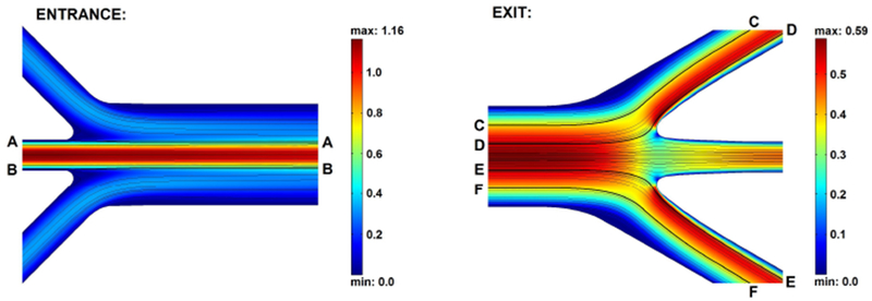
Two-dimensional CFD calculations of flow fields at entrance and exit with streamlines. Absolute velocities are plotted in (m/s). Streamlines of interest are highlighted and labelled A through F.
4. Conclusions
It has been demonstrated that it is possible to separate microparticles by utilizing solely the lateral lift force with the passive LOC device that was developed in this study. The theory that this device is based upon, indicates that a very high separation efficiency is possible, since lateral lift force strongly depends on particle radius (~ a4). This makes this concept worthy of further research. A great advantage of this concept of microparticle separation is that exact particle trajectories in the device can be calculated. While this is not the case for other recent microfluidic separation devices [17, 19, 20]. The separation efficiency of this device is lower than expected, but it could be increased by making geometrical changes. The throughput of this channel, 2.3 · 104 spheres per minute for the microsphere mixture, is in the same order of magnitude as other similar separation devices, however it is low (more than a factor of 10) compared to recent separation channel designs [20]. Positioning a number of straight channels in parallel or increasing the channel height would increase throughput. The specific application that motivated this research was the need to separate PFC droplets that are to be used for a novel gas embolotherapy method. No PFC droplets were separated in this research because this was beyond the scope of this study. Although it has been theoretically shown that PFC droplets are expected to behave similary to microspheres in this device, sedimentation might not be negligible, as well as inertia effects. To obtain PFC microdroplets of one specific diameter, this device could in a first run be used to eliminate large droplets from a mixture and then in a second run to eliminate the small droplets.
Acknowledgements
This work was supported by NIH grant RO1 EB006476.
References
- [1].Bull J. Bubble transport and sticking in gas embolotherapy. American Physical Society, Division of Fluid Dynamics:2002, 55th Annual Meeting. [Google Scholar]
- [2].Bull J, Calderon AJ et al. Transport of cardiovascular microbubbles in gas embolotherapy. American Physical Society, Division of Fluid Dynamics:2006, 59th Annual Meeting. [Google Scholar]
- [3].Bull J. Cardiovascular bubble dynamics. Critical Reviews in Biomedical Engineering, 33(4):299346, 2005. [DOI] [PubMed] [Google Scholar]
- [4].Calderon AJ, Heo YS, Fowlkes JB, Bull J et al. Microfluidic model of bubble lodging in microvessel bifurcations. Applied Physics letters, 89:244103, 2006. [Google Scholar]
- [5].Kripgans OD, Fowlkes JB et al. Acoustic droplet vaporization for therapeutic and diagnostic applications. Ultrasound in Med. Biol, 7:11771189, 2000. [DOI] [PubMed] [Google Scholar]
- [6].Kripgans OD, Fowlkes JB et al. In vivo droplet vaporization using diagnostic ultrasound - a potential method for occlusion therapy? Proceedings of the 2000 IEEE International Ultrasonics Symposium, PM-5:October 22–25, 2000, San Juan, PR. [Google Scholar]
- [7].Ye T and Bull J. Microbubble expansion in a flexible tube. Journal of Biomedical Engineering, 128:554–563, 2006. [DOI] [PubMed] [Google Scholar]
- [8].Leakakos T, Schutt EG, Cavin JC et al. Pulmonary gas trapping differences among animal species in response to intravenous infusion of perfluorocarbon emulsions. Artificial Cells, Blood Substitutes and Biotechnology, 22(4):1199–204, 1994. [DOI] [PubMed] [Google Scholar]
- [9].Eckmann DM, Swartz Me. A., Matthew et al. Perfluorocarbon induced alterations in pulmonary mechanics. Artificial Cells, Blood Substitutes and Biotechnology, 26(3):259–271, 1998. [DOI] [PubMed] [Google Scholar]
- [10].Huh D, Bahng JH, Ling Y et al. A gravity-driven microfluidic particle sorting device with hydrodynamic separation amplification. Anal. Chem, 74(4):13691376, 2007. [DOI] [PMC free article] [PubMed] [Google Scholar]
- [11].Di Carlo D, Edd JF, Irimia D et al. Equilibrium separation and filtration of particles using differential inertial focusing. Anal. Chem, 80:2204–2211, 2008. [DOI] [PubMed] [Google Scholar]
- [12].Sollier E, Rostainga H, Pouteaua P et al. Passive microfluidic devices for plasma extraction from whole human blood. Sensors and Actuators B, 141:617–624, 2009. [Google Scholar]
- [13].Bhagat AAS, Kuntaegowdanahalli SS, Papautsky I. Continuous particle separation in spiral microchannels using dean flows and differential migration. Lab on a Chip, 8:1906–1914, 2008. [DOI] [PubMed] [Google Scholar]
- [14].Giddings JC, Yang FJ et al. Flow-field-flow fractionation: a versatile new separation method. Science, 1934259:1244–1245, 1976. [DOI] [PubMed] [Google Scholar]
- [15].Giddings JC. A system based on split-flow lateral-transport thin (splitt) separation cells for rapid and continuous particle fractionation. Sep. Sc. and Tech, 20(9,10):749–768, 1985. [Google Scholar]
- [16].Bhagat AAS, Kuntaegowdanahalli SS, Papautsky I. Inertial microfluidics for continuous particle filtration and extraction. Microfluid Nanofluid, DOI: 10.1007/s10404-008-0377-2, 2008. [DOI] [Google Scholar]
- [17].Di Carlo D, Irimia D Tompkins RG et al. Continuous inertial focusing, ordering, and separation of particles in microchannels. PNAS, 104:1889218897, 2007. [DOI] [PMC free article] [PubMed] [Google Scholar]
- [18].Russom A, Gupta AK, Nagrath S, Di Carlo D et al. Differential inertial focusing of particles in curved low-aspect-ratio microchannels. New Journal of Physics, 11:075025, 2009. [DOI] [PMC free article] [PubMed] [Google Scholar]
- [19].Park J, Song S, Jung H. Continuous focusing of microparticles using inertial lift force and vorticity via multi-orifice microfluidic channels. Lab on a Chip, 9:939–948, 2009. [DOI] [PubMed] [Google Scholar]
- [20].Kuntaegowdanahalli SS, Bhagat AAS, Kumar G, Papautsky I. Inertial microfluidics for continuous particle separation in spiral microchannels. Lab on a Chip, DOI: 10.1039/b908271a, 2009. [DOI] [PubMed] [Google Scholar]
- [21].Lin C, Lee C, Tsai C, Fu L. Novel continuous particle sorting in microfluidic chip utilizing cascaded squeeze effect. Microfluid Nanofluid, DOI: 10.1007/s10404-009-0403-z, 2009. [DOI] [Google Scholar]
- [22].Bhagat AAS, Kuntaegowdanahalli SS, Papautsky I. Enhanced particle filtration in straight microchannels using shear-modulated inertial migration. Physics of Fluids, 20:101702, 2008. [Google Scholar]
- [23].Ho BP and Leal LG. Inertial migration of rigid spheres in two-dimensional unidirectional flows. Journal of Fluid Mechanics, 65–2:365–400, 1974. [Google Scholar]
- [24].Schonberg JA and Hinch EJ. Inertial migration of a sphere in poiseuille flow. Journal of Fluid Mechanics, 203:517–524, 1989. [Google Scholar]
- [25].Bruus H. Theoretical Microfluidics. Oxford University Press, 2007. [Google Scholar]
- [26].Chun B and Ladd AJC. Inertial migration of neutrally buoyant particles in a square duct: An investigation of multiple equilibrium positions. Physics of Fluids, 18:031704, 2006. [Google Scholar]
- [27].Absolom DR, van Oss CJ et al. Determination of surface tensions of proteins. ii. surface tension of serum albumin, altered at the protein-air interface. Biochem Biophys Acta, 670(1):74–8, 1981. [DOI] [PubMed] [Google Scholar]
- [28].Nieuwstadt FTM. Notes and Exercises Accompanying the Lecture Series Advanced Fluid Mechanics b56a. Delft University of Technology, 1995. [Google Scholar]
- [29].Batchelor GK. Introduction to Fluid Dynamics. Cambridge University Press, 1967. [Google Scholar]
- [30].Durst F, Ray S et al. The development lengths of laminar pipe and channel flows. Journal of Fluids Engineering, 127:1154–1160, 2005. [Google Scholar]
- [31].Inglesby MK and Zeronian SH. Diffusion coefficients for direct dyes in aqueous and polar aprotic solvents by the nmr pulsed-field gradient technique. Dyes and Pigments, 50:3–11, 2001. [Google Scholar]