Abstract
We report an observation of ultraviolet (UV) surface plasmon–coupled emission (SPCE) of N-acetyl-l-tryptophanamide (NATA). The sample was spin coated from poly(vinyl alcohol) (PVA) solution on 20 nm aluminum film deposited on a quartz substrate. The directional UV SPCE occurs within a well-defined narrow angle at 52° from the normal to the coupling hemicylinder quartz prism. The NATA directional emission is highly p polarized as expected for surface plasmon–coupled radiation. The 10 nm protective SiO2 layer deposited on top of the aluminum film significantly neutralized the fluorophore quenching by the metal surface. SPCE of NATA demonstrates a remarkable intrinsic dispersive property—the maximum of the emission spectrum depends on the observation angle. The efficient spectral resolution of SPCE can be used in the construction of miniaturized spectrofluorometers. The observation of SPCE of tryptophan opens a new possibility for the study of many unlabeled proteins with the technique complementary to surface plasmon resonance analysis.
INTRODUCTION
Recently, surface plasmon–coupled emission (SPCE) regained its momentum in several experimental (1-7) and theoretical (8,9) studies. SPCE is closely related to the surface plasmon resonance (SPR) (10-12) phenomenon in which resonant oscillations of electrons on a metallic surface (surface plasmons) are induced when a thin metal film is illuminated through a high refractive index glass prism and the incident angle (θI) is appropriate, i.e. the projection of the light vector on the interface equals the wavevector of the plasmons. At the resonance angle θI = θSPR, the incident light is absorbed and the reflectance decreases. SPCE is a reverse phenomenon to SPR; emission is detected rather than absorption.
Excited fluorophores near a thin metal film can induce the surface plasmons resulting in a directional radiation into the glass substrate at the angle θF. Note that SPCE is a near-field phenomenon. The emitted free-space fluorescence from the thin sample at the direction of θF is minimal compared with the directional SPCE. Both the SPR and SPCE angles are highly sensitive to the thickness of the dielectric layer (sample) above the metal. This fact has been used in surface plasmon resonance analysis (SPRA) for detection of bioaffinity reaction on surfaces (13-16) and in SPCE for bioassay studies (17-20).
At present, SPRA is performed on slides coated with thin gold film, usually 47–50 nm thick. This is because of the high resistance to the environment of gold, as well as a well-developed surface chemistry. However, the SPR and SPCE measurements with gold and silver films require visible or near-infrared light. Aluminum is known for excellent reflective properties in the ultraviolet (UV) region. Very recently we demonstrated efficient SPCE with 20 nm aluminum (21), where we studied 2-aminopurine, which emits between 350 and 450 nm.
In this article we report on UV (300–400 nm) SPCE of N-acetyl-l-tryptophanamide (NATA) deposited on an aluminized quartz slide. SPCE analysis in the UV region may enable studies of unlabeled proteins using their intrinsic fluorescence.
MATERIALS AND METHODS
Sample preparation.
Quartz slides were coated by vapor deposition by EMF Corp. (Ithaca, NY). A 20 nm thick layer of aluminum was deposited on the quartz followed by a 10 nm SiO2 protective layer. Fluorophores were deposited on the surface by spin coating at 3000 rpm with a 0.5% solution of poly(vinyl alcohol) (PVA, molecular weight 13 000–23 000; Aldrich, St. Louis, MO). The 0.5% solution of PVA was filtered using a 0.2 μm filter to remove larger PVA aggregates. The PVA solutions contained NATA (7.5 × 10⁻³ M) from Sigma. The reference slide for the control experiment was prepared from identical 0.5% PVA solution without NATA. The thickness of the sample was determined by comparison of the measured SPCE angle with calculated reflectance for the emission wavelength (345 nm).
Reflectance calculations.
The angular distribution of radiated light in the glass–quartz prism is determined by the same wavevector matching requirements as for SPR. For this reason the equations used in the SPR theory can be applied to describe the angular distribution of SPCE using the emission wavelength. The equations needed to calculate reflectivities of the thin films can be found in the literature (22,23). These calculations can be also performed (up to four phases) using web-based software (24). In this article the reflectance profiles of the thin film were calculated with TFCalc. 3.5 software (Software Spectra, Inc., Portland, OR). Using this software, we have demonstrated previously (21) that the optimum thickness of the aluminum in the UV region is about 20 nm. In the visible and near-infrared regions silver and gold are usually used in SPR/SPCE experiments with thickness of about 50 nm (3-7). Smaller thickness of aluminum is required because of the larger imaginary component of its dielectric constant (εAl345 = −14.75 + 2.47i), which describes the extinction coefficient of the metal.
Fluorescence measurements.
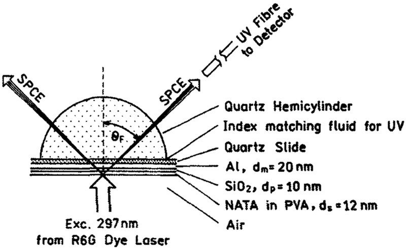
The spin-coated slides were attached to a hemicylindrical prism made of quartz using nonfluorescent index–matching fluid (glycerol, n = 1.44). This combined sample was positioned on a precise rotary stage, which allows excitation and observation at any desired angle relative to the vertical axis around the cylinder (3). For excitation we used the reverse Kretschmann (RK) configuration (Scheme 1). In this configuration the sample was excited from the air, or sample side, which has a refractive index lower than the prism. In this case it is not possible to excite surface plasmons with the incident light. The angle of incidence does not matter, but we used normal incidence.
Scheme 1.
Sample configuration for SPCE of tryptophan. The metallized quartz slide spin coated with PVA-containing NATA was attached to a hemicylindrical quartz prism (the layer thickness is drawn not to the scale). The excited NATA dipoles couple to the surface plasmons, which radiate within the narrow hollow cone at the angle θF. The SPCE radiation is fully p polarized.
The SPCE can be induced also by the evanescent field of surface plasmons created by the incident light. This can be achieved by the excitation through the prism at the SPR angle for the excitation light (Kretschmann configuration). Such excitation provides efficient background rejection and is preferable in SPCE bioassays (18-20). For clarity of presentation we only describe data obtained in the RK configuration in this article.
Observation of the angular distribution of the emission was performed with a 3 mm diameter UV-transmitting fiber, covered with a 500 μm vertical slit, positioned about 15 cm from the sample. This corresponds to an acceptance angle below 0.2°. The output of fiber was directed to a 8000 SLM spectrofluorometer or a 10 GHz frequency domain fluorometer (25).
For excitation, we used the second harmonic (297 nm) from a Rhodamine 6G dye laser. The dye laser was pumped by a mode-locked argon ion laser, 76 MHz-repetition rate, 120 ps half-width and cavity dumped at a 3.8 MHz repetition rate. Scattered light at 297 nm was suppressed by observation through a 0–54 Corning cut-off filter, supported for intensity and lifetime measurements with a 345 nm interference filter.
For lifetime measurements, the multifrequency phase and modulation data were analyzed in terms of the multiexponential model as described previously (26).
RESULTS AND DISCUSSION
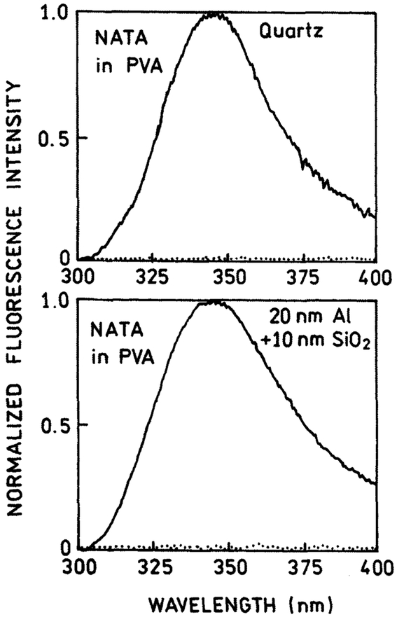
First, we compared the free-space emission of samples prepared on bare quartz and metallized slides. The use of aluminum with fluorescence was not obvious because of observed strong quenching on the aluminum surface (27). To avoid quenching effects we used a 100 Å protective layer of SiO2 added in a vapor deposition procedure. Emission spectra of NATA spin coated from PVA solution are shown in Fig. 1 for quartz (top) and metallized (bottom) substrates. The spectra measured in front-face geometry are essentially identical and characteristic for tryptophan. We were pleasantly surprised by the absence of quenching. The brightness of NATA on the SiO2-protected metallized slide was similar to that on a bare quartz slide. The 100 Å SiO2 layer effectively neutralized NATA quenching by aluminum. The backgrounds (signals from identical slides without NATA) are negligible on either the metallized or unmetallized slide (Fig. 1, dotted lines).
Figure 1.
Emission spectra of NATA spin coated from PVA solution on unmetallized quartz (top) and on aluminum-coated quartz slide (bottom). The fluorescence intensities do not differ for bare quartz and the silica-protected aluminum surface. The dotted lines represent backgrounds from the reference slide without NATA.
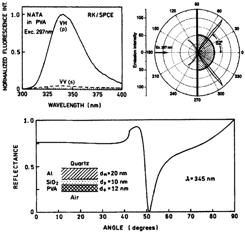
Next, we measured the angular distribution of SPCE of NATA (Fig. 2, top right). The SPCE is narrowly distributed at 52°. The emission spectrum of SPCE (Fig. 2, top left) observed at 52° is characteristic for tryptophan. The SPCE is highly p polarized (P >0.9) independently of polarization of excitation light. The calculated reflectance (Fig. 2, bottom) for the emission wavelength of 345 nm reaches a minimum at 52° for PVA thickness of 12 nm. The calculation was done for the five-phase system shown in the insert in Fig. 2, bottom, and in Scheme 1.
Figure 2.
Top, left: The polarized SPCE of NATA observed at 52°. The 297 nm excitation was vertically (V) polarized. The observation polarizer was either vertically (s) or horizontally (H) oriented (p). The dotted line is the background from the reference slide without NATA, observed through a horizontally oriented polarizer. Top, right: angular distribution of NATA SPCE measured in RK/SPCE configuration. Bottom: the reflectance angular profile calculated for a five-phase system with an assumed PVA thickness of 12 nm.
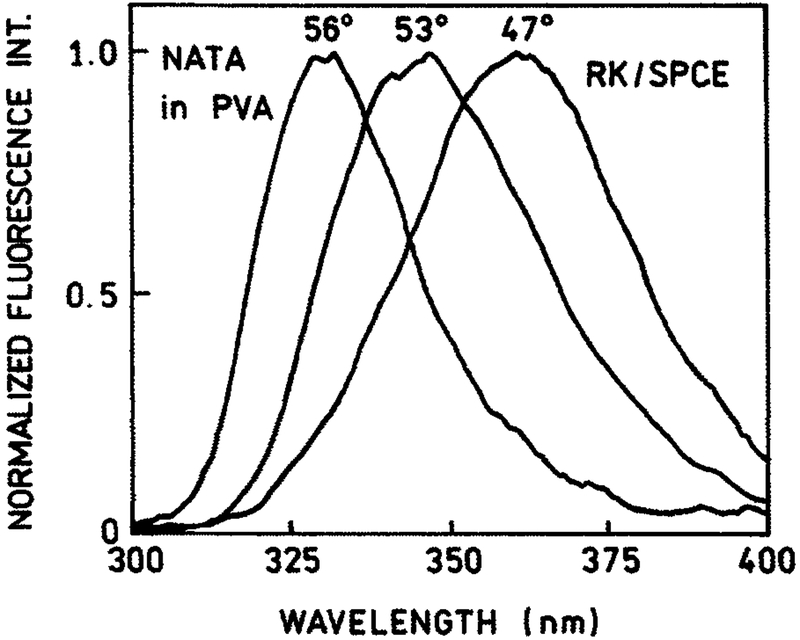
Previously we observed and photographed multicolor rings of SPCE (3), the consequence of the dispersive property of SPR/SPCE. This property is an effect of wavevector matching conditions. To generate the SPR/SPCE, the projection of the wavevector of the incident light on the interface must match the wavevector of surface plasmons (2,22). The recorded spectrum of the NATA SPCE strongly depends on the observation angle (Fig. 3). A 10° change in the observation angle results in a significant, 40 nm shift of the spectrum.
Figure 3.
Observation angle–dependent spectra of NATA SPCE measured in RK/SPCE configuration. About 40 nm/10° resolution is provided by intrinsic dispersive properties of SPCE.
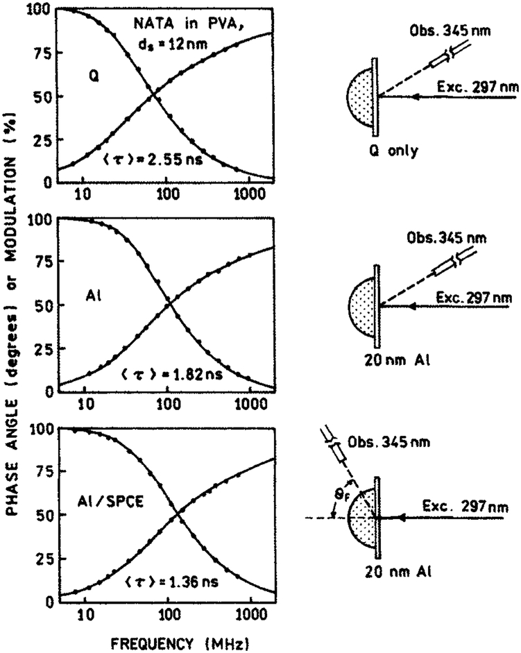
Finally, we investigated the lifetimes of NATA SPCE (Fig. 4). The intensity decays were measured in the frequency domain. Multiexponential parametrization of the decays are summarized in Table 1. The mean lifetime of NATA is only slightly shorter on a metallized slide than on bare quartz (Fig. 4, top and middle), which is consistent with the comparable brightness of these slides. This also shows that 10 nm layer of SiO2 effectively protects the sample against the quenching by the metallic surface. The lifetime of NATA SPCE (Fig. 4, bottom) is decreased by only 25% when compared with a free-space (FS) fluorescence (Fig. 4, middle), which is not a significant lifetime reduction. In earlier studies of fluorophores near metallic particles (28-30), we observed dramatic reduction in lifetimes. Although we do not fully understand how the surface plasmons and fluorophores interact to determine the SPCE, we believe that the reported data can be used by those interested in the SPCE phenomenon.
Figure 4.
Frequency domain lifetimes of NATA spin coated from 0.5% PVA solution in various configurations. Top, on bare quartz; middle, on protected aluminum; bottom, on protected aluminum with RK/SPCE configuration. Only modest changes in lifetimes were observed.
Table 1.
Multiexponential analysis of NATA-doped PVA spin coated on metallized (Al) and unmetallized (Q) quartz slide*
| Conditions | ⟨τ⟩† (ns) |
τ‡ (ns) |
α1 | τ1 (ns) |
α2 | τ2 (ns) |
α3 | τ3 (ns) |
|
|---|---|---|---|---|---|---|---|---|---|
| Q, no Al | 2.55 | 4.02 | 0.335 | 0.50 | 0.398 | 2.30 | 0.267 | 5.49 | 0.8 |
| Al, FS | 1.82 | 2.68 | 0.276 | 0.32 | 0.366 | 1.35 | 0.358 | 3.39 | 0.9 |
| Al, SPCE | 1.36 | 2.29 | 0.362 | 0.28 | 0.486 | 1.44 | 0.152 | 3.69 | 0.9 |
I(t) = ∑i αi exp(−t/τi).
⟨τ⟩ = ∑i αiτi.
, where fi = αiτi/ ∑j αjτj.
CONCLUSIONS
The extension of SPCE to the UV region opens new possibilities to study tryptophan- or tyrosine-containing proteins without labeling with longer wavelength fluorophores.
The use of the 100 Å SiO2 layer not only eliminates metal quenching but also protects the aluminum layer. We were able to wash the sample with water and reuse the metallized slide for another spin coating. The observed brightness and SPCE angle did not differ when the slides were reused. We could not do this with the silver-covered slides, unprotected or protected with 50 Å SiO2.
The intrinsic spectral resolution of directional and polarized SPCE demonstrated in Fig. 3 can be used in miniaturized spectrofluorometers with a minimum amount of optical elements.
Acknowledgements
This work was supported by NIH, the National Center for Research Resources, RR-08119, and Biomolecular Interaction Technologies Center (University of New Hampshire).
Abbreviations:
- FS
free-space
- NATA
N-acetyl-l-tryptophanamide
- PVA
poly(vinyl alcohol)
- RK
reverse Kretschmann configuration
- SPCE
surface plasmon–coupled emission
- SPR
surface plasmon resonance
- SPRA
surface plasmon resonance analysis
- UV
ultraviolet
REFERENCES
- 1.Liebermann T and Knoll W (2000) Surface plasmon field-enhanced fluorescence spectroscopy. Colloids Surf. A 171, 115–130. [Google Scholar]
- 2.Lakowicz JR (2004) Radiative decay engineering 3. Surface plasmon-coupled directional emission. Anal. Biochem 324, 153–169. [DOI] [PMC free article] [PubMed] [Google Scholar]
- 3.Gryczynski I, Malicka J, Gryczynski Z and Lakowicz JR (2004) Radiative decay engineering 4. Experimental studies of surface plasmon-coupled directional emission. Anal. Biochem 324, 170–182. [DOI] [PMC free article] [PubMed] [Google Scholar]
- 4.Lakowicz JR, Malicka J, Gryczynski I and Gryczynski Z (2003) Directional surface plasmon-coupled emission: a new method for high sensitivity detection. Biochem. Biophys. Res. Commun 307, 435–139. [DOI] [PMC free article] [PubMed] [Google Scholar]
- 5.Gryczynski I, Malicka J, Gryczynski Z and Lakowicz JR (2004) Surface plasmon-coupled emission using gold films. J. Phys. Chem. B 108, 12568–12574. [DOI] [PMC free article] [PubMed] [Google Scholar]
- 6.Zhang J, Gryczynski Z and Lakowicz JR (2004) First observation of surface plasmon-coupled electrochemiluminescence, Chem. Phys. Lett 393, 483–487. [DOI] [PMC free article] [PubMed] [Google Scholar]
- 7.Gryczynski I, Malicka J, Gryczynski Z and Lakowicz JR (2004) Surface plasmon-coupled amission: a new method for sensitive fluorescence detection In Topics in Fluorescence Spectroscopy. Metal Enhanced Fluorescence, Vol. 8 (Edited by Lakowicz JR and Geddes CD). Kluwer Academic/Plenum Publishers, New York. (In press) [Google Scholar]
- 8.Calander N (2004) Theory and simulation of surface plasmon-coupled directional emission from fluorophores at planar structures. Anal. Chem 76, 2168–2173. [DOI] [PubMed] [Google Scholar]
- 9.Ekgasit S, Thammacharoen C and Knoll W (2004) Surface plasmon resonance spectroscopy based on evanescent field treatment. Anal. Chem 76, 561–568. [DOI] [PubMed] [Google Scholar]
- 10.Boardman AD, editor (1982) Electromagnetic Surface Modes, 775 p. John Wiley & Sons, New York. [Google Scholar]
- 11.Raether H (1988) Surface Plasmons on Smooth and Rough Surfaces and on Gratings, 136 p. Springer-Verlag, New York. [Google Scholar]
- 12.Liebsh A (1997) Electronic Excitations at Metal Surfaces, 336 p. Plenum Press, New York. [Google Scholar]
- 13.Liedberg B and Lundstrom I (1993) Principles of biosensing with an extended coupling matrix and surface plasmon resonance. Sens. Actuators, B 11, 63–72. [Google Scholar]
- 14.Frey BL, Jordan CE, Komguth S and Corn RM (1995) Control of the specific adsorption of proteins onto gold surface with poly(L-lysine) monolayers. Anal. Chem 67, 4452–4457. [Google Scholar]
- 15.Salamon Z, Macleod HA and Tollin G (1997) Surface plasmon resonance spectroscopy as a tool for investigating the biochemical and biophysical properties of membrane protein systems. I: Theoretical principles. Biochim. Biophys. Acta 1331, 117–129. [DOI] [PubMed] [Google Scholar]
- 16.Peterlinz KA, Georgiadis RM, Heme TM and Tarlov MJ (1997) Observation of hybridization of thiol-tethered DNA using two-color surface plasmon resonance spectroscopy. J. Am. Chem. Soc 119, 3401–3402. [Google Scholar]
- 17.Yu F, Yao D and Knoll W (2003) Surface plasmon field-enhanced fluorescence spectroscopy studies of the interaction between an antibody and its surface-coupled antigen. Anal. Chem 75, 2610–2617. [DOI] [PubMed] [Google Scholar]
- 18.Malicka J, Gryczynski I, Gryczynski Z and Lakowicz JR (2003) DNA hybridization using surface plasmon-coupled emission. Anal. Chem 75, 6629–6633. [DOI] [PMC free article] [PubMed] [Google Scholar]
- 19.Matveeva E, Malicka J, Gryczynski I, Gryczynski Z and Lakowicz JR (2004) Multi-wavelength immunoassays using surface plasmon-coupled emission. Biochem. Biophys. Res. Commun 313, 721–726. [DOI] [PMC free article] [PubMed] [Google Scholar]
- 20.Matveeva E, Gryczynski Z, Gryczynski I and Lakowicz JR (2004) Immunoassays based on directional surface plasmon-coupled emission. J. Immunol. Methods 286, 133–140. [DOI] [PMC free article] [PubMed] [Google Scholar]
- 21.Gryczynski I, Malicka J, Gryczynski Z, Nowaczyk K and Lakowicz JR (2004) Ultraviolet surface plasmon-coupled emission using thin aluminum films. Anal. Chem 76, 4076–4081. [DOI] [PMC free article] [PubMed] [Google Scholar]
- 22.Raether H (1977) Surface plasma oscillations and their applications In Physics of Thin Films, Advances in Research and development, Vol. 9 (Edited by Hass G, Francombe MH and Hoffman RW), pp. 145–261. Academic Press, New York. [Google Scholar]
- 23.Pockrand I (1978) Surface plasma oscillations at silver surfaces with thin transparent and absorbing coatings. Surface Sci. 72, 577–588. [Google Scholar]
- 24.Nelson BP, Frutos AG, Brockman JM and Corn RM (1999) Near-infrared surface plasmon resonance measurements of ultrathin films. 1. Angle shift and SPR imaging experiments. Anal. Chem 71, 3928–3934. [Google Scholar]
- 25.Laczko G, Gryczynski I, Gryczynski Z, Wiczk W, Malak H and Lakowicz JR (1990) A 10-GHz frequency domain fluorometer. Rev. Sci. Instrum 61, 2331–2337. [Google Scholar]
- 26.Lakowicz JR, Gratton E, Laczko G, Cherek H and Limkeman M (1984) Analysis of fluorescence decay kinetics from variable-frequency phase shift and modulation data. Biophys. J 46, 463–477. [DOI] [PMC free article] [PubMed] [Google Scholar]
- 27.Axelrod D, Hellen EH and Fulbright RM (1992) Total internal reflection fluorescence In Topics in Fluorescence Spectroscopy: Biochemical Applications, Vol. 3 (Edited by Lakowicz JR), pp. 289–343. Plenum Press, New York. [Google Scholar]
- 28.Lakowicz JR, Shen Y, D’Auria S, Malicka J, Gryczynski Z and Gryczynski I (2002) Radiative decay engineering 2: Effects of silver island films on fluorescence intensity, lifetimes and resonance energy transfer. Anal. Biochem 301, 261–277. [DOI] [PMC free article] [PubMed] [Google Scholar]
- 29.Malicka J, Gryczynski I, Gryczynski Z and Lakowicz JR (2003) Effects of fluorophore-to-silver distance on the emission of cyanine-dye labeled oligonucleotides. Anal. Biochem 315, 57–66. [DOI] [PMC free article] [PubMed] [Google Scholar]
- 30.Maliwal BP, Malicka J, Gryczynski I, Gryczynski Z and Lakowicz JR (2003) Fluorescence properties of labeled proteins near silver colloid surfaces. Biopolym. (Biospectrosc.) 70, 585–594. [DOI] [PMC free article] [PubMed] [Google Scholar]


