

Abstract
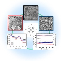
Porphyrin complexes are well‐known for their application in solar‐cell systems and as catalysts; however, their use in electrochemical energy‐storage applications has scarcely been studied. Here, a tetra‐alkenyl‐substituted [5,10,15,20‐tetra(ethynyl)porphinato]copper(II) (CuTEP) complex was used as anode material in a high‐performance lithium‐free CuTEP/PP14TFSI/graphite cell [PP14TFSI=1‐butyl‐1‐methylpiperidinium bis(trifluoromethylsulfonyl)imide]. Thereby, the influence of size and morphology on the electrochemical performance of the cell was thoroughly investigated. Three different nanocrystal CuTEP morphologies, namely nanobricks, nanosheets, and nanoribbons, were studied as anode material, and the best cyclability and highest rate capability were obtained for the nanoribbon samples. A high specific power density of 14 kW kg−1 (based on active material) and excellent rechargeability were achieved with negligible capacity decay over 1000 cycles at a high current density of 5 A g−1. These results indicate that the porphyrin complex CuTEP could be a promising electrode material in high‐performance lithium‐free batteries.
Keywords: alkyne, ionic liquids, lithium-free, porphyrin, rechargeable batteries
Morphology matters: In a Li‐free battery cell with organic electrodes consisting of a tetra‐acetenyl‐substituted porphyrin, the nanobrick‐ and nanoribbon‐morphology porphyrin samples show higher rate cyclability than the nanosheet sample. The organic electrode material demonstrated a specific power density of 14 kW kg−1 and excellent rechargeability.
Lithium‐ion batteries have represented powerful energy‐storage devices since they were commercialized in the early nineties. However, a supply risk is discussed for the Li and Co components should they continue to constitute the central resource in the strongly rising production of electric vehicles, stationary storage, and portable devices. Therefore, it is crucial to explore alternatives for new battery systems that no longer rely on lithium or toxic elements in the electrode/electrolyte composition. Towards this goal, different strategies have been developed to address these challenges, including the exploration of new types of rechargeable batteries based on Na+,1 K+,2 Mg2+,3 Cl−,4 or F−[5] systems, containing cheap and abundant elements.6 Additionally, beyond their chemical nature, the nanostructure of the used electrode materials is also supposed to exhibit significant influence on the energy and power density.7 Molecular materials have been considered as potential electrode materials owing to their tunable capacity, sustainability, and environmental compatibility.8
Although supercapacitors have been shown to deliver very high power densities, the energy densities achieved so far are not yet satisfying.6 Recently, a new concept of dual‐ion batteries (DIBs), in which both cations and anions were used as charge carriers during the electrochemical reactions, was demonstrated and delivered relatively high energy and power densities.9 Generally, in DIBs, the layered graphite cathode is ready for anion intercalation/de‐intercalation whereas cations are deposited/stripped at the metal anode.
Recently, porphyrin‐based materials have attracted considerable interest as a new class of organic electrode materials for electrochemical energy storage.10 As previously shown,10k the porphyrin complex of [5,15‐bis(ethynyl)‐10,20‐diphenylporphinato]copper(II) (CuDEPP) was utilized as both cathode and anode in lithium‐based rechargeable batteries exhibiting both high energy and power densities. Particularly, we found that alkyne substitution on the porphyrin moiety, after an initial electrochemical formation step, leads to a very stable electrode consistency showing an increased stability within 2000 cycles and a capacity retention of 85 %. As an expanded concept, we have now designed and synthesized a tetra‐alkyne‐substituted porphyrin {[5,10,15,20‐tetra(ethynyl)porphinato]copper(II) (CuTEP)} complex with the goal to use it as electrode material and tested the complex in a lithium‐free energy‐storage system.
Electrode materials have been widely studied in inorganic‐based rechargeable batteries. Increased rate capabilities are possible by reducing the diffusion distances of the ions in the electrode and increasing the contact area between the electrode and the electrolyte.11 However, the influence of the morphology of molecular materials on their performance in electrochemical energy‐storage systems has rarely been studied.12 Herein, we investigate the electrochemical performance of anodes made from three different morphologies (nanobricks, nanosheets, and nanoribbons) of the same CuTEP in a lithium‐free device setup with an ionic liquid as electrolyte. On the molecular side, four alkyne groups were introduced into the porphyrin skeleton to maximize the cation–π stacking interactions between the molecules, aiming to develop a highly stable electrode for lithium‐free energy‐storage devices.
The structure of the precursor molecule [5,10,15,20‐tetra(trimethylsilylethynyl)‐porphinato] copper(II) (CuTEP‐TMS), still bearing the trimethylsilyl (TMS) protecting groups, was determined by single‐crystal crystallographic diffraction (Figures S3 and S4, Supporting Information). The molecule crystallizes in a triclinic system with the space group P with a planar aromatic porphyrin ring. Subsequently, CuTEP samples of different nanocrystallinity and morphology were synthesized by controlling the reaction temperature and the solvent composition of the deprotection reaction of the CuTEP‐TMS. Thus, at room temperature, crystals of nanobrick shape of CuTEP (1 a) could be obtained. SEM revealed that the nanobricks had an average diameter of 100 nm in length and a width and thickness of less than 100 nm (Figure 1 top). When the deprotection procedure was performed at lower temperatures (0 °C), samples with the predominant shape of nanosheets (1 b) were obtained, exhibiting a length of approximately 400 nm and a width of more than 100 nm, whereas the thickness remained under 100 nm (Figure 1 middle). Interestingly, at temperatures around room temperature, and after the addition of some drops of water, samples of nanoribbon morphology (1 c) were identified (Figure 1 bottom). The length of the nanoribbons can reach up to 10 μm and their width approximately 100 nm, with a thickness below 100 nm. The three different morphologies of CuTEP nanocrystals are most likely obtained as a result of different kinetics of the alkyne deprotection reaction of the substrate. At low temperature, the reaction rate was decreased, which would induce the crystals to grow larger, leading to nanosheets 1 b.13 Because water can act as proton source in the deprotection reaction, the improved growth conditions lead to nanoribbon structures 1 c.14
Figure 1.
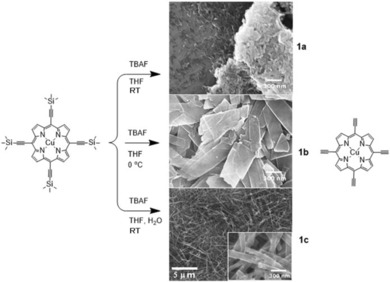
Representation showing the different synthetic protocols leading to the three different samples 1 a, 1 b, and 1 c, the morphologies of which are represented by SEM images in the middle column.
To study the obtained morphologies in more detail, the three samples were characterized by TEM and powder XRD (PXRD). TEM analysis reveals the crystalline nature of all three samples with the presence of lattice fringes visible in low‐dose high‐resolution (HR)TEM (Figure 2). The observed crystal sizes are in accordance with the SEM results. The TEM images and the PXRD results show that the crystallinity increases from 1 a to 1 c. As shown in Figure 2 c, sample 1 c exhibits well‐shaped crystals with a single crystalline nanoribbon structure and an interlayer periodicity of 1.1 nm (inset in Figure 2 c), which is consistent with the first peak of 7.8° in the PXRD result given in Figure 2 d.
Figure 2.
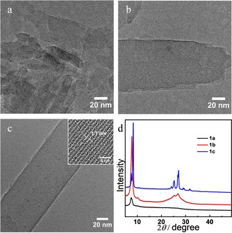
Representative low‐dose HRTEM images of (a) 1 a, (b) 1 b, and (c) 1 c together with (d) the respective PXRD data of 1 a, 1 b, and 1 c.
The electrochemical characteristics of the CuTEP samples with different morphologies were determined in an electrochemical cell configuration of CuTEP/PP14TFSI/graphite [PP14TFSI=1‐butyl‐1‐methylpiperidinium bis(trifluoromethylsulfonyl)imide], in which CuTEP acts as anode coupled with a graphite counter cathode. To prevent solvent co‐insertion into the active anode material, the anhydrous ionic liquid PP14TFSI was used as electrolyte, with only PP14 + and TFSI− acting as charge carriers. The cell configuration during its discharging process is shown in Figure 3, in which the cation PP14 + and the anion TFSI− are proposed to be stored in their respective electrodes.
Figure 3.
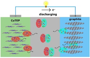
Cell configurations of a CuTEP/PP14TFSI/graphite cell.
To test the reversibility of this lithium‐free cell, cyclic voltammetry (CV) measurements were performed by using graphite as working electrode, CuTEP as counter electrode, and PP14TFSI as electrolyte in the potential range of 4.0–0.0 V at various scan rates (Figure S6, Supporting Information). In the first anodic sweep at a scan rate of 0.2 mV s−1, a wide oxidation peak starting from 2.7 V to a peak value at 3.4 V and reduction peaks at 2.7 and 2.0 V were observed for 1 c (Figure S6 a, Supporting Information), which are associated with the intercalation/de‐intercalation of TFSI− into the graphite cathode.9b, 9c, 9h, 10k From the second to the fifth cycle, the peaks coincide with those in the first cycle, except that the intercalation peak at 3.4 V was shifted to 3.6 V, and the reduction peak at 2.0 V was increased to 2.1 V. At 2.7 V, the TFSI− anions started to intercalate into the graphite crystals, and PP14 + cations interacted with the CuTEP anode. The de‐intercalation peaks at 2.7, 2.0, and 1.1 V in the first cathodic sweep indicate a multistep electrochemical reaction that is potentially correlated with a multistage de‐intercalation process of TFSI− anions from the graphite cathode.9b, 9c As in our previous work based on the similar porphyrin complex CuDEPP,10k, 15 the intercalation/de‐intercalation of TFSI− into the graphite cathode has been proved by XRD and Raman studies, in which a graphite peak was shifted from 2θ=26.48 to 25.38° in XRD,10k and the appearance/disappearance of a new G′ band at 1610 cm−1 was observed in Raman spectra. The operando Raman spectroscopy also showed that the electrochemical activity mainly originates from the conjugated porphyrin ring.15 The intensity of the oxidation peak at 3.6 V generally decreased during the initial five cycles, and the curves were more stable in the following cycles, indicating the self‐stabilization of the cell. This result suggests that CuTEP is activated during the first electrochemical process, which could benefit the following electrochemical reaction. In Figure S6 b–d (Supporting Information), the CV curves of the three cells obtained after initial five cycles at a high scan speed of 5 mV s−1 are presented. As can be seen, the three CV curves for the 1 a, 1 b, and 1 c samples overlap after the initial five cycles, indicating that the cell retains highly reversible capability regardless of the nanostructure of the active electrode material. Stable peaks at 3.2 and 1.5 as well as 2.0 and 1.1 V were clearly observed in a voltage range of 0.0–4.0 V. Notably, sample 1 c shows a slight difference compared with other two cells, with the peaks becoming different in shape. This could be owing to the increased capacitance contribution of 1 c at the electrode surface.
The galvanostatic charge–discharge tests for the CuTEP/PP14TFSI/graphite cell were performed in a voltage range of 4.0–0.0 V at different current rates of 0.5–20 A g−1 (Figure 4 a). Initial discharge capacities of 84, 79, and 87 mAh g−1 were obtained for 1 a, 1 b, and 1 c, respectively, at a current density of 0.5 A g−1 (4.4 C), which are lower than the theoretical value of the CuTEP anode based on a two‐electron transfer [CuTEP→CuTEP2−, 114.5 mAh g−1, calculated according an Equation (1) in the Supporting Information]. An average cell potential of 1.7 V was obtained with similar charge/discharge curves during the electrochemical reaction for the three samples (Figure 4 b). During the first seven cycles, the capabilities slowly reduce to stable capabilities of 78, 72, and 81 mAh g−1 for 1 a, 1 b, and 1 c, respectively, at a current density of 0.5 A g−1. The decrease of capacities can be considered as the stabilization process of the active materials upon the initial electrochemical process, in which the ions open the channel for stable diffusion.10k The nanobrick sample 1 a and the nanoribbon sample 1 c exhibit similar rate capabilities with stable capacities of 43 and 41 mAh g−1 at 20 A g−1, respectively. Notably, a reversible discharge capacity of 43 mAh g−1 was provided within 12 s at a high current density of 20 A g−1 (174 C). If the mass of CuTEP electrode is used for the calculation, this high rate capability corresponds to a high specific power of 14 kW kg−1. When the current density was lowered again to 1 A g−1, the capacities of 1 a and 1 c still reproduced their initial values. However, for the nanosheet morphology 1 b, the capacity decreased from 72 to 27 mAh g−1 when the rate was increased from 0.5 to 20 A g−1. It is clear that both size and morphology of the nanocrystals affect the rate capabilities. Smaller‐sized CuTEP, derived from the sample 1 a, clearly enables a larger reaction interphase and faster PP14 + diffusion kinetics, affording higher capacities and power densities. Moreover, the 1D nanoribbon morphology effectively enhances the ion diffusion and fosters faster charge transport, leading to a higher power density for 1 c.11c, 16
Figure 4.
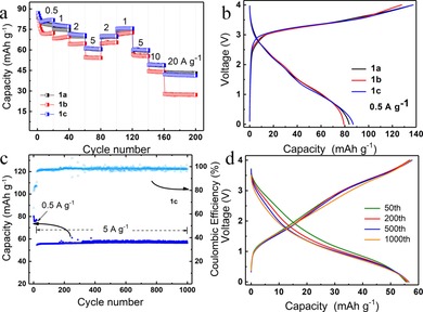
Electrochemical performance of the CuTEP/PP14TFSI/Graphite cell with three different morphology samples of 1 a, 1 b, and 1 c. (a) Rate performance (discharge capacity) of three cells cycled at different current densities. (b) First galvanostatic charge–discharge curves of the three cells at 0.5 A g−1. (c) Cycling performance (discharge capacity) of three cells with 1 a, 1 b, and 1 c. The cells were cycled at 0.5 A g−1 for initial 20 cycles, and at 5 A g−1 for additional 1000 cycles in a voltage range of 4.0–0.0 V. (d) Selected galvanostatic charge–discharge curves of 1 c at 5 A g−1.
The cycling stability of the three samples was tested at a high current rate of 5 A g−1 (44 C) after initial 20 cycles at 0.5 A g−1. Both cells with the samples 1 a or 1 c show a stable discharge capacity of 55 mAh g−1, which was retained for 1000 cycles (Figure S7 a, Supporting Information, and Figure 4 c). Sample 1 b showed a discharge capacity of 56 mAh g−1 in the first cycle at 5 A g−1, which decreased to 45 mAh g−1 after 1000 cycles (Figure S7 b, Supporting Information). Average coulombic efficiencies of 96, 94, and 98 % were reached for 1 a, 1 b, and 1 c, respectively. It is supposed that at smaller crystal size the kinetics of PP14 + interaction with CuTEP electrode will be enhanced. As previously reported,11c, 16 the electrode's nanoribbon morphology could offer a pathway for fast charge extraction without too much recombination losses, and hence can overcome the small‐excitation diffusion‐length issue for organic semiconductors. In addition, the nanoribbons used for electrode preparation could interconnect with each other, enabling fast electron transport,11c, 16 and thereby lower contact resistance in nanoribbons than nanoparticles would be reasonably expected. This could be the reason for better cycle stability in 1 c samples. Meanwhile, relatively unstable coulombic efficiency is observed in sample 1 b after long cycles (Figure S7 b, Supporting Information), which may originate from its poor rate capability at a high current density. Charge and discharge curves of 1 c exhibit slope characteristics indicating that no two‐phase system is involved in the charge storage (Figure 4 d). Compared with the charge/discharge curve in the first cycle (Figure 4 b), a slight discharge potential decay was noticed during the cycling, implying that the polarization might increase upon long‐term cycling at a high current rate. In contrast to our previous work,9a, 10k electrodes based on the newly synthesized [5,10,15,20‐tetra(ethynyl)porphinato]copper(II) complex show an ultrafast charge and discharge capability and good cycling stability even at high current densities. To further identify the capacity contribution of carbon black (CB), a blank reference CB/PP14TFSI/graphite cell was fabricated. At a current density of 0.5 A g−1, its discharge capacity rapidly decreased from 43 to 19 mAh g−1 in the first 50 cycles. In the following cycles at a high current density of 5 A g−1, a negligible capacity of 4 mAh g−1 was obtained (Figure S8, Supporting Information), which is much lower than for the CuTEP electrodes. These results prove that the main capacity contribution comes from the CuTEP material.
In summary, a new tetra‐acetenyl‐substituted copper(II) porphyrin complex CuTEP has been proposed as an anode material in a Li‐free CuTEP/PP14TFSI/graphite cell [PP14TFSI=1‐butyl‐1‐methylpiperidinium bis(trifluoromethylsulfonyl)imide]. By reducing the preparation temperature during deprotection, the size of nanocrystals of CuTEP can be enlarged, ranging from nanobrick (1 a) to nanosheet (1 b) samples. Addition of water leads to formation of the nanoribbon product (1 c). All three different morphologies show good electrochemical energy‐storage properties, that is, stable cyclability and high power density. The 1 a and 1 c show an improved rate capacity and cycling stability compared with 1 b. For the 1 a and 1 c, discharge capacities of 43 and 41 mAh g−1 at a high current density of 20 A g−1 could be obtained, providing a maximum specific power of 14 kW kg−1 (based on active material). A discharge capacity of 55 mAh g−1 was obtained at 5 A g−1 without observable capacity decrease after 1000 cycles. Future work will focus on the further optimization of the electrode/electrolyte materials of the battery systems. The battery chemistry in this study on porphyrin‐based organic materials may lead to the development of flexible energy‐storage devices with high power density.
Conflict of interest
The authors declare no conflict of interest.
Supporting information
As a service to our authors and readers, this journal provides supporting information supplied by the authors. Such materials are peer reviewed and may be re‐organized for online delivery, but are not copy‐edited or typeset. Technical support issues arising from supporting information (other than missing files) should be addressed to the authors.
Supplementary
Acknowledgements
This study is supported by MagSiMal project (03XP0208 H) of German Ministry of Research and Education (BMBF), the “Cluster of Excellence” POLiS of the Deutsche Forschungsgemeinschaft (project‐number 390874152), China Scholarship Council (CSC) and National Natural Science Foundation of China (21805236) and Fundamental Research Funds of Xiangtan University (18QDZ14). The authors acknowledge the KNMF facility (KIT, Germany). This work contributes to the research performed at CELEST (Center for Electrochemical Energy Storage Ulm‐Karlsruhe).
Z. Chen, P. Gao, W. Wang, S. Klyatskaya, Z. Zhao-Karger, D. Wang, C. Kübel, O. Fuhr, M. Fichtner, M. Ruben, ChemSusChem 2019, 12, 3737.
Contributor Information
Prof. Dr. Maximilian Fichtner, Email: m.fichtner@kit.edu.
Prof. Dr. Mario Ruben, Email: mario.ruben@kit.edu.
References
- 1.
- 1a. Dunn B., Kamath H., Tarascon J. M., Science 2011, 334, 928–935; [DOI] [PubMed] [Google Scholar]
- 1b. Yabuuchi N., Kubota K., Dahbi M., Komaba S., Chem. Rev. 2014, 114, 11636–11682; [DOI] [PubMed] [Google Scholar]
- 1c. Cheng F., Liang J., Tao Z., Chen J., Adv. Mater. 2011, 23, 1695–1715. [DOI] [PubMed] [Google Scholar]
- 2.
- 2a. Eftekhari A., Jian Z., Ji X., ACS Appl. Mater. Interfaces 2017, 9, 4404–4419; [DOI] [PubMed] [Google Scholar]
- 2b. Wessells C. D., Peddada S. V., Huggins R. A., Cui Y., Nano Lett. 2011, 11, 5421–5425; [DOI] [PubMed] [Google Scholar]
- 2c. Jian Z., Luo W., Ji X., J. Am. Chem. Soc. 2015, 137, 11566–11569. [DOI] [PubMed] [Google Scholar]
- 3.
- 3a. Muldoon J., Bucur C. B., Gregory T., Chem. Rev. 2014, 114, 11683–11720; [DOI] [PubMed] [Google Scholar]
- 3b. Zhao-Karger Z., Fichtner M., MRS Commun. 2017, 7, 770–784; [Google Scholar]
- 3c. Zhao-Karger Z., Zhao X. Y., Wang D., Diemant T., Behm R. J., Fichtner M., Adv. Energy Mater. 2015, 5, 1401155. [Google Scholar]
- 4.
- 4a. Gao P., Reddy M. A., Mu X., Diemant T., Zhang L., Zhao-Karger Z., Chakravadhanula V. S., Clemens O., Behm R. J., Fichtner M., Angew. Chem. Int. Ed. 2016, 55, 4285–4290; [DOI] [PubMed] [Google Scholar]; Angew. Chem. 2016, 128, 4357–4362; [Google Scholar]
- 4b. Zhao X., Zhao-Karger Z., Wang D., Fichtner M., Angew. Chem. Int. Ed. 2013, 52, 13621–13624; [DOI] [PubMed] [Google Scholar]; Angew. Chem. 2013, 125, 13866–13869; [Google Scholar]
- 4c. Gschwind F., Euchner H., Rodriguez-Garcia G., Eur. J. Inorg. Chem. 2017, 2784–2799. [Google Scholar]
- 5.
- 5a. Gschwind F., Rodriguez-Garcia G., Sandbeck D. J. S., Gross A., Weil M., Fichtner M., Hormann N., J. Fluorine Chem. 2016, 182, 76–90; [Google Scholar]
- 5b. Rongeat C., Reddy M. A., Diemant T., Behm R. J., Fichtner M., J. Mater. Chem. A 2014, 2, 20861–20872; [Google Scholar]
- 5c. Thieu D. T., Hammad M., Bhatia H., Diemant T., Chakravadhanula V. S. K., Behm R. J., Kubel C., Fichtner M., Adv. Funct. Mater. 2017, 27, 1701051. [Google Scholar]
- 6. Simon P., Gogotsi Y., Nat. Mater. 2008, 7, 845–854. [DOI] [PubMed] [Google Scholar]
- 7.
- 7a. Aricò A. S., Bruce P., Scrosati B., Tarascon J. M., van Schalkwijk W., Nat. Mater. 2005, 4, 366–377; [DOI] [PubMed] [Google Scholar]
- 7b. Mahmood N., Tang T., Hou Y., Adv. Energy Mater. 2016, 6, 1600374. [Google Scholar]
- 8.
- 8a. Schon T. B., McAllister B. T., Li P. F., Seferos D. S., Chem. Soc. Rev. 2016, 45, 6345–6404; [DOI] [PubMed] [Google Scholar]
- 8b. Song Z., Zhou H., Energy Environ. Sci. 2013, 6, 2280; [Google Scholar]
- 8c. Liang Y., Tao Z., Chen J., Adv. Energy Mater. 2012, 2, 742–769. [Google Scholar]
- 9.
- 9a. Fan J., Zhang Z., Liu Y., Wang A., Li L., Yuan W., Chem. Commun. 2017, 53, 6891–6894; [DOI] [PubMed] [Google Scholar]
- 9b. Rothermel S., Meister P., Schmuelling G., Fromm O., Meyer H.-W., Nowak S., Winter M., Placke T., Energy Environ. Sci. 2014, 7, 3412–3423; [Google Scholar]
- 9c. Placke T., Rothermel S., Fromm O., Meister P., Lux S. F., Huesker J., Meyer H. W., Winter M., J. Electrochem. Soc. 2013, 160, A1979–A1991; [Google Scholar]
- 9d. Placke T., Fromm O., Lux S. F., Bieker P., Rothermel S., Meyer H.-W., Passerini S., Winter M., J. Electrochem. Soc. 2012, 159, A1755–A1765; [Google Scholar]
- 9e. Placke T., Bieker P., Lux S. F., Fromm O., Meyer H.-W., Passerini S., Winter M., Z. Phys. Chem. 2012, 226, 391–407; [Google Scholar]
- 9f. Jiang C., Fang Y., Lang J., Tang Y., Adv. Energy Mater. 2017, 7, 1700913; [Google Scholar]
- 9g. Nishide H., Suga T., Electrochem. Soc. Interface 2005, 14, 32–36; [Google Scholar]
- 9h. Maruyama H., Nakano H., Nakamoto M., Sekiguchi A., Angew. Chem. Int. Ed. 2014, 53, 1324–1328; [DOI] [PubMed] [Google Scholar]; Angew. Chem. 2014, 126, 1348–1352; [Google Scholar]
- 9i. Suga T., Sugita S., Ohshiro H., Oyaizu K., Nishide H., Adv. Mater. 2011, 23, 751–754. [DOI] [PubMed] [Google Scholar]
- 10.
- 10a. Shin J. Y., Yamada T., Yoshikawa H., Awaga K., Shinokubo H., Angew. Chem. Int. Ed. 2014, 53, 3096–3101; [DOI] [PubMed] [Google Scholar]; Angew. Chem. 2014, 126, 3160–3165; [Google Scholar]
- 10b. Xu F., Xu H., Chen X., Wu D., Wu Y., Liu H., Gu C., Fu R., Jiang D., Angew. Chem. Int. Ed. 2015, 54, 6814–6818; [DOI] [PubMed] [Google Scholar]; Angew. Chem. 2015, 127, 6918–6922; [Google Scholar]
- 10c. Zhang H., Zhang Y., Gu C., Ma Y., Adv. Energy Mater. 2015, 5, 1402175; [Google Scholar]
- 10d. Yang H., Zhang S., Han L., Zhang Z., Xue Z., Gao J., Li Y., Huang C., Yi Y., Liu H., Li Y., ACS Appl. Mater. Interfaces 2016, 8, 5366–5375; [DOI] [PubMed] [Google Scholar]
- 10e. Kumar N. A., Gaddam R. R., Suresh M., Varanasi S. R., Yang D., Bhatia S. K., Zhao X. S., J. Mater. Chem. A 2017, 5, 13204–13211; [Google Scholar]
- 10f. Kong L., Li B.-Q., Peng H.-J., Zhang R., Xie J., Huang J.-Q., Zhang Q., Adv. Energy Mater. 2018, 8, 1800849; [Google Scholar]
- 10g. Li B. Q., Zhang S. Y., Kong L., Peng H. J., Zhang Q., Adv. Mater. 2018, 30, 1707483; [DOI] [PubMed] [Google Scholar]
- 10h. Li B.-Q., Zhang S.-Y., Wang B., Xia Z.-J., Tang C., Zhang Q., Energy Environ. Sci. 2018, 11, 1723–1729; [Google Scholar]
- 10i. Ma T., Pan Z., Miao L., Chen C., Han M., Shang Z., Chen J., Angew. Chem. Int. Ed. 2018, 57, 3158–3162; [DOI] [PubMed] [Google Scholar]; Angew. Chem. 2018, 130, 3212–3216; [Google Scholar]
- 10j. Zhao-Karger Z., Gao P., Ebert T., Klyatskaya S., Chen Z., Ruben M., Fichtner M., Adv. Mater. 2019, 31, 1806599; [DOI] [PubMed] [Google Scholar]
- 10k. Gao P., Chen Z., Zhao-Karger Z., Mueller J. E., Jung C., Klyatskaya S., Diemant T., Fuhr O., Jacob T., Behm R. J., Ruben M., Fichtner M., Angew. Chem. Int. Ed. 2017, 56, 10341–10346; [DOI] [PubMed] [Google Scholar]; Angew. Chem. 2017, 129, 10477–10482. [Google Scholar]
- 11.
- 11a. Liu J., Lu P.-J., Liang S., Liu J., Wang W., Lei M., Tang S., Yang Q., Nano Energy 2015, 12, 709–724; [Google Scholar]
- 11b. Lin J., Peng Z., Xiang C., Ruan G., Yan Z., Natelson D., Tour J. M., ACS Nano 2013, 7, 6001–6006; [DOI] [PubMed] [Google Scholar]
- 11c. Wei L., Wang Y., Wang Y., Xu M., Zheng G., J. Colloid Interface Sci. 2014, 432, 297–301. [DOI] [PubMed] [Google Scholar]
- 12. Wang Y., Ding Y., Pan L., Shi Y., Yue Z., Shi Y., Yu G., Nano Lett. 2016, 16, 3329–3334. [DOI] [PubMed] [Google Scholar]
- 13.
- 13a. Song J. H., Kim Y. J., Kim J. S., Curr. Appl. Phys. 2006, 6, 216–218; [Google Scholar]
- 13b. Lin C. C., Ho J. M., Wu M. S., Powder Technol. 2015, 274, 441–445; [Google Scholar]
- 13c. Pu Y. C., Song F., Zhang W. C., Lindley S., Adams S., Zhang J. Z., Part. Part. Syst. Charact. 2017, 34, 1600255. [Google Scholar]
- 14. Mohanty P., Landskron K., New J. Chem. 2010, 34, 215–220. [Google Scholar]
- 15. Lin X.-M., Wu D.-Y., Gao P., Chen Z., Ruben M., Fichtner M., Chem. Mater. 2019, 31, 3239–3247. [Google Scholar]
- 16. Song J. M., Lin Y. Z., Yao H. B., Fan F. J., Li X. G., Yu S. H., ACS Nano 2009, 3, 653–660. [DOI] [PubMed] [Google Scholar]
Associated Data
This section collects any data citations, data availability statements, or supplementary materials included in this article.
Supplementary Materials
As a service to our authors and readers, this journal provides supporting information supplied by the authors. Such materials are peer reviewed and may be re‐organized for online delivery, but are not copy‐edited or typeset. Technical support issues arising from supporting information (other than missing files) should be addressed to the authors.
Supplementary