

Abstract
Objectives
In intrathecal drug delivery, visualization of the device has been performed with plain radiography. However, the visibility of the related structures can be problematic. In troubleshooting, after the contrast material injection via the catheter access port, a computed tomography (CT) scan has been used. In troubleshooting, we also used a non‐contrast CT scan with 2D and 3D reconstructions. With the current phantom study, we aimed to obtain high‐resolution imaging of a poor opaque catheter with the use of a low‐dose single‐energy 2D and 3D CT scan with limited radiation exposure as a substitute for plain radiography.
Materials and Methods
The catheter was placed into a fatty substance and mounted on an anthropomorphic abdomen phantom followed by CT with varying kVp settings and with added tin beam filtering. Dose levels corrected based on the spinal catheter tip on T8 would result in a calculated effective dose in the range of the mSv's calculated for the plain x‐ray examination.
Results
Ultimately, Sn100 kVp has the best trade‐off between visibility, artifacts, and noise for a fixed dose. Although 3D VRT imaging was challenging at this low dose level, we could make a full evaluation possible with complementary 2D projections.
Conclusions
We could correctly identify the catheter and related structures, which supports the investigation of this in vivo and side‐by‐side evaluation with plain radiography. If found superior, then this technique may be able to replace plain radiography, while providing better visualization and acceptable radiation exposure.
Conflict of Interest
Dr. Delhaas reports personal fees from Medtronic Inc., as a previous consultant, outside the submitted work; Prof. van der Lugt reports grants from GE Healthcare, Siemens, Stryker, Medtronic, and Penumbra outside the submitted work.
Keywords: Catheter opacity, CT 2D/3D reconstructions, intrathecal drug delivery, phantom study
INTRODUCTION
Intrathecal drug administration using the implantable SynchroMed II delivery device (Medtronic Inc., MN, USA) is well‐established in treating intractable pain, spasticity, and dystonia. Despite generally favorable and safe outcomes and continuous advancements in manufacturing technology, adverse events related to the pump and catheter still occur.
Visualization of the pump and catheter is performed after device implantation and in troubleshooting to confirm the correct pump and catheter positioning. Historically, the cornerstone for the diagnosis of a catheter‐related problem was plain radiography, which was in most cases, but not in all, acceptable in the older catheter types 1. However, the opacity of the latest developed clinically used Ascenda catheter is more problematic (Figs. 1a, 5c) 1.
Figure 1.
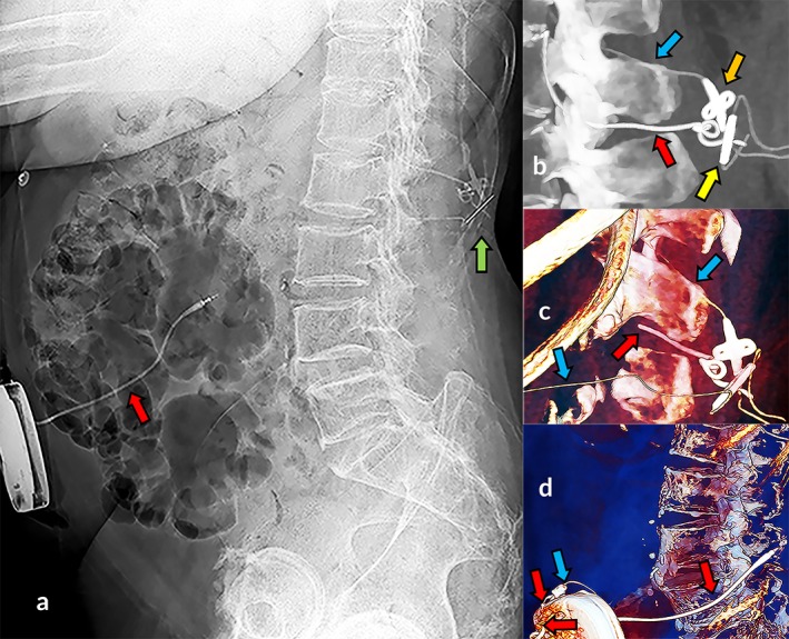
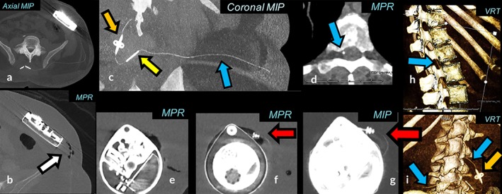
Visibility of spinal catheter with CT in troubleshooting. Plain radiography: invisible Ascenda catheter and visible type 8731SC catheter segment (a, red arrow), and dorsal to the spine several hardly recognized structures of both catheters on (a, green arrow). Zoomed two‐dimensional maximum intensity projection (b) and three‐dimensional volume rendered images (c, d) revealed visible Ascenda structures: catheter (blue arrow), catheter‐catheter connector (yellow arrow), fixation anchor (orange arrow), as well as retained 8731SC catheter parts (red arrow).
Figure 5.
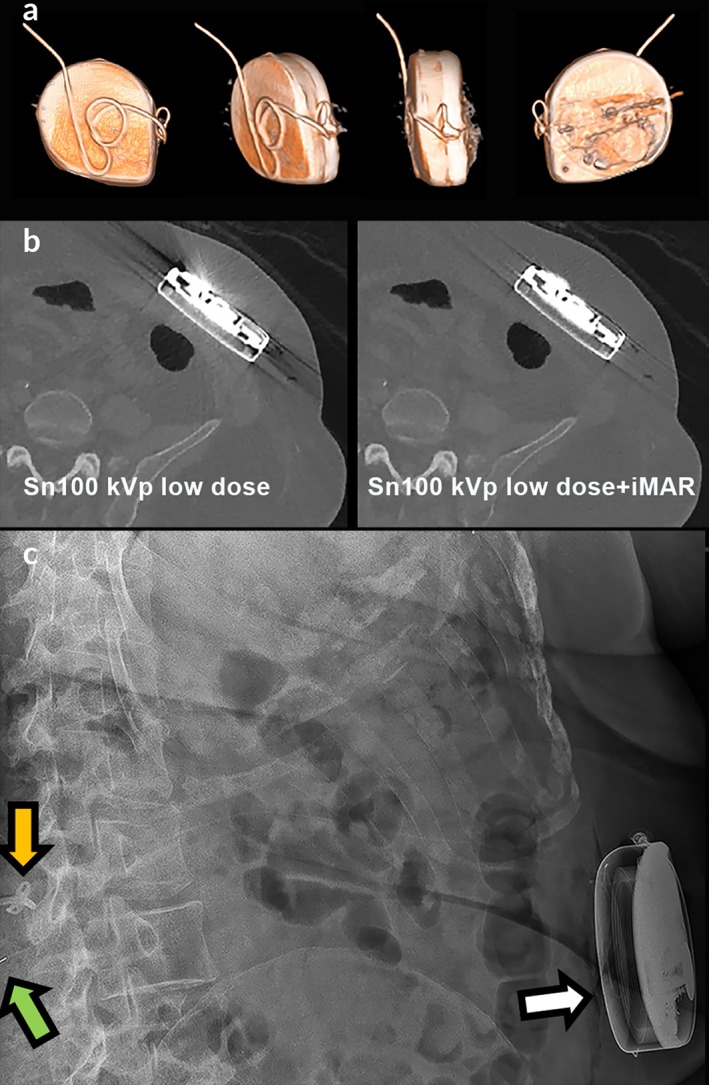
Surplus catheter behind the pump. 3D VRT reconstruction (a) with iterative metal artifact reduction reconstruction algorithm (b) showing a normal course of surplus catheter length behind the pump, which is invisible on plain radiography (c, white arrow) and CT (b). The Ascenda catheter cannot be followed along its track on plain radiography (c); the only structures visible are the catheter‐catheter connector (green arrow) and the fixation anchor (orange arrow).
In troubleshooting, we, therefore, extended the plain radiography with catheter access port (CAP) CT myelography with high‐resolution two‐ (2D) (Fig. 1b) and three‐dimensional (3D) (Fig. 1c,d) 2, 3, 4, 5, 6, 7, 8, reconstructions based on maximum intensity projection (MIP) 9, multiplanar reformation (MPR) 9, and volume rendering techniques (VRTs) 9. With this approach, we could provide optimal visualization of the entire catheter pathway (Fig. 1b–d) 7 and reduce beam‐hardening artifacts around the implanted titanium pump. Normally, compared to plain radiography, CT has the disadvantage of an increased radiation dose. With the current phantom study, we aimed to obtain high‐resolution imaging of the Ascenda catheter with the use of a low‐dose single‐energy 2D and 3D CT scan with limited radiation exposure as a substitute for plain radiography. Based on this experience we now intend to replace plain radiography by CT in all cases where imaging of the pump and catheter is needed.
MATERIALS AND METHODS
We tested the visualization of the Ascenda catheter placed into a fatty substance and mounted on an Anthropomorphic Abdomen Phantom (QRM GmbH, Moehrendorf, Germany) with a 2.5 cm fat equivalent extension ring (Fig. 2). We performed a low‐dose single‐energy spiral CT scan (SECT) using a multi‐slice CT scanner (SOMATOM Drive VA62A, Siemens Healthcare GmbH, Erlangen, Germany). Scans were performed with varying kVp settings (80, 100, and 140) and with added tin (Sn) beam filtering (Sn100, Sn140) to evaluate a trade‐off between the catheter visibility, the pump beam‐hardening artifacts, and the x‐ray energy level. Because a Sn filter at 80 and 120 kVp is not available, this setting was not used. By adapting the tube load (in mAs), three scans per kVp setting were performed with three fixed values of the dose length product (DLP) for a 20 cm scan range on the phantom: 15, 30, and 60 mGy × cm. These dose levels, corrected for an average 50 cm scan range based on the spinal catheter tip on T8, would result in a calculated effective dose of, respectively, 0.6, 1.1, and 2.3 mSv. These values are approximately less than, virtually equal to, and more than the dose level of 0.7 mSv previously used in plain x‐ray examination of the old catheters in a standard patient.
Figure 2.
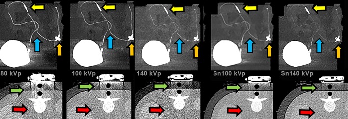
CT imaging of a catheter mounted on a phantom with extension ring. Ascenda intrathecal catheter in a fatty substance, visible catheter (blue arrow) with fixation anchor (orange arrow) and catheter‐catheter connector on CT 2D MIP images (yellow arrow). A dose of 80 kVp showed most artifacts (beam hardening [green arrow] and noise of phantom body [red arrow]), 100 kVp artifacts less but still present, 140 kVp reduced beam hardening, noise still present, Sn100 kVp strongly reduced artifacts, and Sn140 kVp minimum artifacts but more noise visible and less catheter visibility.
RESULTS
The protocol with a DLP of 30 mGy × cm has an optimum radiation dose level for all kVp settings because the lowest dose resulted in poor visualization and the highest dose resulted in better visualization than needed. A low energy level of 80 kVp had the highest contrast between the catheter and the surrounding tissue, benefiting catheter visualization, but also had the highest level of beam‐hardening artifacts around the pump. The highest energy level of 140 kVp with added Sn filtering had minimal artifacts, but the reduced contrast caused the catheter visibility to become insufficient. Sn filtering resulted in increased dose efficiency with an improved signal‐to‐noise ratio for the same dose in this phantom study (Fig. 2, 100 kVp vs. Sn100 kVp). Ultimately, Sn100 kVp has the best trade‐off between visibility, artifacts, and noise for a fixed dose (Fig. 2). The clinical CT settings are summarized in Fig. 3. Although 3D VRT imaging was challenging at this low dose level, we could make a full evaluation possible with complementary 2D MIP and MPR projections (Figs. 4 and 5). However, with Sn filter, not all metal‐related artifacts that obscure adjacent tissues could be suppressed. Additional improvement in visualization of the pump, proximal catheter and surrounding soft‐tissue structures 10 could be achieved with the use of metal artifact reduction (MAR) algorithm (iMAR [Siemens], Smart‐MAR [GE Healthcare], O‐MAR [Philips], SEMAR [Canon]) 11 which suppresses the scattering in the images caused by the metal pump (Fig. 5).
Figure 3.
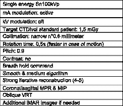
Single energy protocol low‐dose CT.
Figure 4.
Low‐dose SECT 2D/3D imaging. Sn100 kVp scan with an effective dose 0.8 mSv. A combination of MPR, MIP, and VRT is used to follow the Ascenda catheter (blue arrow), pump‐catheter connection (red arrow), catheter‐catheter connection (yellow arrow), fixation anchor (orange arrow) and pump. Postoperative air visible with MPR (b, white arrow), invisible with MIP (a) and is a potential cause of artifacts in MIP and VRT which may mimic a pump‐catheter disconnection.
DISCUSSION
A low‐dose CT scan for visualization of the pump and catheter with an equivalent radiation dose to conventional plain radiography is feasible. To extend CT with 2D and 3D reconstructions will be of value for the postoperative evaluation of a normal drug delivery system and for the proper diagnosis in troubleshooting. The optimal DLP was 30 mGy × cm with radiation exposure of 1.1 mSv for a scan range of 50 cm, which is close to the dose of plain radiography images. The dose of plain radiography in our center was approximately 0.7 mSv, although a value of 3.6 mSv for at least six needed plain radiography images has been reported 12. We prefer the use of 100 kVp with the Sn filter. The benefit of the filter use is the reduction of beam‐hardening artifacts originating from the metal pump, but not all metal‐related artifacts that obscure adjacent tissues can be suppressed. Application of a MAR algorithm can thereby be of help. When Sn filter is used, the obtained narrowed and increased mean energy level of the x‐ray tube spectrum will create an improvement in the overall image quality 13. The choice for an increase in kVp resulted in a decrease in the contrast between the catheter and the surrounding tissue, which is accompanied by a reduction in artifacts.
Furthermore, the choice for Sn filtering resulted in an additional decrease in the contrast between the catheter and the surrounding tissue, which is accompanied by an increased signal‐to‐noise ratio. Another disadvantage is the need for higher mAs settings, which may limit the increase of scan speed if the patient is moving, and which is not uncommon in our spastic patient group. In the relatively small phantom, we could omit the beam hardening with Sn100 kVp (Fig. 2). In obese patients or with the hindrance of upper extremity contractures, higher radiation dose values may be needed. This objective could be automatically realized with the automatic mA exposure modulation setup of a CT scanner. For a definite conclusion and the application of CT in vivo using CT scanners from different vendors, imaging protocols per scanner should be developed.
CONCLUSION
The positive findings of our phantom study in correctly identifying the catheter components supports the in vivo evaluation and a side‐by‐side comparison with plain radiography. If found superior, then this technique may be able to replace plain radiography, while providing better visualization and acceptable radiation exposure.
Authorship Statement
Both Dr. Delhaas and Prof. van der Lugt designed and conducted the study. Dr. Delhaas prepared the manuscript with important intellectual input from Prof. van der Lugt. Both authors approved the final manuscript and had complete access to the study data. The authors would like to thank Dr. van Straten, Mr. Dijkshoorn and Mr.de Man for their support.
COMMENTS
Whilst it is easy to diagnose there is a problem with an intrathecal pump/catheter unit (increased pain, increased spasticity) it can sometimes be far from easy to separate underdosing from treatment refractoriness or pump malfunction from catheter fracture. This can require a review of the pump residual returns over time, a fluoroscopy rotor study, a side port fluid access withdrawal test, side port catheter dye study etcetera. Troubleshooting algorithms and logic are critical for establishing the correct diagnosis.
A catheter dye study is often needed. This can be complex especially when no aspiration of fluid from the side port is forthcoming as in that scenario a bolus of drug (baclofen or morphine) will be delivered to the patient before the radiological dye enters the CSF and this may have clinical consequences for the patient and mandate in hospital observation.
An imaging assessment system that could replace this process would be a welcome advance in clinical care. It would allow planning of definitive surgical replacement or repair based on imaging results without having accessed the side port.
From here clinical studies should follow. The proof is in the pudding that new imaging modalities should provide more information more reliably and reduce complications. These CT techniques may very well do that.
Marc Russo, MBBS
Sydney, Australia
***
Short article but very clear in defining the problem of not being to visualize catheter continuity without additional expense and hassle of doing a pump side port myelogram.
Timothy Lubenow, MD
Chicago, IL, USA
Comments not included in the Early View version of this paper.
For more information on author guidelines, an explanation of our peer review process, and conflict of interest informed consent policies, please go to http://www.wiley.com/WileyCDA/Section/id-301854.html
Source(s) of financial support: None.
REFERENCES
- 1. Delhaas EM, Harhangi BS, Frankema SPG, Huygen F, van der Lugt A. Plain radiography in patients treated with intrathecal drug delivery using an implantable pump device. Insight Imag 2017;8:499–511. [DOI] [PMC free article] [PubMed] [Google Scholar]
- 2. Abousamra O, Rogers KJ, McManus M, Miller F, Sees JP. Evaluation of intrathecal baclofen delivery system malfunction by computed tomography scan. Dev Med Child Neurol 2016;58:409–415. [DOI] [PubMed] [Google Scholar]
- 3. Schapiro A, Racadio J, Kinnett D, Maugans T. Combined C‐arm fluoroscopy and C‐arm cone beam computed tomography for the evaluation of patients with possible intrathecal baclofen delivery system malfunctions. Neurosurgery 2011;69:27–33. discussion 33. [DOI] [PubMed] [Google Scholar]
- 4. Miracle AC, Fox MA, Ayyangar RN, Vyas A, Mukherji SK, Quint DJ. Imaging evaluation of intrathecal baclofen pump‐catheter systems. Am J Neuroradiol 2011;32:1158–1164. [DOI] [PMC free article] [PubMed] [Google Scholar]
- 5. Dvorak EM, McGuire JR, Nelson MES. Incidence and identification of Intrathecal baclofen catheter malfunction. PM R 2010;2:751–756. [DOI] [PubMed] [Google Scholar]
- 6. Ellis JA, Leung R, Winfree CJ. Spinal infusion pump‐catheter leak detected by high‐resolution 3D computed tomography. J Neurosurg Spine Nov 2011;15:555–557. [DOI] [PubMed] [Google Scholar]
- 7. Morgalla M, Fortunato M, Azam A, Tatagiba M, Lepski G. High‐resolution three‐dimensional computed tomography for assessing complications related to Intrathecal drug delivery. Pain Physician 2016;19:E775–E780. [PubMed] [Google Scholar]
- 8. Dupoiron D, Carvajal G. High‐resolution three‐dimensional computed tomography reconstruction as first‐line imaging modality to detect Intrathecal catheter malfunction. Neuromodulation 2018;21:717–720. [DOI] [PubMed] [Google Scholar]
- 9. Dalrymple NC, Prasad SR, Freckleton MW, Chintapalli KN. Informatics in radiology (infoRAD): Introduction to the language of three‐dimensional imaging with multidetector CT. Radiographics 2005;25:1409–1428. [DOI] [PubMed] [Google Scholar]
- 10. Kotsenas AL, Michalak GJ, DeLone DR et al. CT metal artifact reduction in the spine: Can an iterative reconstruction technique improve visualization? Am J Neuroradiol 2015;36:2184–2190. [DOI] [PMC free article] [PubMed] [Google Scholar]
- 11. Greffier J, Larbi A, Frandon J, Daviau PA, Beregi JP, Pereira F. Influence of iterative reconstruction and dose levels on metallic artifact reduction: A phantom study within four CT systems. Diagn Interv Imaging 2019;100:269–277. [DOI] [PubMed] [Google Scholar]
- 12. Vilar‐Palop J, Vilar J, Hernandez‐Aguado I, Gonzalez‐Alvarez I, Lumbreras B. Updated effective doses in radiology. J Radiol Prot 2016;36:975–990. [DOI] [PubMed] [Google Scholar]
- 13. Gordic S, Morsbach F, Schmidt B et al. Ultralow‐dose chest computed tomography for pulmonary nodule detection: First performance evaluation of single energy scanning with spectral shaping. Investig Radiol 2014;49:465–473. [DOI] [PubMed] [Google Scholar]