

Abstract
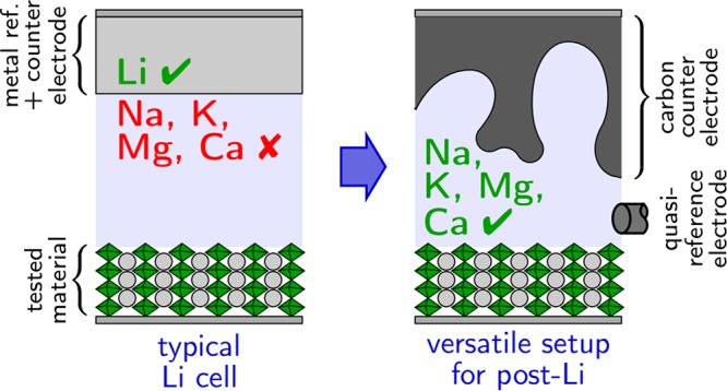
While less mature than the Li-ion battery, technologies based on Na, K, Mg, and Ca are attracting more and more attention from the battery community. New material (cathode, anode, or electrolyte) testing for these post-Li systems commonly involves the use of an electrochemical setup called a half-cell in which metal counter and reference electrodes are used. Here we first describe the different issues that become critical when moving away from Li with respect to the cell hardware (cell design, current collector, separator, insulator) and the nature of the counter and reference electrodes. Workarounds are given, and a versatile setup is proposed to run reliable electrochemical tests for post-Li battery materials in general, in a broad range of electrolyte compositions.
Introduction
Our modern society is battery dependent! The continuous growth of the worldwide battery market (around 70 billion US$ in 2016) is galvanized by the cost decrease (in $/kWh) of the Li-ion technology which has been divided by a factor of 10 since its first commercialization by Sony in 1991.1 However, the Li-ion battery is slowly but surely reaching its limits (both in terms of energy density and cost reduction), and controversial debates on lithium supply cannot be ignored.2 Several other battery chemistries are being developed aiming at reaching the critical figures of merit in terms of energy density and affordability (300 Wh/kg and 100 $/kWh, respectively) for automotive application. Among them, sodium (Na), calcium (Ca), and magnesium (Mg) based batteries are potentially interesting candidates. Indeed, Na-ion batteries have prospects for being cheaper and already demonstrated energy density and power performances close to the ones of their lithium analogues. A technology based on Ca or Mg metal anodes would bring a breakthrough in terms of energy density (both gravimetric and volumetric) while relying on much more abundant elements (Ca and Mg being the 5th and 8th most abundant elements on the Earth’s crust, respectively, whereas Li is the 25th).3,4
For all battery chemistries, a reliable electrochemical setup is essential to evaluate basic properties, especially at the development stage of new electrodes and electrolytes. Half-cell configurations with typically two electrodes or possibly three, with metal electrode used as the counter (CE) and the reference (RE) electrode, is the standard setup for Li cells. However, several requirements need to be fulfilled in order to achieve reliable results using half-cell setups. The main conditions for the CE are (i) high capacity and high reaction kinetics in order to allow for complete reaction at the working electrode (WE) and (ii) the reaction occurring at the CE should not affect/contaminate the system. For the RE the following properties should hold: (i) nonpolarizable, i.e., if current is flowing through the RE (depending on potentiostat electronics and cell’s leakage resistance) it should not affect its potential, and (ii) reliable and stable potential with time (ideally, reproducible to about one millivolt). Although these conditions are, at least satisfactorily, met in Li half-cells,5 recent studies point to several issues associated with the use of Na, Mg, and Ca metal CEs and REs.6−9 Considering the difficulty of the development of new battery chemistries in which both electrodes and electrolytes must be studied in parallel, the use of reliable electrochemical protocols is crucial in order not to discard potentially interesting material candidates. This paper presents an introduction to some of the most important parameters to be considered for the successful and unbiased electrochemical testing of new materials in Na, Mg, and Ca based batteries for researchers new to the field. The case of K is briefly discussed as well. Only systems involving liquid electrolyte are considered, and the cell geometry, nature of the current collectors, separators, and counter and reference electrodes are discussed. Examples of their impact on the electrochemical response in typical electrochemical characterization procedures (cyclic voltammetry (CV), galvanostatic cycling (GC), galvanostatic or potentiostatic intermittent titration techniques (GITT or PITT), and impedance spectroscopy (EIS)) are presented. Electrode formulation (procedure to prepare composite electrode containing the active material to be tested) or the specific requirements for in situ/in operando characterization techniques are not covered and the reader is referred to refs (10 and 11) for detailed procedures. Finally, considering all the requirements for achieving reliable electrochemical tests in non Li cells, a versatile, reliable, and easily implemented electrochemical setup is proposed and benchmarked against a challenging system: Ca cathode testing in an electrolyte in which Ca plating and stripping do not occur.
Different Types of Cells
Three common laboratory scale setups are used to test the electrochemical properties of materials (electrode and electrolyte) for different battery chemistries (Li, Na, K, Mg, and Ca): beaker, Swagelok, and coin cells. Pouch cells may eventually be employed in a second step, usually in the form of full cells, when promising results have been obtained in one of the configurations mentioned above.
The beaker cell uses standard labware and is easy to assemble; it is also compatible with large REs such as junction reference electrodes and luggin capillary allowing for minimizing ohmic drop (see discussion in the reference electrode section). The main counterparts are the high amount of electrolyte required, the absence of stack pressure, and the need to keep the cell in a glovebox for the whole duration of the experiment, and cell connections inside the glovebox are also required. Possible evaporation of solvents from the electrolyte can affect the atmosphere in the glovebox and increase the electrolyte concentration during the test. These disadvantages might be avoided by placing the cell in an airtight box equipped with electrical connections such as in ref (12); we are, however, not aware of the use of this approach to test materials for battery applications given the advantages of the Swagelok-type cell in terms of dimensions and air-tightness. The important volume of electrolyte in a beaker cell might be seen as an advantage since it increases the dilution of side-reaction products at the electrodes, which can artificially increase the cyclability of poorly stable systems. However, such side reactions will eventually have to be dealt with when moving to a more realistic setup application-wise.
Swagelok cells use gas tubing fittings as the cell body and simple “plungers” as the current collectors,13 resulting in an easily constructed setup that is widely used. The electrodes are separated by a porous separator impregnated by the electrolyte, and a compression spring maintains the pressure manually applied during cell assembly. Two-electrode cells can be built with straight fittings and three electrode cells either by welding a tube at their side13 or using a tee junction and a specifically machined plunger for the third electrode (Figure 1a). As both the plungers and the cell body are metallic, the use of an insulator is mandatory in order to prevent short circuit between the electrodes. This insulator can cover the plungers, e.g., polytetrafuoroethylene (PTFE) tape, which can be used until at least 100 °C. Alternatively, the insulator can take the form of a tube inside the cell body. The reference electrode is attached to a specifically machined plunger, shown in Figure 1b, presenting a dedicated groove in order to tightly tie a wire reference electrode. Other plunger designs may use a screw to hold the wire. In such cells, a few hundreds of microliters of electrolyte are sufficient to soak electrodes and separators.
Figure 1.
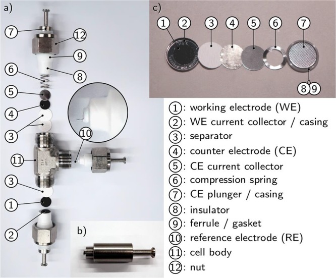
(a) Exploded view of a three-electrode Swagelok cell; (b) reference electrode plunger including a groove to attach a metallic wire or mesh; and (c) exploded view of a coin cell in half cell configuration versus lithium.
Following a somewhat similar approach the two and three-electrode “Conflat” cells were recently introduced using standard ultrahigh vacuum fittings14 instead of gas tubing fittings (as in Swagelok cells). Operating temperatures as high as 200 °C are reported for these cells with an insulator and gasket made of PTFE.
Coin cells represent another widely employed cell configuration to test active materials for battery applications. The assembly of a full Li-ion coin cell with a thin separator and electrodes of equal diameter, aiming at improved cell performance and cycle life, is a very delicate task.15 Fortunately, it is simplified in the framework of testing active materials only, in which a thick separator and larger counter electrode than working electrode can be employed, though a minimal care should be taken in the alignment to ensure that all of the WE is faced by the CE. An unassembled coin cell is shown in Figure 1c). The inner parts are simply a current collector and a spring to maintain pressure on the electrodes stack. A polypropylene gasket ensures both functions of electrical insulation and air tightness; the sealing is performed by a specific crimping machine, which implies the need for a dedicated space in a glovebox. The tight sealing of coin cells makes them a setup of choice for long-term cycling at lab scale.
Examples of coin cells in three-electrode configuration can be found in refs (16−20). In the simplest cases, the supplementary RE consists of a thin wire passed between the gasket and the casing.17,19,20 The assembly of such cells is very tricky19 as breaking of the reference wire or shortage will easily happen. The presence of the wire can affect the air-tightness of the cell, and consequently they commonly have to be kept in a glovebox17 or sealed with epoxy after crimping,19 which can hardly be expected to be as reliable as a standard coin cell in the long term. An alternative consists of modifying the cell’s hardware to integrate the RE,18 in which a more reliable sealing would be expected at the cost of an important work in the cell design and manufacturing.
After characterization of the materials, it is of high interest to investigate the performance of the most promising ones as constituents of an actual battery, i.e., in a “full cell” configuration. Coin cells are commonly used for this purpose, in which the lack of an RE is usually a secondary issue. Pouch cells are much closer to commercial cells and are therefore preferred for systematic studies at the cell level.21 They have the counterpart of being more demanding in terms of amount of active material and equipment to prepare homogeneous electrodes at larger scale and seal the cells. In the case of post-Li-ion technologies, the use of pouch cells for sodium-ion22,23 or magnesium–sulfur24 systems has been reported.
Several new cell designs have been reported mostly aiming at improving the quality of impedance spectroscopy measurements (see impedance section)25−27 or in order to facilitate in situ/in operando characterization tests.11 Each technique brings constraints to the design of an operando cell in terms of geometry, materials properties (such as transparency to certain wavelengths), or the positioning of actuators. Examples of cells developed for in operando techniques include X-ray diffraction or absorption,28,29 infrared spectroscopy,30 UV–visible spectroscopy,31 mass spectrometry,32 or NMR.33 The democratization of 3D printers broadens the possibilities to build custom cells, mostly using polyolefins.
Cells dedicated to the electrochemical testing of materials for battery applications are also commercialized by a few companies and were used in some studies.27,31,34,35 Two- or three-electrode configurations are commonly available. Some of these cells were designed mostly for Li systems and their constituting materials might not be compatible with electrolytes based on alternative cations, but products made of the most resistant materials and ready to work with metallic or carbon quasi-reference electrodes are also offered.
Current Collectors
Reactions at the current collectors may limit the operating window of the cell. In current-controlled techniques, such reactions can lead to endless and noisy voltage plateaus.
At the cathode side, corrosion of the cell’s hardware may occur, which may depend on the nature of the electrolyte salt. This can be exemplified by the corrosion of aluminum initiated in TFSI-based electrolytes, which can be prevented by adding LiPF6 in the electrolyte to form an AlF3-rich passivation layer.36 However, it is not always desirable to alter the composition of the electrolyte, and not all PF6– or BF4– based salts are easily available and/or dried. For instance, Mg(BF4)2, Mg(PF6)2, and Ca(PF6)2 are not commercially available, Ca(PF6)2 is not stable,37 and only hydrated Ca(BF4)2 can be purchased and needs extensive drying procedures. Overall, only TFSI-based Mg and Ca salts are available dry and are commonly used. In such cases, the current collector material used can significantly affect the voltage window, as shown in Figure 2, which informs on the anodic stability limit with Al, AISI 316 stainless steel, or Ni80Cr20 alloy used as the working electrode in 0.3 M Ca(TFSI)2 in ethylene carbonate (EC):propylene carbonate (PC) electrolyte. Among the three materials tested in Figure 2, AISI 316 offers the highest anodic stability. While stainless steel might bring a weight penalty in practical application because of its density nearly as high as that of copper, this is not a problem at the stage of materials testing.
Figure 2.
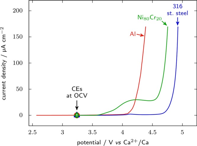
Linear voltammetry sweep recorded on 1000 series Al, AISI 316 stainless steel, or Ni80Cr80 alloy at 0.1 mV s–1 in 0.3 M Ca(TFSI)2 in EC:PC at room temperature.
Commercial coin cell casings are often made of AISI 304 stainless steel, which has significantly lower resistance to corrosion than 316.38 With such casings, an Al deposit39 or a disk of Al foil40 (or 316 stainless steel) at the working electrode side can be used to increase the maximum cell voltage. It needs to fully cover the inner surface of the can to ensure that the gasket takes place on the foil or Al deposit and no part of the WE casing is accessible to the electrolyte. While most of corrosion issues are due to the electrolyte, active material can also be problematic. For instance, elemental sulfur and polysulfides can lead to significant corrosion of common current collector such as stainless steel and copper. Such corrosion potentially has an impact on the overall electrochemical response through cycling of copper sulfide species.49
At the anode side, the voltage window may be limited by the alloying of the current collector with the cation in solution. The typical example is the electrochemical formation of an alloy of Li and Al at ∼0.3 V vs Li+/Li,41 which is the reason for the use of copper current collectors in commercial Li-ion cells. A similar issue can occur in Na cells when low purity Al plungers are used, which can contain traces of Pb that can alloy with Na.42 Calcium and magnesium can form thermodynamically stable alloys with aluminum or copper as well;43 however, several groups use these metals as current collectors at low voltages without reporting issues of electrochemical alloying,44−48 suggesting that their alloying with divalent cations might be kinetically limited. Since electrochemical quartz crystal microbalance and rotating disc electrodes commonly use Au and Pt as working electrodes, it is worth mentioning that Na, K, Mg, and Ca can all alloy with Au and at least Na and Ca can alloy with Pt, whereas we could not find data for the Mg–Pt and K–Pt systems. A systematic investigation on the possibility to form Ca or Mg based alloys with conventional metal substrates used in battery testing (Cu, Al, Pt, Au, or SS) is still lacking.
Insulator
As mentioned above, an insulator material is required in order to prevent direct contact between the current collectors of the different electrodes, i.e., cell short circuit. It is only required for compact cell designs such as Swagelok or coin cells but not for the beaker type, as the electrolyte acts as the electronically insulating material between the electrodes. Li cells commonly use boPET (Mylar) foil as insulator, which displays good chemical compatibility with organic electrolytes commonly used in batteries. However, certain electrolyte decomposition products have been proposed to attack Mylar. This is the case of sodium cells with glyme-based electrolytes producing both highly reactive radicals and strongly basic alkoxides.50 As Mylar is not resistant to highly alkaline media, polyether ether ketone (PEEK) is preferred in such applications.51
As it is easily machined, PEEK is used to fabricate complete cells bodies apart from only insulating the electrodes.26,52 It is inert toward metallic lithium as well as toward Li-ion electrolytes53 and can operate at temperatures up to ∼300 °C.
PTFE is also widely employed, especially since it is available in the form of tapes that can be used to cover the plungers. However, it is not suitable for low potentials as it gets defluorinated in contact with alkali metals, forming carbon. After a long exposure, the carbon formed may even produce short circuits.14,54,55 In contact with sodium metal, the reaction is highly dependent on the solvent used: no evidence of PTFE decomposition is observed in carbonates, whereas it is important with diglyme.40 PTFE decomposition has also been proposed to be at the origin of capacity loss with graphite anodes when used as binder.56 This reaction seems to be less problematic in the case of Ca and Mg cells as no evidence of such decomposition has been reported so far.
Polyamide (Nylon) had been extensively used as sealing material for Ni–Cd and Ni–MH batteries (both cylindrical and coin cells) until shown to be incompatible with the alkaline media.57 Nylon can be machined to form specific cell designs.58 No big issues are reported regarding its stability against lithium anodes, but the temperature range is limited: the melting point is 220 °C but mechanical strength starts to get lost at temperatures as low as 50 °C. For this reason, Nylon ferrules and gaskets should be reserved to tests at room temperature or slightly above.
Other more exotic polymers can be used as insulators for specific setup requirements. For instance, polyimide (Kapton) can be used for high temperature applications, being stable up to 400 °C. It can be found in several formats: Kapton HN is a plastic film of different thicknesses, and Kapton FN is an adhesive tape, in which the Kapton film is covered by a fluorocarbon resin to provide adhesion characteristics. Note, however, that the fluorocarbon resin is similar to PTFE and PVDF and its instability in lithium batteries at low potential has been reported.14
Polyolefins (polypropylene, high-density polyethylene, etc.) form a very versatile family of polymers with higher stability at low potentials than the PTFE. However, they might be less resistant to dissolution and solvent uptake and could present low thermal stability depending on the polymer.59
Overall, in our research on Na, Mg, and Ca we found the use of PTFE very convenient in terms of shape (available in the form of tapes) and temperature stability, some tests requiring temperatures up to 100 °C (for Ca plating for instance). However, alternatives such as PEEK must be used in glyme based electrolytes.
Separator
While insulating material is necessary in order to prevent short circuit by direct contact between the different current collectors and the metallic core of the cell (if Swagelok cells are being used), an electronic insulation is also needed between the WE and the CE. This is the role of the separator, usually consisting of a porous and electronically insulating structure which can be wet by the electrolyte, thus ensuring ionic transport through it. A large number of separators have been developed and are commercially available depending on the battery technology under test.60,61 However, at laboratory research scale there are mainly two types used: polyolefin membranes (e.g., commercial Celgard separators) and glass fiber.
Polyolefins, being thin (<30 μm) and highly chemically resistant, are extensively used in both laboratory and commercial cells. The preferred composition of a polyolefin separator is a three-layered membrane composed of polypropylene/polyethylene/polypropylene (PP/PE/PP). The outer PP layers provide high resistance to oxidation and reduction at the electrodes while the inner PE layer works as a thermal fuse. When the temperature of the cell goes above 130 °C the PE melts closing the pores of the separator and avoiding further heating and eventual thermal runaway. Polyolefins are very resistant to highly caustic or acidic media and have good compatibility with many organic solvents,62 but wettability issues are common with viscous electrolyte such as PC-based ones.
In laboratory cells, where the thickness is not as crucial, glass fiber is more extensively used. Based on borosilicate glass, it presents excellent chemical and thermal stability. An important exception is the susceptibility of borosilicate glass toward the attack by HF. In lithium-ion cells, HF is a known hydrolysis product of fluorinated anions, such as PF6– and BF4–. Therefore, special attention must be devoted when traces of water are present in the electrolyte which might generate HF which attacks the separator forming more water and soluble boron compounds.63
We have found that the commercial glass fiber separators can also release corrosive products in the electrolyte solution. This is illustrated by Figure 3 which reports cyclic voltammograms of 316 stainless steel WE and 0.1 M Ca(TFSI)2 in PC electrolyte after different pretreatments of the WE or separators. In Figure 3a), without specific treatment of either WE or separators, an oxidation peak is observed around 3.1 V vs Ca2+/Ca, that grows for the first 55 cycles to reach a maximum of more than 200 μA cm–2 and then vanishes. It is associated with important reduction current below 2.6 V and oxidation current above 3.5 V vs Ca2+/Ca, all three features following the same trend of reaching a maximum after 55 cycles and then decreasing. This response appears related to the passivation of the stainless steel electrode, as confirmed by Figure 3b for which the WE was passivated in 20% nitric acid64 prior to cell assembly. In this case the same features can be identified on the voltammograms, but their magnitude is decreased by an order of magnitude, which indicates that the associated process is inhibited by the pretreatment in nitric acid. However, the elimination of these parasitic electrochemical features is even more efficient by simply soaking the separator in the electrolyte at 100 °C and then rinsing with DMC (in Figure 3c). Indeed, in this case no parasitic process can be seen, even without pretreatment of the working electrode in nitric acid. Simple rinsing of the separators with DMC at room temperature also leads to the disappearance of these parasitic redox features (Figure 3d), yet the baseline of the cyclic voltammograms appears broader than in (c). These results point at the separators as the origin of the peaks observed in Figure 3a through the release of some corrosive product, the exact nature of which is not determined yet.
Figure 3.
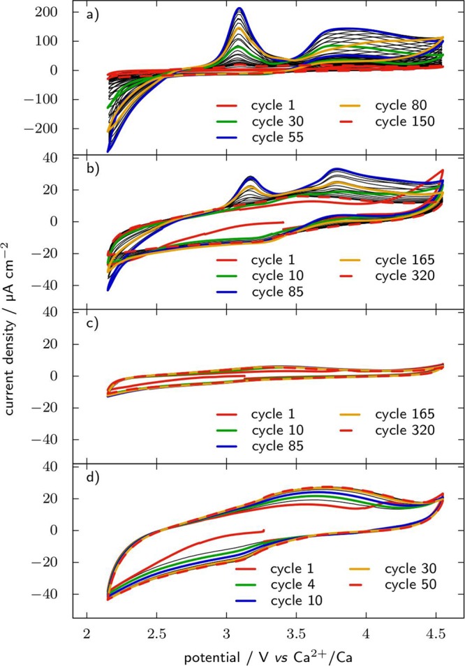
Cyclic voltammograms recorded at 20 mV s–1 on a 316 stainless steel plunger as working electrode in 0.1 M Ca(TFSI)2 in PC at room temperature with an activated carbon counter electrode. (a) Glass fiber separator and polished working electrode are used without further treatment; (b) the working electrode was passivated for 1 h in 20% HNO3 after polishing, and the separators are used without treatment; (c) the separators were soaked for 5 days in the electrolyte at 100 °C and then rinsed with DMC before use, and the working electrode is as polished; and (d) the separators were rinsed with DMC only, and the working electrode is as polished
Counter and Reference Electrodes for Monovalent Systems (Na and K)
Beginning with the CE, its basic requirements are to reversibly store charge (not involving electrolyte contamination) and to have sufficient capacity to sustain the current density arising from the redox processes occurring at the WE. For a given cation the counter electrode having the highest theoretical gravimetric capacity is the corresponding metal, but its use is not always appropriate.
With lithium metal electrode an electronically insulating and ion-conducting surface layer forms in contact with the electrolyte: the solid electrolyte interphase (SEI).65 This interphase will undergo breakdown and repair cycles during charge and discharge of the cell.66 The working of this metal electrode requires desolvation of the cation at the SEI/electrolyte interface, mass transport through the SEI, and charge transfer at its interface with the metal. The voltage of the lithium electrode is reproducible only at current densities lower than 1 mA cm–2,67 which is enough to test most active materials in two-electrode cells (typically requiring few tens to hundreds of μA). For higher current densities, a third electrode will be needed as a reference versus which the potential can be reliably measured. In other battery chemistries, however, the operation of the metal electrode is not as trivial.
In the case of metallic sodium, in most electrolytes it works similarly by formation of a SEI, this SEI being more soluble in Na than in Li systems.7,68 Using conventional alkylcarbonate based electrolyte, continuous electrolyte decomposition will prevent from running any long-term cycling and leads to the production of electroactive species in solution.8 Though significantly decreased, continuous electrolyte decomposition is still observed with FEC additive. Upon plating, Na metal has a higher tendency than Li to grow dendrites, which may result in cell failure due to internal shortage.16 Upon stripping, voltage steps experienced by the Na CE can also misleadingly be attributed to the working electrode in two-electrode configuration.6 Altogether, given the extra polarization of the sodium electrode,8 its higher impedance,7 leading to unreliable potential, a three-electrode configuration is needed in most Na cells to avoid biased conclusions. As an example, low voltage anodes such as hard carbons can reach the lower cutoff voltage upon reduction before the full capacity can be accessed due to the polarization associated with the CE in a two-electrode configuration.
Given that the SEI stability is more problematic with Na than with Li and that the solubility of alkali salts in water increases when moving from Li to Na to K,69 significant issues associated with the use of K metal CE could also be expected. K cells are generally assembled in two-electrode configuration vs K metal, similarly to most Li half cells. However, in this configuration, part of the capacity lost after 120 cycles can be recovered by changing electrolyte and K electrode,70 which shows that it does not work as an ideal CE. Soluble products of the electrolyte decomposition on K metal can also diffuse toward the WE, potentially affecting the representativeness of the performance of the material tested.71 FEC is occasionally used in K cells, though it is not clearly stated whether the purpose is to limit electrolyte decomposition at the CE or build a better SEI on the WE. However, when comparing Li, Na, and K metal anodes in contact with perchlorate salts in PC solutions, a substantial amount of soluble decomposition products was only detected in Na cells suggesting a better stability of Li and K interfaces.68,72 Overall, solubility issues of passivation layers in K cells are not fully understood and a systematic investigation is needed.
Moving to the RE, it should ideally be “reversible, reproducible, constant in time and easy to prepare. Generally, the reference electrode is reversible to one of the ions in the solution to avoid liquid junctions.”73 Unlike aqueous systems where references are commonly reversible to an anion, in a lithium cell, voltage is determined by the activity of Li+ at the vicinity of the reference, which can safely be considered as constant. Electrodes reversible to the cation can be divided in three categories: the metal itself, metallic alloys, and insertion materials. Though these different types of REs work very well with Li, their applicability to other cation-based systems is not straightforward.
As discussed previously, unstable Na metal/electrolyte interfaces and partial dissolution of the SEI can affect the measure in alkylcarbonate electrolytes.9,74 Also, in the case of K cells, the addition of FEC tends to improve the stability of the metal/electrolyte interface in alkylcarbonate electrolytes.75 In ether solvents (such as glymes) a stable operation of a K metal electrode depends greatly on the salt used, the KPF6 being the worst performing—in opposition to the case of Li.76 Altogether, it is clear that not all electrolyte systems commonly employed for lithium cells are directly transferable to Na or K and further research into SEI formation on metal electrodes is needed in these cases. It is highly recommended to evaluate the stability of the metallic electrode when used as CE and/or RE.
Aside from metal electrodes, metallic alloys and insertion materials can be used as REs reversible to the cation in solution. For such systems to be suitable, they need to be biphasic and therefore display a constant voltage for a wide range of compositions. In Li-ion cells, several alloys such as LixSn,17 LixAu,77 or LixBi78 as well as insertion materials such as lithium titanate and lithium iron phosphate27,67 have been used. These REs are usually prepared in situ, possibly using composite electrodes. Alloys present the advantage that metallic wire can be used (Sn, Au, ...), the alloy being formed at its surface, thus miniaturization, easy handling, and precise placement of the reference are possible. The counterpart is that dealloying can occur with time and the potential of such RE eventually drifts.79 Most of the insertion type electrodes, on the other hand, operate within the stability window of most electrolytes resulting in a passivation free surface and improved potential stability. While alloys and insertion type references would be highly advantageous in Na and K cells and there is a large amount of potential material candidates, there is, to the best of our knowledge, no report on their use in Na and K half cells.
Additional to the nature of the reference electrode, its placement in the cell is also vital. REs made of soft metals such as Li or Na can be implemented in Swagelok cells by replacing the wire in Figure 1a by a piece of mesh onto which the metal is pressed or using a specifically designed plunger.77 The simplest approach consists in using a second metal disk as the RE but may be poorly reliable. Indeed, to avoid the blocking of cation conduction through the cell the RE disk has to be located outside of the WE-CE stack, which can lead to voltage discrepancies between RE and CE of the same nature. For instance, in a Na cell with metal CE and RE the difference is commonly as high as 15 mV at open circuit when the RE is a 10 mm disk located 7 mm outside of the WE–CE stack (typical for a three-electrode Swagelok cell), whereas it is less than 2 mV when the RE is a 3 mm strip at the vicinity of the WE.
Counter and Reference Electrodes for Divalent Systems (Ca and Mg)
Regarding divalent cations, Ca and Mg anodes work only in limited combinations of temperature, salt, and solvent. To date, the metallic Mg anode can only work in ether-based electrolyte solutions for which the electrochemical stability window above 3 V remains a challenge.3,80−82 Care should thus be taken when high voltage cathodes are investigated, as currently available electrolytes will most likely not allow for both efficient Mg plating/stripping and sufficient anodic stability. Unlike for Li metal, formation of the passive film on Mg metal tends to block divalent cation migration, preventing plating and stripping.83 Thus, any presence of oxygen, water, or other impurities in the electrolyte (even at the ppm level) can lead to inactive passivating films. Several methods have been employed in order to overcome this issue, including the addition of Mg–chloride salts,84 the use of magnesium powder for which an acceptable degree of Mg free surface could be maintained,49 and the use of a so-called “conditioning” process,83,85 which consists of performing several plating and stripping cycles until the stationary electrochemical response is obtained. Therefore, the use of the Mg metal electrode is far from being obvious, and if the nature of its interface with the electrolyte is not carefully considered during battery material testing it can lead to discarding promising electrode or electrolyte materials.
Moving to calcium, the use of the metal anode is even more challenging than for Mg. Indeed, this technology is still in its infancy and plating/stripping has only been demonstrated in very limited conditions: above 75 °C in carbonate based solvents and Ca(BF4)2 salt86,87 or at room temperature with Ca(BH4)2 salt in THF, thus with limited anodic stability.88,89 Outside of these specific combinations of salt, solvents, and temperature, Ca metal CE cannot be used in the half cell configuration.
The most obvious and versatile alternative to a metal (Na, K, Ca, or Mg) CE is a capacitive electrode such as activated carbon (AC), which is regularly used to test active materials for batteries based on Ca or Mg.90−95 With such materials, ions are stored electrostatically on the carbon’s wide specific surface area. This mechanism, which does not involve charge transfer, brings high reversibility and works with a large variety of ions. It takes place in the voltage stability window of most electrolytes; hence, no passivation layer is formed which could affect mass transport. The counterpart is a relatively low specific capacity which requires careful sizing of the CE as a function of expected capacity of the WE. For example, for a 1.2 mA h WE which corresponds to 4.3 mg of active material with a specific capacity of 280 mA h g–1, at least 48 mg of a carbon having a capacity of 25 mA h g–1 are required. Such heavy counter electrodes can be easily obtained by piling several layers of self-standing electrode, either a bond with PTFE or in the form of cloth.
Using AC as the CE, care should also be taken as the cell will evolve differently whether the cation is initially present in the WE active material or not. In the first configuration, an example of which could be Ca3Co2O6,96 the experiment starts by oxidizing the WE to release cations in solution. At the CE, cations will be stored at the surface of the carbon and the cell is a “rocking-chair” system, which is schematized in Figure 4a. In the second configuration, as is the case with a material such as TiS2, the experiment starts by a reduction at the working electrode, which will consume cations from the electrolyte. In order to maintain electroneutrality of the solution, anions will be stored at the CE, which overall leads to gradual dilution of the electrolyte (Figure 4b). This effect is usually negligible but can become significant in extreme cases and have a significant impact on the ionic conductivity. For example, the same 1.2 mA h electrode as above in 600 μL of 0.1 M solution of divalent cation as electrolyte will require 30% of the total quantity of cations in the electrolyte for a full reduction. In such cases, precharging of the CE might be necessary. Precharging of the carbon electrode can be done by charging a two electrode carbon/carbon cell at the required capacity, and then recovering the negative and rinsing it with the electrolyte. During the precharging step, it is recommended to use a heavier (1.5–2×) positive electrode to prevent electrolyte decomposition at that electrode. With this procedure the AC electrode becomes a source of cations as for metal CE and, if the AC is carefully oversized, a rocking chair is achieved and no electrolyte dilution takes place (Figure 4c). Precharging the CE can also be a way to increase its available capacity and prevent it from reaching the anodic stability limit of the electrolyte, especially when the temperature has to be increased. Because the potential of the carbon electrode varies with the capacity, the use of an RE is mandatory. As a benchmark for the properties of a standard AC (YP17, Kuraray) when used as CE in a divalent cation based system, the capacity and rate capability of a 14.2 mg carbon electrode (with 5 wt % PTFE binder) and cycled in 0.1 M Ca(TFSI)2 in PC electrolyte are shown in Figure 5. For current density below 20 mA·g–1, a specific capacity of about 25 mAh·g–1 is obtained. As mentioned before, since most active materials are tested with current density below 1 mA·g–1 (especially true for divalent cation systems with low power performances), the value of 25 mA h g–1 can safely be considered for this carbon. Finally, it is advised to carefully wet the AC electrode with the electrolyte before cell assembly when working with high viscosity solutions. Indeed, since the capacity of the electrode is directly proportional to the surface in contact with the electrolyte, the wettability issue will result in capacity decrease. The electrode can be placed in the electrolyte overnight and/or placed in the electrolyte and under vacuum in order to remove as many trapped gas bubbles as possible before cell assembly.
Figure 4.
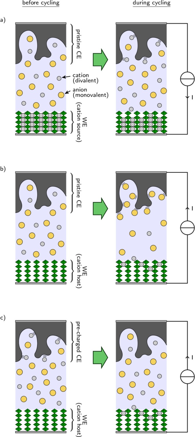
Schemes of cells using carbonaceous counter electrodes, after assembly and during cycling. In (a) and (b), a pristine CE is used in combination with a WE that is either (a) a cation source or (b) a cation host; (c) a cation host-type WE is combined with a previously charged CE.
Figure 5.
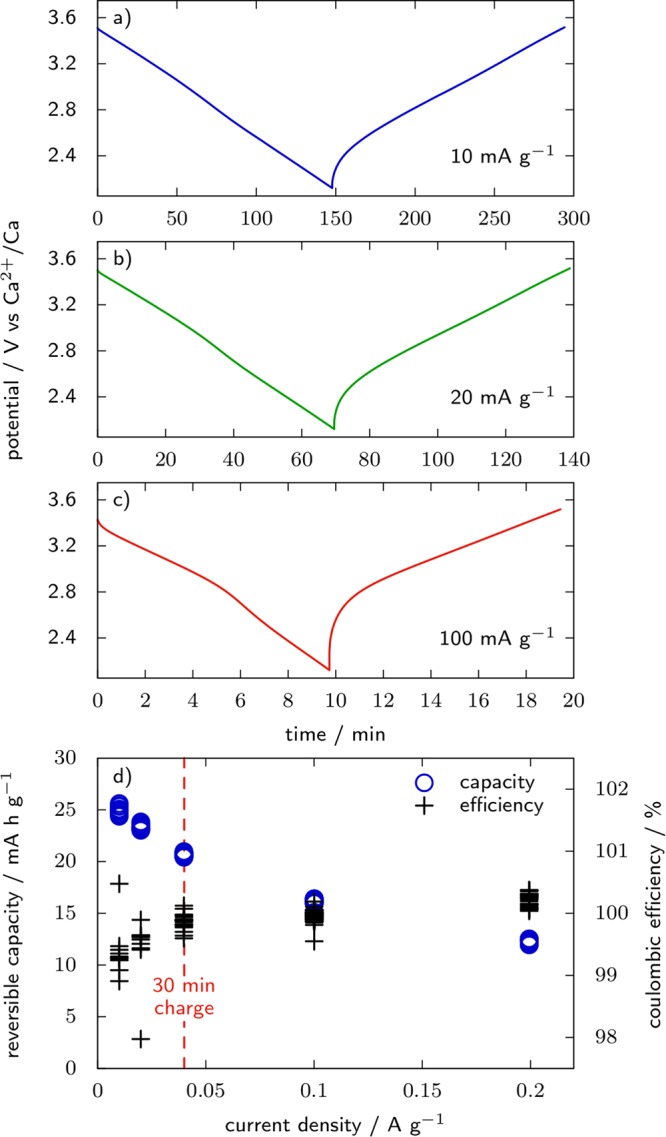
(a–c) Galvanostatic charge and discharge profiles of Ca2+ in YP17 activated carbon from rest potential down to 2.1 V vs Ca2+/Ca (−1.3 V vs the Ag/Ag2S RE employed) at room temperature in 0.1 M Ca(TFSI)2 in PC. The current densities are 10, 20, and 100 mA g–1 in (a), (b), and (c), respectively. (d) Reversible capacity and Coulombic efficiency as a function of the current density. The CE is an overcapacitive (2.5× the mass of WE) YP17 electrode.
With respect to reference electrodes, significant potential shifts for Ca and Mg pseudo-REs have already been reported by a few groups,9,86,97 with amplitudes depending on the experimental conditions. The general trend being that ether-based electrolytes lead to relatively small potential shift, if any (below few hundreds of mV), while shift as large as 1 V can be measured in alkylcarbonate solutions. This suggests a significant influence of the nature of the passivation layer formed on the metal electrode on its potential. In the absence of formation of a passivation layer, the potential of the metal RE is most likely influenced by its initial surface chemistry such as for quasi-reference electrodes (QREs, thus, at least partly, depend on the electrolyte water content).
As for Na and K, the use of an alloy or insertion type RE in Mg and Ca cells has not yet been reported. However, electrochemical alloying with Mg was demonstrated with micrometric In,45 Bi,44 or sputtered Pb,98 which display characteristic voltage plateaus for a wide composition range. This suggests these alloys might be suitable as references in Mg cells, provided they do not passivate in the electrolyte used (plateaus are typically observed below 0.3 V vs Mg2+/Mg).
Conventional Electrochemical Techniques for Post-Li Battery Testing
Schemes of a potentiostat connected to a two or three-electrode cell are represented in Figure 6a,b, respectively. Two cables are connected to the WE, one to the CE, and one to the RE. A fifth cable might be present allowing the voltage of the CE (not represented) to be recorded. The current I is applied between WE and CE, and the voltage V is measured between WE and RE: The current i flowing through the RE remains negligible thanks to the high input impedance of the potentiostat (>10 GΩ), and thus in the three-electrode configuration the processes occurring at RE have no contribution to the voltage V (WE potential vs RE plus the ohmic drop, discussed below).
Figure 6.
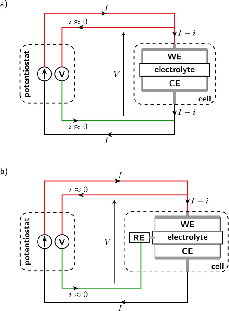
Scheme of a potentiostat connected to a two-electrode cell (a) or a three-electrode cell (b).
Cyclic voltammetry (voltage controlled, CV) and galvanostatic cycling (current controlled, GC) are the two base techniques employed to test active materials. Details of the cyclic voltammetry experiment and analysis can be found in ref (99). GC is usually preferred over CV for battery tests because they can display important capacities over a narrow voltage window, thus saving time on less important potential regions, and enable for a more complete reactivity of the material. The capacity and Coulombic efficiency are also determined with better precision using galvanostatic cycling. In most cases, both CV and GC techniques are more reliable when performed in a three-electrode cell configuration in which the potential of the RE will remain stable during cycling. This is true for Li cells and often mandatory for Na, K, Mg, and Ca systems for which the metal RE is not reliable, especially if also used as the CE. An additional parameter that should be considered is the uncompensated ohmic drop (or IR drop) in the electrolyte that will always arise between the WE and the RE. Three parameters dictate the extent of this IR drop: the electrolyte ionic conductivity, the distance between the WE and the RE, and the current flowing through the WE (see Table 1 for estimation of IR drop values in various conditions). While the first two parameters are fixed for a given electrochemical setup, current density varies during a CV experiment and is fixed during a GC test. Therefore, while the IR drop will only shift the whole GC curve (to lower or higher potential values upon reduction or oxidation of the WE, respectively), it can significantly affect the CV curve shape. Due to the high ionic conductivity of the Li based electrolyte, the IR drop usually tends to be negligible and so is expected for Na and K systems which commonly present even better salt dissociation and mobility in solutions than for Li. However, Ca and Mg based electrolytes suffer from poor salt dissociation and mobility,9 which can result in a significant IR drop depending on the cell geometry (Table 1). A high uncompensated IR drop will lead to misinterpretations of electrochemical processes.100 Careful RE positioning in Ca and Mg cells is thus even more crucial than for monovalent systems in order to record reliable electrochemical data.
Table 1. Uncompensated Ohmic Drops in the Electrolyte for Various Working to Counter Electrode Distances, Electrolyte Conductivities, and Current Densities.
| cell length | 25 μm | 450 μm | 5 mm | ||||||
| (WE to RE) | (polyolefin separator) | (glass fiber separator) | (beaker cell) | ||||||
| conductivity, mS cm–1 | 1 | 5 | 10 | 1 | 5 | 10 | 1 | 5 | 10 |
| areal resistance, Ω cm2 | 2.5 | 0.5 | 0.25 | 45 | 9 | 4.5 | 500 | 100 | 50 |
| ohmic drop at | |||||||||
| 10 μA cm–2 | 25 μV | 5 μV | 2.5 μV | 450 μV | 90 μV | 45 μV | 5 mV | 1 mV | 500 μV |
| 220 μA cm–2 | 550 μV | 110 μV | 55 μV | 9.9 mV | 1.98 mV | 990 μV | 110 mV | 22 mV | 11 mV |
| 5 mA cm–2 | 12.5 mV | 2.5 mV | 1.25 mV | 225 mV | 45 mV | 22.5 mV | 2.5 V | 500 mV | 250 mV |
While CV and GC consist of varying linearly the potential or the total capacity passed through the sample, the potentiostatic intermittent titration technique (PITT)101 and galvanostatic intermittent titration technique (GITT)102 consist of stepwise variations of these parameters. For PITT the voltage varies by steps of a few mV and current decrease is monitored for a given time or until it reaches a given value, and then the voltage is incremented. Similarly, GITT involves increments of capacity in the form of galvanostatic pulses, followed by relaxation periods.
PITT and GITT serve two main purposes: obtaining the potential as a function of composition in conditions close to equilibrium (the titration curve) and estimating the diffusion coefficient of the cation inside the active material. Using reliable RE, the former is straightforward: potential and total capacity are taken right before every voltage step or current pulse to plot the titration curve. The latter relies on the analysis of the transient profiles, with underlying assumptions regarding the geometry of the diffusion medium and whether multiple phases or a solid solution are involved.
Originally, the equations permitting extraction of diffusion coefficients from the GITT and PITT techniques were derived for the case of 1D diffusion through a thin film or a pellet.102,103 Diffusion through a single solid solution is considered that may have a very narrow composition range, and infinitely fast reaction at the interface with the electrolyte is considered, in such a way that the process is purely diffusion controlled. Battery electrodes usually consist of a porous composite of the active material, a conductive additive, and a binder, which is impregnated with the electrolyte. In this case, the diffusion through the active material can hardly be considered as a 1D axisymmetric and may be closer to 1D radial diffusion in the case of spherical particles with a narrow size distribution.104 The concentration profiles in the active material and, therefore, the current (for GITT) or voltage (for PITT) response, will also be altered if the reaction at the interface is not infinitely fast. In the case of divalent cations that have high solvation energies, desolvation at the interface might become the rate-determining step, in which case using equations derived in the case of an infinitely fast surface reaction will not be valid. For the PITT technique, the influence of the rate of surface reactions was analyzed in refs (105 and 106) in the case of an electrode slab and spherical particles, respectively.
Using intermittent titration techniques to estimate a diffusion coefficient may require dedicated electrode formulation and cell constituents, especially regarding the separator, which should preferably be a thin polymeric membrane rather than a thick glass fiber layer.107 The estimation of diffusion coefficients in two-electrode cells implies the assumption that the cell voltage only reflects processes at the WE. This requires low polarization and fast relaxation at the CE side. This would hardly be the case for Ca and Mg metal.
Electrochemical impedance spectroscopy (EIS) is another widely employed technique to investigate battery materials. It consists of applying a sinusoidal voltage or current perturbation to the cell and varying its frequency. The perturbation needs to be sufficiently small for the system to give a linear response that will be a sinusoidal wave at the same frequency with a certain phase shift. Because of this phase shift the ratio between voltage and current is a complex impedance that can be reported as a Bode or a Nyquist plot. Impedance spectroscopy can bring information regarding the different processes occurring in the electrochemical cell, such as mass transfer in the electrolyte or through an SEI, charge transfer, or diffusion, since they will contribute more or less significantly to the conduction of electrical current depending on its frequency.
The impedance technique relies on the assumption that the response of the system studied is linear, causal, stable, and finite, which implies that the data should verify Kramers and Kronig transforms. The easiest way to check the linearity and stability of the response is to repeat the measurement with a different amplitude of the perturbation and verify that the impedance spectrum is unchanged.108 Fitting the data with a series of Voigt elements, which complies with Kramers and Kronig relations, is a relatively easy way to identify the frequency range over which the data is consistent.109 Modern electrochemical software may include a Kramers–Kronig module to do this test. Other methods to perform this verification are reviewed in ref (108).
Potentiostatic EIS (PEIS) may be considered more convenient because potentiostats usually offer various current ranges and can automatically switch to the most adequate to perform the measurement, whereas galvanostatic EIS (GEIS) requires some idea of the order of magnitude of the impedance to select the appropriate current. Apart from extreme cases of cells with very high (where PEIS should be preferred) or very low impedance (GEIS preferred),110 both techniques should be equivalent.77 Below we discuss the specificities of impedance measurements in two or three-electrode cells.
In the two-electrode configuration, symmetrical cells (same electrodes and state of charge) can be used in a measure that leads to twice the mean impedance of one of the electrodes in series with the resistance of the electrolyte.111,112 This procedure can produce reliable impedance spectra but requires twice the amount of active material and cell disassembly and reassembly in symmetrical cells that makes impedance study as a function of time or state of charge a laborious task. The two-electrode configuration can be used in order to evaluate the overall impedance of full cells during aging in conditions close to application. However, for materials testing in cells that are not symmetrical, there is hardly a way to discriminate the contribution of the WE from that of the CE. This is shown in Figure 7 in which the impedance of a symmetrical hard C/hard C cell is compared with that of a hard C/Ca cell, with 0.1 M Ca(TFSI)2 in PC as the electrolyte. For the hard C/Ca cell, a huge loop is observed that has an amplitude of ∼100 kΩ cm2. This corresponds to the contribution of the Ca electrode since the impedance of the hard C electrode is half that of the hard C/hard C cell (<30 kΩ cm2). For cells that are not symmetrical, it is therefore mandatory to use a three-electrode configuration in order to remove the contribution of the CE.
Figure 7.
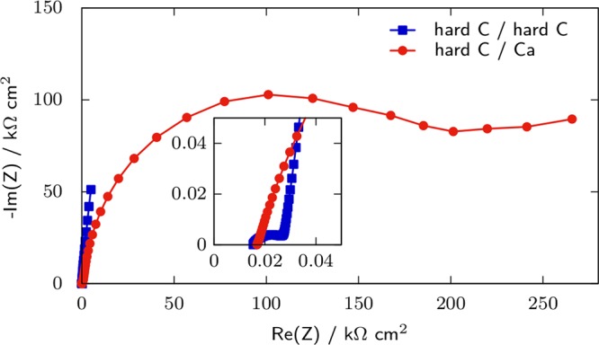
Impedance of symmetric hard C/hard C and hard C/Ca cells at rest potential with 0.1 M Ca(TFSI)2 in PC as electrolyte in a two-electrode configuration, at room temperature. The frequency range is 1 MHz down to 10 mHz, with a 20 mV single sine perturbation.
In three-electrode configuration, artifact loops can easily appear that can originate from geometrical asymmetry (such as a difference in size or misalignment between WE and CE) or electrochemical asymmetry (WE and CE of different natures).26,27,34,113 Comparing the impedance obtained in a three-electrode configuration with that of a symmetrical cell is an efficient way to check the reliability of the experimental setup. To avoid issues with electrochemical asymmetry, the impedance of the CE should be at most equivalent to that of the WE, since the impedance spectrum displaying the lowest magnitude of the two electrodes will be distorted.52 As discussed above, Ca and Mg metals usually display very high impedance (>100s of kΩ cm2), even in conditions where plating and stripping are actually possible,9 and thus artifact loops are likely to appear in impedance spectra when Ca or Mg CEs are used. Regarding geometrical effects, several cells were designed with higher symmetry than the standard configuration having the RE placed at the side. While these cells were developed for Li systems, their design can inspire post-Li tests. Most of them use concentric RE and CE, with the CE punched at its center and the reference placed in the middle.18,25,26,52 To avoid distortion of the impedance spectra, it is recommended that the WE presents the same hole as the CE,18 which can be used to place a second reference element.26 Alternatively, the insertion of a mesh coated with an intercalation material (LTO) placed between the WE and the CE was proposed.27 Accordingly, such configuration limits the impact of both geometrical and electrochemical asymmetries. A ring shaped electrode can serve the same purpose, as seen in Figure 8. It reports the impedance at OCV of a PTFE-bond YP17 (activated carbon) electrode in a three-electrode configuration with Ag/Ag2S QRE either in the form of a wire located at the edge of the WE–CE stack or a ring placed between the two electrodes. With the tip-shaped electrode, an artifact loop is observed in the Nyquist diagram, which is partly located in the first quadrant of the complex plane. On the opposite, with the ring-shaped electrode the spectrum remains in the second quadrant. It consists of a semicircular loop (attributable to charge transfer at the current collector/composite active material interface) followed by a 45° slope (diffusion of ions in the porosity of the carbon) and then a quasi-vertical line (capacitive behavior), which is the expected shape for the impedance of an activated carbon electrode in an organic electrolyte without optimization of the interface between the current collector and active material.34,114
Figure 8.
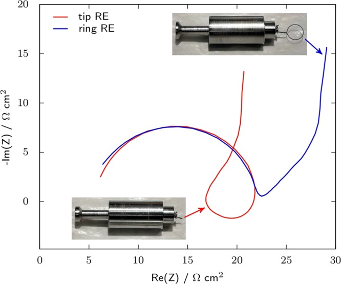
Impedance of YP17 activated carbon in EC:DMC–1 M LiTFSI at OCV with a YP17 CE and a Ag/Ag2S QRE either in the form of a tip located at the edge of the WE and CE or in the form of a ring placed between them. The frequency range is 10 kHz to 10 mHz, with a 10 mV single sine perturbation. The same set of WE and CE was used in both cases (10 mm diameter and 17.4 and 17.2 mg cm–2 of activated carbon, respectively).
While impedance techniques are very sensitive to cell asymmetry, they are less demanding in terms of potential stability for the WE. Since these measurements are usually shorter (typically a few minutes to 1 h) than other techniques such as galvanostatic cycling, the only requirement is that the voltage drift remains negligible with respect to the amplitude of the perturbation for the duration of the longest period (i.e., at the lowest frequency investigated).77 However, a high impedance of the RE (ZRE) can be detrimental if the ohmic drop ZRE × i (see Figure 6b) becomes significant with respect to the amplitude of the perturbation.115
Overall, for impedance measurements, Ca and Mg metal electrodes should not be used as the CE and/or RE in both two- and three-electrode configurations due to their usually high impedance which could lead to significant error or artifact loops and alternative CE and RE or symmetric configuration should be preferred. Na and K metal impedance is also rater high (at least in alkyl carbonate electrolytes7,75), and its impact on impedance measurements when used as the CE and/or RE should be carefully considered.
Versatile Electrochemical Setup for Post-Li Systems
Alternative RE and CE electrodes should be used in post-Li cells, especially for Mg and Ca systems. With respect to the RE, an easily implemented alternative to a metal electrode is a QRE, which consists of a piece of another metal such as Ag or Pt. QREs are commonly used in ionic liquids,116 where no reversible electrode with respect to either ion in the electrolyte is available. The Ag or Pt wire is directly immersed in the test solution or in a dedicated compartment separated by a glass frit. The latter configuration limits the influence of the reactions occurring at the WE and CE on the potential of the RE but requires the test to be run in a glovebox unless a specific cell is developed. Activated carbon (AC) QREs were also suggested as viable potential references since the high surface area of this material makes it less sensitive to impurities that could be generated during the operation of the cell.117,118 The main drawback of QREs is that their potential is governed by reactions that are not well-defined. As mentioned in ref (119), “the commonly used quasi-reference electrode (based on either silver or platinum wire) functions through the presence of various compounds (most likely oxides) on the metal surface. The exact identity of the ‘redox couple’ is never known with any certainty.” Consequently, the potential of a QRE cannot be evaluated theoretically and needs to be calibrated versus a known redox couple, which is commonly done by adding an electroactive specie in the solution after the measurement.120,121 This procedure relies on the assumption that the potential of the RE was steady for the whole duration of the experiment. For the test of active materials that usually last for tens of hours to several days, this can become a strong assumption. Ferrocene (Fc) and cobaltocene (Cc) are the most common electroactive species employed to calibrate the voltage of QREs. The standard potentials of Fc+/Fc and Cc+/Cc are 0.4 and −0.92 V with respect to the normal hydrogen electrode, respectively,122 and are assumed to be independent of the nature of the solvent. This assumption is due to the structure of the ions that are “univalent, large, symmetrical [···], with the charge deeply buried”, in such a way that their activity is the same as that of a neutral molecule with the same shape and independent of the solvent.123
Since the potential of the QRE such as silver wire is controlled by its surface chemistry, one way of stabilizing/fixing its potential is by controlling its surface chemistry by coating it with a metallic salt, leading to a Ag/AgX reference (X ideally being the anion used in the electrolyte tested, so that the reference is reversible to the anion in solution). However, solubility of silver salts can be significant in organic electrolytes and contaminate the electrolyte. Several PC-based electrolytes were prepared containing different silver salts, and then silver plating was investigated by linear sweep voltammetry (Figure 9). The solubility of AgBF4 appears relatively important since at 0.6 M the solution is not saturated. In this solution a peak current as high as 25 mA cm–2 associated with Ag plating is recorded. AgPF6 is much less soluble, as only a few mg mL–1 were dissolved in 0.1 M Ca(TFSI)2 in PC electrolyte. However, the linear sweep in AgPF6 saturated electrolyte displays a Ag plating peak at −33 mV vs Ag+/Ag with current of about 7% of the one observed in the case of 0.6 M AgBF4 in PC, indicating significant silver contamination in the solution. By contrast, no Ag plating can be observed with electrolytes saturated in Ag2S or AgCl; hence, these electrodes appear more suitable as reference systems.
Figure 9.
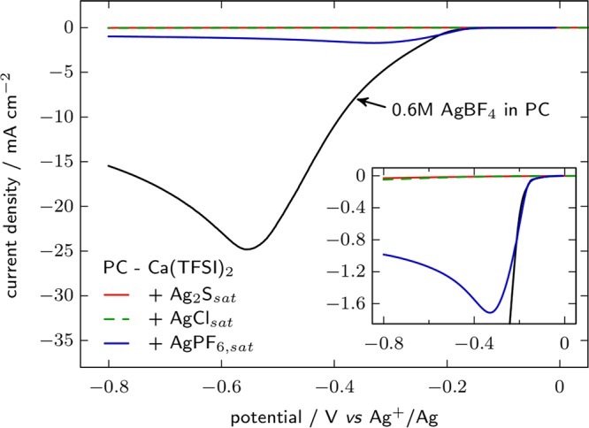
Ag plating on a stainless steel plunger by linear sweep voltammetry at 20 mV s–1 in 0.6 M AgBF4 in PC and saturated solutions of Ag2S, AgCl, or AgPF6 in PC with 0.1 M Ca(TFSI)2 as the supporting electrolyte, at room temperature. A Ag wire reference and an activated carbon counter electrode were employed
Ag2S is about 20 times less soluble than AgCl in 154 mM aqueous NaCl solution.124 Regarding organic solutions, we immersed 12 cm bare Ag wire or coated with Ag2S (∼50 mg Ag in either case) in 1.5 mL of LP30 electrolyte for 10 days at room temperature. No Ag (<0.2 ppm) could be detected by ICP-MS after immersion of either Ag or Ag2S in the electrolyte. Ag/Ag2S can be easily prepared by dipping a Ag wire in ammonium sulfide.125 Though the oxidized form of the redox couple is identified, the voltage of the Ag/Ag2S reference is not well-defined unless the concentration in S at the vicinity of the electrode is controlled.126
In Figure 10 the potential stability of Ag and Ag/Ag2S electrodes in EC:DMC with either 1 M LiPF6 or 1 M LiTFSI as the electrolyte is reported. Their potential is obtained from the redox potential of Fc+/Fc, which was measured by cyclic voltammetry on stainless steel WE and AC as CE, with 5 mM ferrocene added in the electrolyte. For each case the voltage of two cells at room temperature is reported. Gradual loss of the Fc+/Fc peak current was observed in combination with LiPF6 so that the experiment could only last for 20 to 40 h with this salt, depending on the cell. Comparison of parts a and b of Figure 10 shows a better repeatability for the potential of Ag/Ag2S electrodes than for Ag electrodes, and no difference between PF6– and TFSI– anions in the case of Ag/Ag2S. Coating of the Ag wire with the sulfide layer appears as an improvement with respect to the use of the bare metal wire as QRE regarding the stability of the potential; however, it might not always be desirable to have the Ag2S layer in direct contact with the test solution. Direct contact with the solution can be prevented either by placing the RE in a dedicated compartment, ionically connected by a frit,126 or by coating it with a photopolymerized gel electrolyte.124 Following the polymer electrolyte approach, we coated the Ag/Ag2S reference element with Nafion from a commercial suspension once attached to its plunger and subsequently exchanged the Na+ of the ionomer for Ca2+. Unfortunately, the references obtained with this method display dramatically increased stabilization times of ≥50 h. Most likely this effect is related to the stronger bonding of divalent cations with the polymer backbone of Nafion in calciated form, resulting in very low solvent uptake (2% in mass) and therefore long equilibration times. Alternative ionomers might be considered to solve this issue.
Figure 10.
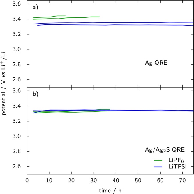
Potential of Ag (a) and Ag/Ag2S (b) quasi-reference electrodes in lithium cells with EC:DMC and 1 M LiPF6 or LiTFSI as electrolyte versus time at room temperature. Ferrocene (5 mM) was added in the electrolyte as the internal redox standard, the potential of which was measured by cyclic voltammetry (20 mV s–1) on the stainless steel plunger as a working electrode and YP17 activated carbon counter electrode. Two curves corresponding to two identical cells are plotted in each case.
Moving to the CE, and in order to illustrate the benefit of the cell setup consisting of a carbonaceous CE in combination with a Ag/Ag2S QRE, Figure 11 reports galvanostatic charge and discharge voltage profiles for TiS2 cycled in 0.1 M Ca(TFSI)2 in PC, with either a Ca metal or an AC CE. The cells are cycled at C/100 (C ⇔ 1 Ca inserted in TiS2) between −2 and 0.6 V vs Ag/Ag2S with Δx in CaxTiS2 limited to 1.2. The potentials are reported versus the Ag/Ag2S QRE, which has a potential of −40 ± 25 mV versus Fc+/Fc at 100 °C. First, a conventional half cell setup is used with a Ca metal disk as the CE, and upon first discharge its potential stabilizes around −1.65 V vs Ag/Ag2S (Figure 11a). This value appears very high given that the voltage of the QRE is 3.42 V vs Ca2+/Ca at room temperature, suggesting that Ca stripping at the CE is very unfavored. As the current is reversed after 120 h, the CE potential drops below −4 V vs Ag/Ag2S and keeps decreasing dramatically after a local minimum at −4.7 V. After 32 h of charge the voltage is higher than 11 V between the RE and the CE and the experiment is stopped for reaching a safety limit of the potentiostat. On the other hand, in Figure 11b an AC CE is used, which was previously calciated in a two-electrode carbon/carbon cell at room temperature. During the discharge of TiS2, Ca2+ ions are released from the CE, the potential of which monotonously increases from −0.60 to 0.04 V vs Ag/Ag2S. For subsequent TiS2 charge and discharge, reversible charge storage at CE ensures that its potential remains in a safe window of [−0.35:0.05] V vs Ag/Ag2S, thus permitting two complete cycles to be performed in more than 450 h.
Figure 11.
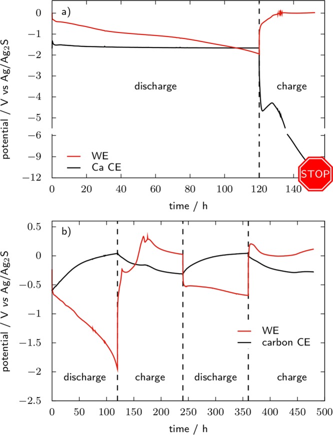
WE and CE voltage vs Ag/Ag2S QRE during galvanostatic cycling of TiS2 WE in 0.1 M Ca(TFSI)2 in PC at 100 °C. CEs are a disk of Ca metal and a precharged activated carbon electrode (YP17, 49 mg, PTFE binder), respectively.
Clearly, a large amount of side reactions occurs during cycling of the TiS2 electrode at 100 °C since at every charge or discharge a capacity corresponding to the reaction of 1.2 Ca per formula unit is passed through the cell, which is 20% higher than the capacity corresponding to the TiII/TiIV redox process. Several voltage maxima at charge also look suspicious, though some of them might be associated with energy barriers for phase transitions. Nevertheless, Figure 11 shows that the use of a QRE such as Ag/Ag2S in combination with a carbonaceous CE that relies on simple electrostatic charge storage allows the reactions occurring during cycling of an active material to be studied in electrolytes for which the plating of divalent cations is impossible. Such a setup significantly broadens the possibilities in comparison to the use of metallic CEs that hardly allow for more than the reduction of a material, which therefore must be a cation host rather than a cation source, and with possible release in the electrolyte of products of side reactions at the CE.
Summary
To study materials for post-Li-ion batteries, the experimental setup used in Li cells cannot be simply transposed to other systems, especially regarding the use of a piece of metal as the RE or CE. Na and Ca or Mg illustrate two opposed cases: on Na a less stable SEI is formed than on Li, which brings problems related with extensive electrolyte decomposition and contamination with the soluble decomposition products; on Ca and Mg the surface layer is in most cases rather a passivation layer than an actual SEI, so that their rest potential does not correspond to the equilibrium potential that a pure metallic surface would theoretically have in the electrolyte and plating or stripping reactions are impeded. In either case, replacing metal electrodes by other types of REs and CEs improves the reliability of electrochemical tests. For a most reliable setup, such alternative RE and CE should operate within the voltage stability window of the electrolyte.
An example of the use of an AC as a CE in combination with a QRE (Ag/Ag2S) as an alternative electrochemical setup for battery material (anode and cathode active material and electrolyte) testing is presented. The reliability of such a setup is demonstrated with the case of TiS2 cycling in a Ca electrolyte, which does not allow for plating and stripping. However, such improved reliability in comparison to setups using the metal electrode as the RE and CE can only be achieved through careful consideration of the voltage stability and chemical compatibility of the electrolyte with the QRE and sizing of the AC electrode, the latter having relatively low capacity (<30 mAh·g–1). Depending on the configuration, precharging of the AC CE prior to material testing might be needed. Finally, three-electrode cell configuration should be used in most cases and, similar to the Li system, cell geometry and positioning of the RE with respect to the WE and CE are crucial, especially for impedance measurements.
Acknowledgments
Funding from the European Research Council (ERC) under the European Union’s Horizon 2020 research and innovation programme (Grant Agreement No. 715087) and doctoral cofund program H2020-MSCA-COFUND-2016 (DOC-FAM, Grant Agreement No. 754397) is acknowledged. Financial support from the Spanish Ministry for Economy, Industry and Competitiveness through the Severo Ochoa Programme for Centres of Excellence in R&D (SEV-2015-0496) is also acknowledged. R.D. acknowledges support of the Beatriu de Pinós postdoctoral programme of the Government of Catalonia’s Secretariat for Universities and Research of the Ministry of Economy and Knowledge (2017 BP 00187). J.D.F.-S. contributed to this work in the frame of the Doctoral Degree Program in Materials Science by the Universitat Autònoma de Barcelona. We thank Drs. A. P. Black and R. Verrelli for providing us with some of the material that was employed in this work.
The authors declare no competing financial interest.
References
- Van Noorden R. The rechargeable revolution: A better battery. Nature 2014, 507, 26. 10.1038/507026a. [DOI] [PubMed] [Google Scholar]
- Tarascon J.-M. Is lithium the new gold?. Nat. Chem. 2010, 2, 510. 10.1038/nchem.680. [DOI] [PubMed] [Google Scholar]
- Canepa P.; Sai Gautam G.; Hannah D. C.; Malik R.; Liu M.; Gallagher K. G.; Persson K. A.; Ceder G. Odyssey of Multivalent Cathode Materials: Open Questions and Future Challenges. Chem. Rev. 2017, 117, 4287–4341. 10.1021/acs.chemrev.6b00614. [DOI] [PubMed] [Google Scholar]
- Ponrouch A.; Bitenc J.; Dominko R.; Lindahl N.; Johansson P.; Palacin M. R. Multivalent rechargeable batteries. Energy Storage Materials 2019, 20, 253–262. 10.1016/j.ensm.2019.04.012. [DOI] [Google Scholar]
- Burrows B.; Jasinski R. The Li/Li+ Reference Electrode in Propylene Carbonate. J. Electrochem. Soc. 1968, 115, 365–367. 10.1149/1.2411199. [DOI] [Google Scholar]
- Rudola A.; Aurbach D.; Balaya P. A New Phenomenon in Sodium Batteries: Voltage Step Due to Solvent Interaction. Electrochem. Commun. 2014, 46, 56–59. 10.1016/j.elecom.2014.06.008. [DOI] [Google Scholar]
- Iermakova D. I.; Dugas R.; Palacín M. R.; Ponrouch A. On the Comparative Stability of Li and Na Metal Anode Interfaces in Conventional Alkyl Carbonate Electrolytes. J. Electrochem. Soc. 2015, 162, A7060–A7066. 10.1149/2.0091513jes. [DOI] [Google Scholar]
- Dugas R.; Ponrouch A.; Gachot G.; David R.; Palacin M. R.; Tarascon J. M. Na Reactivity toward Carbonate-Based Electrolytes: The Effect of FEC as Additive. J. Electrochem. Soc. 2016, 163, A2333–A2339. 10.1149/2.0981610jes. [DOI] [Google Scholar]
- Tchitchekova D. S.; Monti D.; Johansson P.; Bardé F.; Randon-Vitanova A.; Palacín M. R.; Ponrouch A. On the Reliability of Half-Cell Tests for Monovalent (Li+, Na+) and Divalent (Mg2+, Ca2+) Cation Based Batteries. J. Electrochem. Soc. 2017, 164, A1384–A1392. 10.1149/2.0411707jes. [DOI] [Google Scholar]
- Marks T.; Trussler S.; Smith A. J.; Xiong D.; Dahn J. R. A Guide to Li-Ion Coin-Cell Electrode Making for Academic Researchers. J. Electrochem. Soc. 2011, 158, A51–A57. 10.1149/1.3515072. [DOI] [Google Scholar]
- Talaie E.; Bonnick P.; Sun X.; Pang Q.; Liang X.; Nazar L. F. Methods and Protocols for Electrochemical Energy Storage Materials Research. Chem. Mater. 2017, 29, 90–105. 10.1021/acs.chemmater.6b02726. [DOI] [Google Scholar]
- Gamby J.; Taberna P.; Simon P.; Fauvarque J.; Chesneau M. Studies and characterisations of various activated carbons used for carbon/carbon supercapacitors. J. Power Sources 2001, 101, 109–116. 10.1016/S0378-7753(01)00707-8. [DOI] [Google Scholar]
- Guyomard D.; Tarascon J. M. Li Metal-Free Rechargeable LiMn2 O 4/Carbon Cells: Their Understanding and Optimization. J. Electrochem. Soc. 1992, 139, 937–948. 10.1149/1.2069372. [DOI] [Google Scholar]
- Periyapperuma K.; Tran T. T.; Trussler S.; Ioboni D.; Obrovac M. N. Conflat Two and Three Electrode Electrochemical Cells. J. Electrochem. Soc. 2014, 161, A2182–A2187. 10.1149/2.0721414jes. [DOI] [Google Scholar]
- Murray V.; Hall D. S.; Dahn J. R. A Guide to Full Coin Cell Making for Academic Researchers. J. Electrochem. Soc. 2019, 166, A329–A333. 10.1149/2.1171902jes. [DOI] [Google Scholar]
- Stevens D. A.; Dahn J. R. High Capacity Anode Materials for Rechargeable Sodium-Ion Batteries. J. Electrochem. Soc. 2000, 147, 1271–1273. 10.1149/1.1393348. [DOI] [Google Scholar]
- Abraham D. P.; Poppen S. D.; Jansen A. N.; Liu J.; Dees D. W. Application of a lithium–tin reference electrode to determine electrode contributions to impedance rise in high-power lithium-ion cells. Electrochim. Acta 2004, 49, 4763–4775. 10.1016/j.electacta.2004.05.040. [DOI] [Google Scholar]
- Delacourt C.; Ridgway P. L.; Srinivasan V.; Battaglia V. Measurements and Simulations of Electrochemical Impedance Spectroscopy of a Three-Electrode Coin Cell Design for Li-Ion Cell Testing. J. Electrochem. Soc. 2014, 161, A1253–A1260. 10.1149/2.0311409jes. [DOI] [Google Scholar]
- Juarez-Robles D.; Chen C.-F.; Barsukov Y.; Mukherjee P. P. Impedance Evolution Characteristics in Lithium-Ion Batteries. J. Electrochem. Soc. 2017, 164, A837–A847. 10.1149/2.1251704jes. [DOI] [Google Scholar]
- Le Fevre L. W.; Fields R.; Redondo E.; Todd R.; Forsyth A. J.; Dryfe R. A. Cell optimization of supercapacitors using a quasi-reference electrode and potentiostatic analysis. J. Power Sources 2019, 424, 52–60. 10.1016/j.jpowsour.2019.03.062. [DOI] [Google Scholar]
- Wang D. Y.; Xia J.; Ma L.; Nelson K. J.; Harlow J. E.; Xiong D.; Downie L. E.; Petibon R.; Burns J. C.; Xiao A.; Lamanna W. M.; Dahn J. R. A Systematic Study of Electrolyte Additives in Li[Ni1/3Mn1/3Co1/3]O2 (NMC)/Graphite Pouch Cells. J. Electrochem. Soc. 2014, 161, A1818–A1827. 10.1149/2.0511412jes. [DOI] [Google Scholar]
- Wang H.; Liao X.-Z.; Yang Y.; Yan X.; He Y.-S.; Ma Z.-F. Large-Scale Synthesis of NaNi1/3Fe1/3Mn1/3O2 as High Performance Cathode Materials for Sodium Ion Batteries. J. Electrochem. Soc. 2016, 163, A565–A570. 10.1149/2.0011605jes. [DOI] [Google Scholar]
- Yan G.; Dugas R.; Tarascon J.-M. The Na3V2(PO4)2F3/Carbon Na-Ion Battery: Its Performance Understanding as Deduced from Differential Voltage Analysis. J. Electrochem. Soc. 2018, 165, A220–A227. 10.1149/2.0831802jes. [DOI] [Google Scholar]
- Robba A.; Vizintin A.; Bitenc J.; Mali G.; Arčon I.; Kavčič M.; Žitnik M.; Bučar K.; Aquilanti G.; Martineau-Corcos C.; Randon-Vitanova A.; Dominko R. Mechanistic Study of Magnesium–Sulfur Batteries. Chem. Mater. 2017, 29, 9555–9564. 10.1021/acs.chemmater.7b03956. [DOI] [Google Scholar]
- Yamada Y.; Iriyama Y.; Abe T.; Ogumi Z. Kinetics of Lithium Ion Transfer at the Interface between Graphite and Liquid Electrolytes: Effects of Solvent and Surface Film. Langmuir 2009, 25, 12766–12770. 10.1021/la901829v. [DOI] [PubMed] [Google Scholar]
- Klink S.; Madej E.; Ventosa E.; Lindner A.; Schuhmann W.; La Mantia F. The importance of cell geometry for electrochemical impedance spectroscopy in three-electrode lithium ion battery test cells. Electrochem. Commun. 2012, 22, 120–123. 10.1016/j.elecom.2012.06.010. [DOI] [Google Scholar]
- Costard J.; Ender M.; Weiss M.; Ivers-Tiffée E. Three-Electrode Setups for Lithium-Ion Batteries: II. Experimental Study of Different Reference Electrode Designs and Their Implications for Half-Cell Impedance Spectra. J. Electrochem. Soc. 2017, 164, A80–A87. 10.1149/2.0241702jes. [DOI] [Google Scholar]
- Morcrette M.; Chabre Y.; Vaughan G.; Amatucci G.; Leriche J.-B.; Patoux S.; Masquelier C.; Tarascon J.-M. In situ X-ray diffraction techniques as a powerful tool to study battery electrode materials. Electrochim. Acta 2002, 47, 3137–3149. 10.1016/S0013-4686(02)00233-5. [DOI] [Google Scholar]
- Villevieille C.; Sasaki T.; Novák P. Novel electrochemical cell designed for operando techniques and impedance studies. RSC Adv. 2014, 4, 6782–6789. 10.1039/c3ra46184j. [DOI] [Google Scholar]
- Vizintin A.; Bitenc J.; Kopač Lautar A.; Pirnat K.; Grdadolnik J.; Stare J.; Randon-Vitanova A.; Dominko R. Probing electrochemical reactions in organic cathode materials via in operando infrared spectroscopy. Nat. Commun. 2018, 9, 661. 10.1038/s41467-018-03114-1. [DOI] [PMC free article] [PubMed] [Google Scholar]
- Jacquet Q.; Iadecola A.; Saubanère M.; Lemarquis L.; Berg E. J.; Alves Dalla Corte D.; Rousse G.; Doublet M.-L.; Tarascon J.-M. Competition between Metal Dissolution and Gas Release in Li-Rich Li3RuyIr1–yO4Model Compounds Showing Anionic Redox. Chem. Mater. 2018, 30, 7682–7690. 10.1021/acs.chemmater.8b02955. [DOI] [Google Scholar]
- Tsiouvaras N.; Meini S.; Buchberger I.; Gasteiger H. A. A Novel On-Line Mass Spectrometer Design for the Study of Multiple Charging Cycles of a Li-O2 Battery. J. Electrochem. Soc. 2013, 160, A471–A477. 10.1149/2.042303jes. [DOI] [Google Scholar]
- Pecher O.; Carretero-González J.; Griffith K. J.; Grey C. P. Materials’ Methods: NMR in Battery Research. Chem. Mater. 2017, 29, 213–242. 10.1021/acs.chemmater.6b03183. [DOI] [Google Scholar]
- Levi M. D.; Dargel V.; Shilina Y.; Aurbach D.; Halalay I. C. Impedance Spectra of Energy-Storage Electrodes Obtained with Commercial Three-Electrode Cells: Some Sources of Measurement Artefacts. Electrochim. Acta 2014, 149, 126–135. 10.1016/j.electacta.2014.10.083. [DOI] [Google Scholar]
- Wünsch M.; Füßler R.; Sauer D. U. Metrological examination of an impedance model for a porous electrode in cyclic aging using a 3-electrode lithium-ion cell with NMC111 | Graphite. Journal of Energy Storage 2018, 20, 196–203. 10.1016/j.est.2018.09.010. [DOI] [Google Scholar]
- Morita M.; Shibata T.; Yoshimoto N.; Ishikawa M. Anodic behavior of aluminum in organic solutions with different electrolytic salts for lithium ion batteries. Electrochim. Acta 2002, 47, 2787–2793. 10.1016/S0013-4686(02)00164-0. [DOI] [Google Scholar]
- Keyzer E. N.; Matthews P. D.; Liu Z.; Bond A. D.; Grey C. P.; Wright D. S. Synthesis of Ca(PF6)2, formed via nitrosonium oxidation of calcium. Chem. Commun. 2017, 53, 4573–4576. 10.1039/C7CC01938F. [DOI] [PubMed] [Google Scholar]
- Pardo A.; Merino M.; Coy A.; Viejo F.; Arrabal R.; Matykina E. Effect of Mo and Mn additions on the corrosion behaviour of AISI 304 and 316 stainless steels in H2SO4. Corros. Sci. 2008, 50, 780–794. 10.1016/j.corsci.2007.11.004. [DOI] [Google Scholar]
- Sinha N. N.; Burns J.; Sanderson R.; Dahn J. Comparative Studies of Hardware Corrosion at High Potentials in Coin-Type Cells with Non Aqueous Electrolytes. J. Electrochem. Soc. 2011, 158, A1400–A1403. 10.1149/2.080112jes. [DOI] [Google Scholar]
- Westman K.; Dugas R.; Jankowski P.; Wieczorek W.; Gachot G.; Morcrette M.; Irisarri E.; Ponrouch A.; Palacín M. R.; Tarascon J.-M.; Johansson P. Diglyme Based Electrolytes for Sodium-Ion Batteries. ACS Appl. Energy Mater. 2018, 1, 2671–2680. 10.1021/acsaem.8b00360. [DOI] [Google Scholar]
- Besenhard J. Cycling behaviour and corrosion of Li-Al electrodes in organic electrolytes. J. Electroanal. Chem. Interfacial Electrochem. 1978, 94, 77–81. 10.1016/S0022-0728(78)80400-8. [DOI] [Google Scholar]
- Ponrouch A.; Marchante E.; Courty M.; Tarascon J.-M.; Palacín M. R. In search of an optimized electrolyte for Na-ion batteries. Energy Environ. Sci. 2012, 5, 8572–8583. 10.1039/c2ee22258b. [DOI] [Google Scholar]
- Bale C. W.; Bélisle E. Fact-Web suite of interactive programs, www.factsage.com.
- Murgia F.; Stievano L.; Monconduit L.; Berthelot R. Insight into the electrochemical behavior of micrometric Bi and Mg3Bi2 as high performance negative electrodes for Mg batteries. J. Mater. Chem. A 2015, 3, 16478–16485. 10.1039/C5TA04077A. [DOI] [Google Scholar]
- Murgia F.; Weldekidan E. T.; Stievano L.; Monconduit L.; Berthelot R. First investigation of indium-based electrode in Mg battery. Electrochem. Commun. 2015, 60, 56–59. 10.1016/j.elecom.2015.08.007. [DOI] [Google Scholar]
- Merrill L. C.; Schaefer J. L. Conditioning-Free Electrolytes for Magnesium Batteries Using Sufone–Ether Mixtures with Increased Thermal Stability. Chem. Mater. 2018, 30, 3971–3974. 10.1021/acs.chemmater.8b00483. [DOI] [Google Scholar]
- Tchitchekova D. S.; Ponrouch A.; Verrelli R.; Broux T.; Frontera C.; Sorrentino A.; Bardé F.; Biskup N.; Arroyo-de Dompablo M. E.; Palacín M. R. Electrochemical Intercalation of Calcium and Magnesium in TiS2: Fundamental Studies Related to Multivalent Battery Applications. Chem. Mater. 2018, 30, 847–856. 10.1021/acs.chemmater.7b04406. [DOI] [Google Scholar]
- Verrelli R.; Black A.; Pattanathummasid C.; Tchitchekova D.; Ponrouch A.; Oró-Solé J.; Frontera C.; Bardé F.; Rozier P.; Palacín M. On the strange case of divalent ions intercalation in V2O5. J. Power Sources 2018, 407, 162–172. 10.1016/j.jpowsour.2018.08.024. [DOI] [Google Scholar]
- Bitenc J.; Dominko R. Opportunities and Challenges in the Development of Cathode Materials for Rechargeable Mg Batteries. Front. Chem. 2018, 6, 634. 10.3389/fchem.2018.00634. [DOI] [PMC free article] [PubMed] [Google Scholar]
- Lutz L.; Alves Dalla Corte D.; Tang M.; Salager E.; Deschamps M.; Grimaud A.; Johnson L.; Bruce P. G.; Tarascon J.-M. Role of Electrolyte Anions in the Na–O2 Battery: Implications for NaO2 Solvation and the Stability of the Sodium Solid Electrolyte Interphase in Glyme Ethers. Chem. Mater. 2017, 29, 6066–6075. 10.1021/acs.chemmater.7b01953. [DOI] [Google Scholar]
- Garcia G.; Schuhmann W.; Ventosa E. A Three-Electrode, Battery-Type Swagelok Cell for the Evaluation of Secondary Alkaline Batteries: The Case of the Ni–Zn Battery. ChemElectroChem 2016, 3, 592–597. 10.1002/celc.201500474. [DOI] [Google Scholar]
- Bünzli C.; Kaiser H.; Novák P. Important Aspects for Reliable Electrochemical Impedance Spectroscopy Measurements of Li-Ion Battery Electrodes. J. Electrochem. Soc. 2015, 162, A218–A222. 10.1149/2.1061501jes. [DOI] [Google Scholar]
- Tan C.; Daemi S. R.; Taiwo O. O.; Heenan T. M. M.; Brett D. J. L.; Shearing P. R. Evolution of Electrochemical Cell Designs for In-Situ and Operando 3D Characterization. Materials 2018, 11, 2157. 10.3390/ma11112157. [DOI] [PMC free article] [PubMed] [Google Scholar]
- Tasker S.; Chambers R. D.; Badyal J. P. S. Surface Defluorination of PTFE by Sodium Atoms. J. Phys. Chem. 1994, 98, 12442–12446. 10.1021/j100098a046. [DOI] [Google Scholar]
- Hlavatý J.; Kavan L. The preparation of polymeric carbon from PTFE in the suspension of alkali metals. Carbon 1999, 37, 1029–1032. 10.1016/S0008-6223(98)00295-4. [DOI] [Google Scholar]
- Li G.; Xue R.; Chen L. The influence of polytetrafluorethylene reduction on the capacity loss of the carbon anode for lithium ion batteries. Solid State Ionics 1996, 90, 221–225. 10.1016/S0167-2738(96)00367-0. [DOI] [Google Scholar]
- Lim H. S.; Margerum J. D.; Verzwyvelt S. A.; Lackner A. M.; Knechtli R. C. Degradation Mechanisms of Nylon Separator Materials for a Nickel-Cadmium Cell in KOH Electrolytes. J. Electrochem. Soc. 1989, 136, 605–612. 10.1149/1.2096696. [DOI] [Google Scholar]
- Cuscueta D.; Ghilarducci A.; Salva H. Design, elaboration and characterization of a Ni–MH battery prototype. Int. J. Hydrogen Energy 2010, 35, 11315–11323. 10.1016/j.ijhydene.2010.07.020. [DOI] [Google Scholar]
- Wypych G.Handbook of Polymers, 2nd ed.; ChemTec Publishing: 2016. [Google Scholar]
- Arora P.; Zhang Z. Battery Separators. Chem. Rev. 2004, 104, 4419–4462. 10.1021/cr020738u. [DOI] [PubMed] [Google Scholar]
- Lee H.; Yanilmaz M.; Toprakci O.; Fu K.; Zhang X. A review of recent developments in membrane separators for rechargeable lithium-ion batteries. Energy Environ. Sci. 2014, 7, 3857–3886. 10.1039/C4EE01432D. [DOI] [Google Scholar]
- Bierenbaum H. S.; Isaacson R. B.; Druin M. L.; Plovan S. G. Microporous Polymeric Films. Ind. Eng. Chem. Prod. Res. Dev. 1974, 13, 2–9. 10.1021/i360049a002. [DOI] [Google Scholar]
- Wiemers-Meyer S.; Jeremias S.; Winter M.; Nowak S. Influence of Battery Cell Components and Water on the Thermal and Chemical Stability of LiPF6 Based Lithium Ion Battery Electrolytes. Electrochim. Acta 2016, 222, 1267–1271. 10.1016/j.electacta.2016.11.100. [DOI] [Google Scholar]
- Noh J.; Laycock N.; Gao W.; Wells D. Effects of nitric acid passivation on the pitting resistance of 316 stainless steel. Corros. Sci. 2000, 42, 2069–2084. 10.1016/S0010-938X(00)00052-4. [DOI] [Google Scholar]
- Peled E. Film forming reaction at the lithium/electrolyte interface. J. Power Sources 1983, 9, 253–266. 10.1016/0378-7753(83)87026-8. [DOI] [Google Scholar]
- Aurbach D.; Zinigrad E.; Cohen Y.; Teller H. A short review of failure mechanisms of lithium metal and lithiated graphite anodes in liquid electrolyte solutions. Solid State Ionics 2002, 148, 405–416. 10.1016/S0167-2738(02)00080-2. [DOI] [Google Scholar]
- La Mantia F.; Wessells C.; Deshazer H.; Cui Y. Reliable reference electrodes for lithium-ion batteries. Electrochem. Commun. 2013, 31, 141–144. 10.1016/j.elecom.2013.03.015. [DOI] [Google Scholar]
- Mogensen R.; Brandell D.; Younesi R. Solubility of the Solid Electrolyte Interphase (SEI) in Sodium Ion Batteries. ACS Energy Lett. 2016, 1, 1173–1178. 10.1021/acsenergylett.6b00491. [DOI] [Google Scholar]
- Larcher D.; Tarascon J.-M. In The Science and Practice of Lithium Therapy; Malhi G. S., Masson M., Bellivier F., Eds.; Springer International Publishing: 2017; Chapter 1, pp 3–23. [Google Scholar]
- Kim H.; Kim J. C.; Bo S.-H.; Shi T.; Kwon D.-H.; Ceder G. K-Ion Batteries Based on a P2-Type K0.6CoO2 Cathode. Adv. Energy Mater. 2017, 7, 1700098. 10.1002/aenm.201700098. [DOI] [Google Scholar]
- Madec L.; Gabaudan V.; Gachot G.; Stievano L.; Monconduit L.; Martinez H. Paving the Way for K-Ion Batteries: Role of Electrolyte Reactivity through the Example of Sb-Based Electrodes. ACS Appl. Mater. Interfaces 2018, 10, 34116–34122. 10.1021/acsami.8b08902. [DOI] [PubMed] [Google Scholar]
- Moshkovich M.; Gofer Y.; Aurbach D. Investigation of the Electrochemical Windows of Aprotic Alkali Metal (Li, Na, K) Salt Solutions. J. Electrochem. Soc. 2001, 148, E155–E167. 10.1149/1.1357316. [DOI] [Google Scholar]
- Newman J.; Thomas-Alyea K. E.. Electrochemical Systems, 3rd ed.; John Wiley & Sons, Inc.: Hoboken, NJ: 2004. [Google Scholar]
- Lee S. E.; Tang M. H. Electroactive decomposition products cause erroneous intercalation signals in sodium-ion batteries. Electrochem. Commun. 2019, 100, 70–73. 10.1016/j.elecom.2019.01.024. [DOI] [Google Scholar]
- Jiang X.; Zhang T.; Yang L.; Li G.; Lee J. Y. A Fe/Mn-Based Prussian Blue Analogue as a K-Rich Cathode Material for Potassium-Ion Batteries. ChemElectroChem 2017, 4, 2237–2242. 10.1002/celc.201700410. [DOI] [Google Scholar]
- Xiao N.; McCulloch W. D.; Wu Y. Reversible Dendrite-Free Potassium Plating and Stripping Electrochemistry for Potassium Secondary Batteries. J. Am. Chem. Soc. 2017, 139, 9475–9478. 10.1021/jacs.7b04945. [DOI] [PubMed] [Google Scholar]
- Solchenbach S.; Pritzl D.; Kong E. J. Y.; Landesfeind J.; Gasteiger H. A. A Gold Micro-Reference Electrode for Impedance and Potential Measurements in Lithium Ion Batteries. J. Electrochem. Soc. 2016, 163, A2265–A2272. 10.1149/2.0581610jes. [DOI] [Google Scholar]
- Gómez-Cámer J. L.; Novák P. Electrochemical impedance spectroscopy: Understanding the role of the reference electrode. Electrochem. Commun. 2013, 34, 208–210. 10.1016/j.elecom.2013.06.016. [DOI] [Google Scholar]
- Pritzl D.; Landesfeind J.; Solchenbach S.; Gasteiger H. A. An Analysis Protocol for Three-Electrode Li-Ion Battery Impedance Spectra: Part II. Analysis of a Graphite Anode Cycled vs. LNMO. J. Electrochem. Soc. 2018, 165, A2145–A2153. 10.1149/2.0461810jes. [DOI] [Google Scholar]
- Gregory T. D.; Hoffman R. J.; Winterton R. C. Nonaqueous Electrochemistry of Magnesium: Applications to Energy Storage. J. Electrochem. Soc. 1990, 137, 775–780. 10.1149/1.2086553. [DOI] [Google Scholar]
- Aurbach D.; Lu Z.; Schechter A.; Gofer Y.; Gizbar H.; Turgeman R.; Cohen Y.; Moshkovich M.; Levi E. Prototype systems for rechargeable magnesium batteries. Nature 2000, 407, 724–727. 10.1038/35037553. [DOI] [PubMed] [Google Scholar]
- Sa N.; Pan B.; Saha-Shah A.; Hubaud A. A.; Vaughey J. T.; Baker L. A.; Liao C.; Burrell A. K. Role of Chloride for a Simple, Non-Grignard Mg Electrolyte in Ether-Based Solvents. ACS Appl. Mater. Interfaces 2016, 8, 16002–16008. 10.1021/acsami.6b03193. [DOI] [PubMed] [Google Scholar]
- Lu Z.; Schechter A.; Moshkovich M.; Aurbach D. On the electrochemical behavior of magnesium electrodes in polar aprotic electrolyte solutions. J. Electroanal. Chem. 1999, 466, 203–217. 10.1016/S0022-0728(99)00146-1. [DOI] [Google Scholar]
- Attias R.; Salama M.; Hirsch B.; Goffer Y.; Aurbach D. Anode-Electrolyte Interfaces in Secondary Magnesium Batteries. Joule 2019, 3, 27–52. 10.1016/j.joule.2018.10.028. [DOI] [Google Scholar]
- Aurbach D.; Berthelot R.; Ponrouch A.; Salama M.; Shterenberg I.. Prospects for Li-ion Batteries and Emerging Energy Electrochemical Systems, World Scientific: 2018; Chapter 5, pp 237–318. [Google Scholar]
- Aurbach D.; Skaletsky R.; Gofer Y. The Electrochemical Behavior of Calcium Electrodes in a Few Organic Electrolytes. J. Electrochem. Soc. 1991, 138, 3536–3545. 10.1149/1.2085455. [DOI] [Google Scholar]
- Ponrouch A.; Frontera C.; Barde F.; Palacin M. R. Towards a calcium-based rechargeable battery. Nat. Mater. 2016, 15, 169–172. 10.1038/nmat4462. [DOI] [PubMed] [Google Scholar]
- Wang D.; Gao X.; Chen Y.; Jin L.; Kuss C.; Bruce P. G. Plating and stripping calcium in an organic electrolyte. Nat. Mater. 2018, 17, 16–20. 10.1038/nmat5036. [DOI] [PubMed] [Google Scholar]
- Ta K.; Zhang R.; Shin M.; Rooney R. T.; Neumann E. K.; Gewirth A. A. Understanding Ca Electrodeposition and Speciation Processes in Nonaqueous Electrolytes for Next-Generation Ca-Ion Batteries. ACS Appl. Mater. Interfaces 2019, 11, 21536–21542. 10.1021/acsami.9b04926. [DOI] [PubMed] [Google Scholar]
- Gershinsky G.; Yoo H. D.; Gofer Y.; Aurbach D. Electrochemical and Spectroscopic Analysis of Mg2+ Intercalation into Thin Film Electrodes of Layered Oxides: V2O5 and MoO3. Langmuir 2013, 29, 10964–10972. 10.1021/la402391f. [DOI] [PubMed] [Google Scholar]
- Sun X.; Duffort V.; Mehdi B. L.; Browning N. D.; Nazar L. F. Investigation of the Mechanism of Mg Insertion in Birnessite in Nonaqueous and Aqueous Rechargeable Mg-Ion Batteries. Chem. Mater. 2016, 28, 534–542. 10.1021/acs.chemmater.5b03983. [DOI] [Google Scholar]
- Lim S.-C.; Lee J.; Kwak H. H.; Heo J. W.; Chae M. S.; Ahn D.; Jang Y. H.; Lee H.; Hong S.-T. Unraveling the Magnesium-Ion Intercalation Mechanism in Vanadium Pentoxide in a Wet Organic Electrolyte by Structural Determination. Inorg. Chem. 2017, 56, 7668–7678. 10.1021/acs.inorgchem.7b00204. [DOI] [PubMed] [Google Scholar]
- Aragón M. J.; Lavela P.; Recio P.; Alcántara R.; Tirado J. L. On the influence of particle morphology to provide high performing chemically desodiated C@NaV2(PO4)3 as cathode for rechargeable magnesium batteries. J. Electroanal. Chem. 2018, 827, 128–136. 10.1016/j.jelechem.2018.09.013. [DOI] [Google Scholar]
- Attias R.; Salama M.; Hirsch B.; Gofer Y.; Aurbach D. Solvent Effects on the Reversible Intercalation of Magnesium-Ions into V2O5 Electrodes. ChemElectroChem 2018, 5, 3514–3524. 10.1002/celc.201800932. [DOI] [Google Scholar]
- Cabello M.; Nacimiento F.; Alcántara R.; Lavela P.; Pérez Vicente C.; Tirado J. L. Applicability of Molybdite as an Electrode Material in Calcium Batteries: A Structural Study of Layer-type CaxMoO3. Chem. Mater. 2018, 30, 5853–5861. 10.1021/acs.chemmater.8b01116. [DOI] [Google Scholar]
- Tchitchekova D. S.; Frontera C.; Ponrouch A.; Krich C.; Bardé F.; Palacín M. R. Electrochemical calcium extraction from 1D-Ca3Co2O6. Dalton Trans. 2018, 47, 11298–11302. 10.1039/C8DT01754A. [DOI] [PubMed] [Google Scholar]
- Lipson A. L.; Pan B.; Lapidus S. H.; Liao C.; Vaughey J. T.; Ingram B. J. Rechargeable Ca-Ion Batteries: A New Energy Storage System. Chem. Mater. 2015, 27, 8442–8447. 10.1021/acs.chemmater.5b04027. [DOI] [Google Scholar]
- Periyapperuma K.; Tran T. T.; Purcell M.; Obrovac M. The Reversible Magnesiation of Pb. Electrochim. Acta 2015, 165, 162–165. 10.1016/j.electacta.2015.03.006. [DOI] [Google Scholar]
- Elgrishi N.; Rountree K. J.; McCarthy B. D.; Rountree E. S.; Eisenhart T. T.; Dempsey J. L. A Practical Beginner’s Guide to Cyclic Voltammetry. J. Chem. Educ. 2018, 95, 197–206. 10.1021/acs.jchemed.7b00361. [DOI] [Google Scholar]
- Connell J. G.; Genorio B.; Lopes P. P.; Strmcnik D.; Stamenkovic V. R.; Markovic N. M. Tuning the Reversibility of Mg Anodes via Controlled Surface Passivation by H2O/Cl– in Organic Electrolytes. Chem. Mater. 2016, 28, 8268–8277. 10.1021/acs.chemmater.6b03227. [DOI] [Google Scholar]
- Thompson A. H. Electrochemical Potential Spectroscopy: A New Electrochemical Measurement. J. Electrochem. Soc. 1979, 126, 608–616. 10.1149/1.2129095. [DOI] [Google Scholar]
- Weppner W.; Huggins R. A. Determination of the Kinetic Parameters of Mixed-Conducting Electrodes and Application to the System Li3Sb. J. Electrochem. Soc. 1977, 124, 1569–1578. 10.1149/1.2133112. [DOI] [Google Scholar]
- Wen C. J.; Boukamp B. A.; Huggins R. A.; Weppner W. Thermodynamic and Mass Transport Properties of “LiAl”. J. Electrochem. Soc. 1979, 126, 2258–2266. 10.1149/1.2128939. [DOI] [Google Scholar]
- Deiss E. Spurious potential dependence of diffusion coefficients in Li+ insertion electrodes measured with PITT. Electrochim. Acta 2002, 47, 4027–4034. 10.1016/S0013-4686(02)00363-8. [DOI] [Google Scholar]
- Li J.; Xiao X.; Yang F.; Verbrugge M. W.; Cheng Y.-T. Potentiostatic Intermittent Titration Technique for Electrodes Governed by Diffusion and Interfacial Reaction. J. Phys. Chem. C 2012, 116, 1472–1478. 10.1021/jp207919q. [DOI] [Google Scholar]
- Li J.; Yang F.; Xiao X.; Verbrugge M. W.; Cheng Y.-T. Potentiostatic intermittent titration technique (PITT) for spherical particles with finite interfacial kinetics. Electrochim. Acta 2012, 75, 56–61. 10.1016/j.electacta.2012.04.050. [DOI] [Google Scholar]
- Malifarge S.; Delobel B.; Delacourt C. Guidelines for the Analysis of Data from the Potentiostatic Intermittent Titration Technique on Battery Electrodes. J. Electrochem. Soc. 2017, 164, A3925–A3932. 10.1149/2.1591714jes. [DOI] [Google Scholar]
- Lasia A. Electrochemical Impedance Spectroscopy and its Applications. Mod. Aspect. Electroc. 2002, 32, 143–248. 10.1007/0-306-46916-2_2. [DOI] [Google Scholar]
- Agarwal P.; Orazem M. E.; Garcia-Rubio L. H. Measurement Models for Electrochemical Impedance Spectroscopy: I. J. Electrochem. Soc. 1992, 139, 1917–1927. 10.1149/1.2069522. [DOI] [Google Scholar]
- http://www.gamry.com/application-notes/EIS/eis-potentiostatic-galvanostatic-mode/ (accessed July 2, 2019).
- Chen C.; Liu J.; Amine K. Symmetric cell approach and impedance spectroscopy of high power lithium-ion batteries. J. Power Sources 2001, 96, 321–328. 10.1016/S0378-7753(00)00666-2. [DOI] [Google Scholar]
- Petibon R.; Aiken C. P.; Sinha N. N.; Burns J. C.; Ye H.; VanElzen C. M.; Jain G.; Trussler S.; Dahn J. R. Study of Electrolyte Additives Using Electrochemical Impedance Spectroscopy on Symmetric Cells. J. Electrochem. Soc. 2013, 160, A117–A124. 10.1149/2.005302jes. [DOI] [Google Scholar]
- Dees D. W.; Jansen A. N.; Abraham D. P. Theoretical examination of reference electrodes for lithium-ion cells. J. Power Sources 2007, 174, 1001–1006. 10.1016/j.jpowsour.2007.06.128. [DOI] [Google Scholar]
- Portet C.; Taberna P. L.; Simon P.; Laberty-Robert C. Modification of Al current collector surface by sol–gel deposit for carbon–carbon supercapacitor applications. Electrochim. Acta 2004, 49, 905–912. 10.1016/j.electacta.2003.09.043. [DOI] [Google Scholar]
- https://www.bio-logic.net/wp-content/uploads/20101105-application-note-5.pdf (accessed July 2, 2019).
- Torriero A. A.; Sunarso J.; Howlett P. C. Critical evaluation of reference systems for voltammetric measurements in ionic liquids. Electrochim. Acta 2012, 82, 60–68. 10.1016/j.electacta.2012.01.115. [DOI] [Google Scholar]
- Ruch P.; Cericola D.; Hahn M.; Kötz R.; Wokaun A. On the use of activated carbon as a quasi-reference electrode in non-aqueous electrolyte solutions. J. Electroanal. Chem. 2009, 636, 128–131. 10.1016/j.jelechem.2009.09.007. [DOI] [Google Scholar]
- Auer A.; Kunze-Liebhäuser J. A universal quasi-reference electrode for in situ EC-STM. Electrochem. Commun. 2019, 98, 15–18. 10.1016/j.elecom.2018.11.015. [DOI] [Google Scholar]
- Snook G.; Best A.; Pandolfo A.; Hollenkamp A. Evaluation of a Ag|Ag+ reference electrode for use in room temperature ionic liquids. Electrochem. Commun. 2006, 8, 1405–1411. 10.1016/j.elecom.2006.07.004. [DOI] [Google Scholar]
- Gritzner G.; Kuta J. RECOMMENDATIONS ON REPORTING ELECTRODE POTENTIALS IN NONAQUEOUS SOLVENTS. Pure Appl. Chem. 1984, 56, 461–466. 10.1351/pac198456040461. [DOI] [Google Scholar]
- Bard A. J.; Faulkner L. R.. Electrochemical Methods – Fundamentals and Applications, 2nd ed.; John Wiley & Sons, Inc.: 2001. [Google Scholar]
- Koepp H.-M.; Wendt H.; Stkehlow H. Der Vergleich der Spannungsreihen in verschiedenen Solventien. II. Z. Elektrochem. 1960, 64, 483–491. 10.1002/bbpc.19600640406. [DOI] [Google Scholar]
- Gagne R. R.; Koval C. A.; Lisensky G. C. Ferrocene as an internal standard for electrochemical measurements. Inorg. Chem. 1980, 19, 2854–2855. 10.1021/ic50211a080. [DOI] [Google Scholar]
- Ciobanu M.; Wilburn J. P.; Buss N. I.; Ditavong P.; Lowy D. A. Miniaturized Reference Electrodes Based on Ag/AgiX Internal Reference Elements. I. Manufacturing and Performance. Electroanalysis 2002, 14, 989–997. 10.1002/1521-4109(200208)14:14<989::AID-ELAN989>3.0.CO;2-6. [DOI] [Google Scholar]
- Ciobanu M.; Wilburn J. P.; Lowy D. A. Miniaturized Reference Electrodes. II. Use in Corrosive, Biological, and Organic Media. Electroanalysis 2004, 16, 1351–1358. 10.1002/elan.200302960. [DOI] [Google Scholar]
- Horwood C.; Stadermann M. Evaluation of a Ag/Ag2S reference electrode with long-term stability for electrochemistry in ionic liquids. Electrochem. Commun. 2018, 88, 105–108. 10.1016/j.elecom.2018.02.005. [DOI] [Google Scholar]