Abstract
In the recent years, there has been a growing interest in research community towards the application of smart materials for bio-medical structural health monitoring. Amongst the smart materials, directly bonded piezo sensors (DBPS), based on the electro-mechanical impedance (EMI) technique, have been successfully employed for the above purpose. The principle behind the EMI technique is that high frequency excitations (typically > 30 kHz) generated by a surface bonded PZT patch are used to detect changes in structural drive point impedance caused by cracks or any other type of damage. Bone healing and damage have been shown to be successfully monitored using the DBPS. However, in most of the diagnostic cases of live human and animal subjects, directly bonding a PZT patch is always an irritant or hazard for a live subject. To circumvent direct bonding, the authors have developed and experimentally demonstrated a non-bonded piezo sensor (NBPS) configuration as a good alternative to DBPS while maintaining the effectiveness of measurement well within discernible limits. This paper presents further improvement in the NBPS configuration aiming at autonomous operation of the gripping mechanism using shape memory alloy (SMA) wires. The experiments are performed on replicas of femur bone in healthy and osteoporosis state. This paper shows the effective use of SMA clamping for bone identification and its damage assessment in comparison to earlier mechanical gripping using jubilee clamps. This paper also covers impedance based identification applied to SMA and clamp based NBPS configurations. In place of raw admittance signatures, effective drive point impedance is utilized for the purpose of bone diagnostics which provides a more realistic assessment of the condition of bone.
Keywords: NBPS, Shape memory alloy (SMA) based clamping, Effective drive point impedance, Clamping factor, Osteoporosis, EMI
Introduction
In the recent years, extensive research is being pursued for employing biosensors that inflict minimal harm to the live subject. To avoid cumbersome diagnostic techniques and pain to the patients, new techniques are being devised to achieve non-invasive and wearable type of biosensors. Kim et al. [1] conducted electromyography signal based muscle fatigue assessment for knee rehabilitation monitoring systems. Dong and Biswas [2] monitored liquid intake of a human being via apneas extracted from breathing signal captured by a wearable chest sensor belt. Lim et al. [3] employed non-intrusive sensors in daily life for monitoring physiological signals. Smart materials, such as piezoelectric lead zirconate titanate (PZT) family of ceramics, due to their miniature size and good sensing as well as actuation capabilities, find vast employment in biomedical structural health monitoring (BSHM). For example, successful monitoring of bone healing and damage has been experimentally demonstrated through directly bonded piezo sensor (DBPS) [4, 5]. In line with the already established fact, mechanical properties of the bone like stiffness, density, Young’s modulus and damping can be utilized for detecting damage/deterioration since these undergo change on occurrence of any defect [6, 7]. Biological processes, especially ageing and disease such as osteoporosis lead to change in the structure of bones, thereby resulting in bone density, strength and stiffness loss. Boemio et al. [8] demonstrated the feasibility of a non-invasive technique based on the EMI principle to assess dental prostheses stability. Ribolla and Rizzo [9] successfully assessed the mechanical interlock of a dental implant with the surrounding bone, again using the EMI technique. They successfully demonstrated the capability of the EMI technique to evaluate the implant-bone interface properties by means of DBPS. DBPS, however, is constrained for widespread biomedical applications due to the fact that bonding the piezo patch with an adhesive shall result in discomfort and disease for a live subject. Laboratory based experiments that offer non-bonded piezo sensor (NBPS) as a good alternative to DBPS while maintaining the effectiveness of the measurement, were successfully conducted by authors [10]. The NBPS configuration comprises of an aluminium strip with a piezo patch bonded to the centre of the strip. In order to ensure proper interaction with the host structure, the NBPS has to be properly secured on the surface of the structure. In the previous system proposed by authors, jubilee clamps were employed [10] and circumferential strain was measured for the best possible configuration as 316 µm/m. Still, due to the mechanical means of tightening the clamps via screws, there is a tendency of bending of aluminium strip which may result in damage to the PZT patch itself. Also, the process is a bit tedious for field applications and the tightening may cause discomfort to the subject. Thus, there is a strong need to employ a fast and automated means of gripping with mechanical interaction between bones and NBPS as equally effective as that of the jubilee clamps.
Some categories of metallic alloys have special ability to memorize their shape at a low prolonged temperature, and on deformation, return to their predeformed shape upon heating beyond their “transition temperature” These alloys are called shape memory alloys (SMA).The recovery of strains induced in the material at low temperatures, carried out by heating is called the shape memory effect (SME).
Buehler and Wiley [11, 12] discovered a Nickel–Titanium alloy in 1961 called nitinol (NiTi) that exhibited a much greater shape memory effect than the previous materials. Raychem Corporation was the first to successfully employ SMA in fasteners and tube couplings for the hydraulic system of the F-14 aircraft. The shrinkage of the Ni–Ti tube diameter at high temperature resulted in sealing of the joint with the couplings. This paper presents the development of an automated gripping for NBPS to the host surface, employing shape memory alloy (SMA) wires [13] as an alternative to jubilee clamps.
This paper also applies a new approach for bone identification and osteoporosis detection using impedance based equivalent stiffness and mass parameters. In the past, quantitative assessment of the elastic properties of resected human breast tissue samples subjected to axial compressive loading in vitro was conducted using optical coherence tomographic (OCT) elastography technique [14]. Besides this, the onset and quantification of carbonation induced corrosion was detected using impedance based equivalent parameters [15]. Li et al. [16] proposed a novel corrosion monitoring method wherein the EMI signatures of the smart corrosion coupon (SCC) under varying degree of corrosion were acquired and analyzed. The novelty of the experiment lies in the fact that unlike all previous studies [17, 18], the parameters correspond to different bone specimens instrumented with different PZT patches. All previous studies, on the other hand, monitored degradation of same component using the same PZT patch. In addition to this, a new expression for admittance of PZT patch attached to the bone is also formulated. The forthcoming sections of the paper cover a brief introduction to EMI technique, NBPS configuration, experimental details and impedance-based analysis.
EMI technique: DBPS and NBPS configuration
In the EMI technique, a PZT patch is bonded to the host structure and then electrically excited over a high frequency range (30–400 kHz). When electrically excited, the patch acts as an actuator. The same patch simultaneously acts as a sensor and acquires the characteristic admittance signature of the host structure, consisting of the conductance (real part) and the susceptance (imaginary part), which serves as a unique identifier of the monitored system. The acquired signature represents the dynamic characteristics of the structure and changes discernibly on the occurrence of any changes in mechanical conditions of the host system, even though too small on macroscopic scale. This technique has especially been very effective for localized structural investigation. Lim et al. [19] assessed PZT based EMI technique for real time monitoring of curing of structural adhesives. Further Wandowski et al. [20] investigated the influence of temperature on resistance in electromechanical impedance technique. It dealt with damage detection under varying temperature.
DBPS configuration comprises of a PZT patch bonded to the surface of the subject with araldite. In the NBPS configuration, the PZT patch is first bonded to a very thin metal plate (92 × 15 × 1 mm3), which is in turn clamped on to the bone or live subject. Lu et al. [21] proposed a smart probe in which the PZT patch was not directly bonded to the host structure, but was bonded on a pre-fabricated aluminium beam, termed as smart probe. They also improved upon the model by explicitly formulating the distributed stiffness and mass of a segment of the embedded smart probe [22]. The smart probe is quite similar to the NBPS proposed earlier by the authors for biomedical health monitoring [10]. Quantification of damage and osteoporosis was also attempted [23]. Hence, there is good possibility of further exploration of NBPS in relation with the smart probe. Both DBPS and NBPS are shown in Fig. 1. In such a configuration, upon excitation by LCR meter, the PZT patch generates stationary waves on the metal plate, which interact with the host structure mechanically through the securely tied clamps. As soon as any structural change (such as damage) occurs on the host structure, the stationary waves in the metal plate and the reflected waves from the damage intermingle with one another, resulting in change of the admittance signature, providing an indication of the physical change. The clamps were tightened by rotating the ratchet with a screw driver and an electrical strain gauge instrumented on the clamp in circumferential configuration provided a measure of the tightness. The conductance signatures are acquired under three different conditions namely; (a) open clamp (b) partially tightened clamp (c) fully tightened clamp.
Fig. 1.
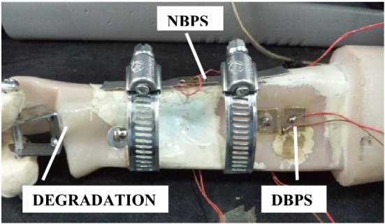
Bone with DBPS and NBPS configuration
Experimental methodology for NBPS grip automation
A 0.25 mm diameter flexinol NiTi wire (manufactured by Muscle Wires (www.musclewires.com)) which has a maximum pull force of 89.1 N at a current of 1A was employed. The NBPS strip was held against the surface of the bones by wrapping the SMA wires as shown in Fig. 2a, b. Further, from Hooke’s law, the force produced by the SMA wire is given by
| 1 |
and
| 2 |
where Y = 80 × 109 GPa is the Young’s modulus of NiTi wire, ε is the strain, d is the diameter of the wire, A is the cross-sectional area on which the force acts for a single turn of SMA wire over the bone and D (= 25 mm) is the diameter of the femur. This area represents that portion of the wire which is in contact with the bone and is thus transmitting the force to the bone. Length of wire in one turn over the bone was 78.5 mm. As per the material data sheet provided by the manufacturer, NiTi wire of 0.25 mm diameter produces a force of 89.1 N at a current of 1 A. From these equations, strain came out to be 56.72 µm/m for 78.5 mm length of SMA wire. The strain produced in SMA wire is found to be proportional to its length [24]. Hence, to produce a strain of 316 µm/m (equivalent to that of jubilee clamp used previously), 437 mm length of SMA wire (equivalent to almost 6 turns of wire over the bone) is required. Thus, 1 m length of SMA wire shall be more than sufficient in generating the required force for the given set of experiments. Since, the Young’s modulus of SMA wire varies on heating, it is to be noted that Young’s modulus for austenite phase of NiTi wire has been used because it gives the maximum limit of the length of SMA wire needed for providing the required strain. The SMA wires were held in position with the support of the metal hooks at the end (see Fig. 2a). The open, partially tightened and fully tightened clamp configurations as in the case of jubilee clamps were replicated in case of SMA wires by passing 0, 0.5 A and 1.0 A current in the wire respectively with the help of a constant current power supply. In case of jubilee clamping, the open, partially tightened and fully tightened clamps represent different levels of screw tightening in terms of strain, that is 0, 160 and 316 µm/m, respectively). The experimental set up is shown in Fig. 3.
Fig. 2.
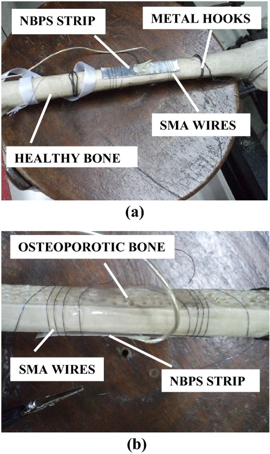
Arrangement for NBPS clamping using SMA wires. a Healthy bone, b osteoporotic bone
Fig. 3.

Complete experimental set up
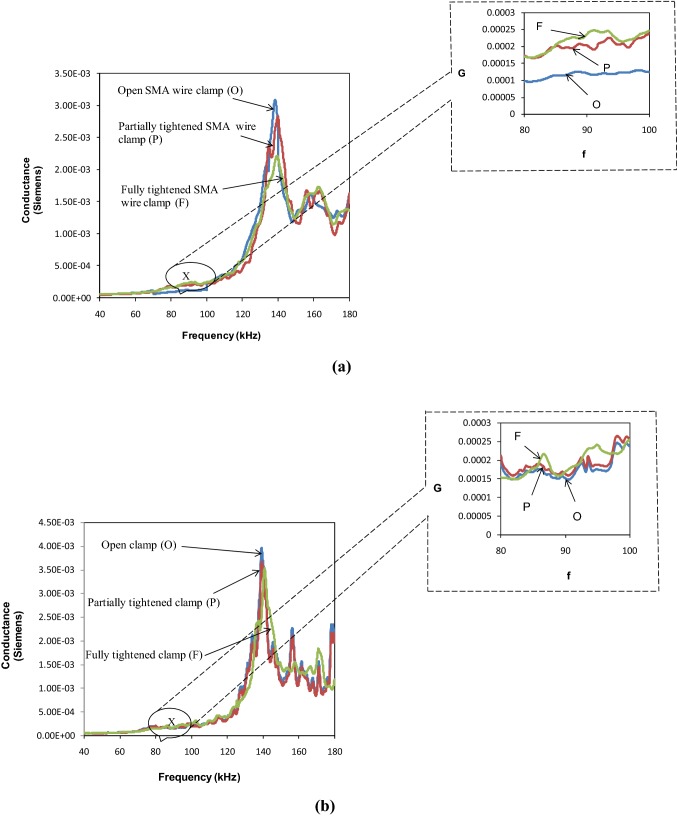
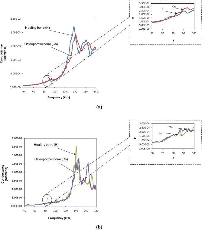
Excellent repeatability for the partially tightened and fully tightened SMA based NBPS configurations is evident from Fig. 4a, b. Figure 5a, b compare the conductance signatures of the SMA based NBPS with the jubilee clamp based NBPS for the three levels of clamp tightening. The figures show similar kind of trend wherein the piezo peaks subside and the structural peaks strengthen as clamping progresses from the open to the partially tightened and finally to the fully tightened NBPS configuration. Figure 6 compares the signatures of the healthy and the osteoporotic bones. From Fig. 6a it is observed that for fully tightened SMA based NBPS configuration, the peak shifts appreciably towards higher frequencies as osteoporotic condition develops. This is consistent with the bond for the jubilee clamp in Fig. 6b. Hence, the SMA based clamping is equally effective as compared to the jubilee clamp based clamping. However, while the jubilee clamp based gripping is tedious and could be bit painful for the subject, the SMA based clamping is instantaneous and can be achieved through electric current. Small time duration involved implies good practical feasibility in real-life conditions. The next section covers the impedance analysis based physiological decay and damage detection of bones.
Fig. 4.
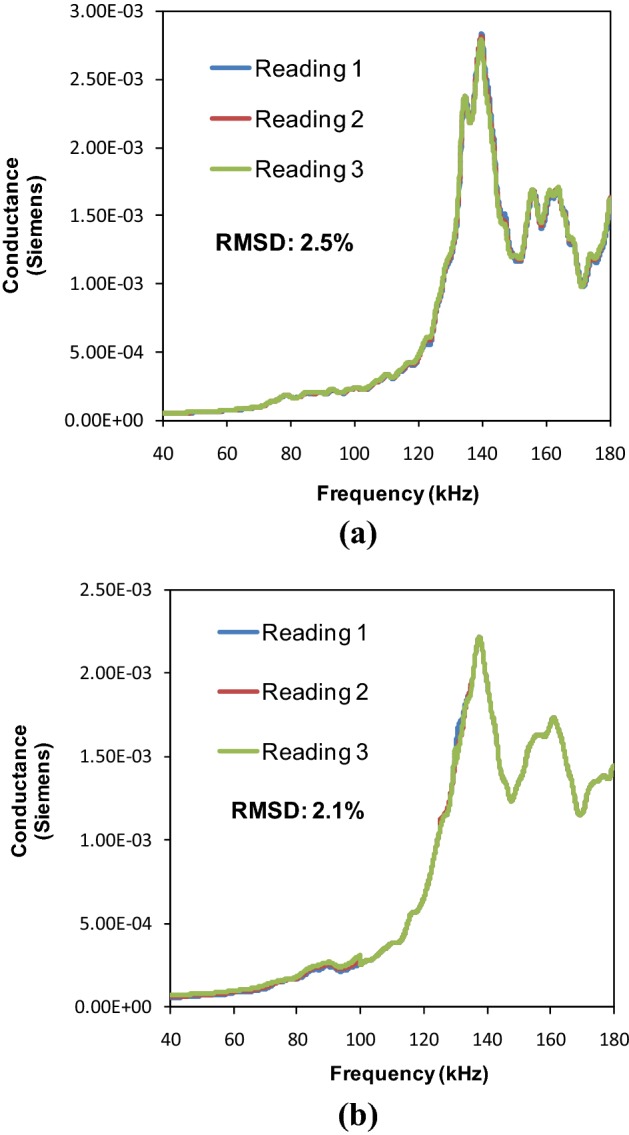
Repeatability of conductance signatures for SMA based NBPS. a Partially tightened condition, b fully tightened condition
Fig. 5.
Comparison of conductance signatures of open, partially tightened and fully tightened NBPS configuration for a SMA based wire clamp b Jubilee clamps
Fig. 6.
Comparison of conductance signatures of healthy and osteoporotic bone for fully tightened NBPS configuration a SMA wire based clamping, b Jubilee clamping
Impedance based bone diagnostics
Electrical and mechanical systems impedance
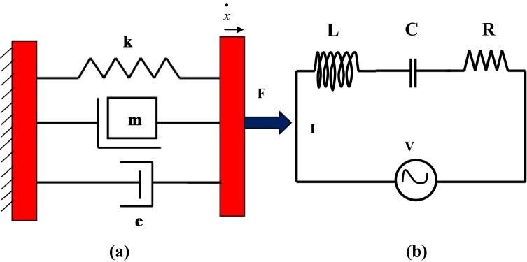
The concept of mechanical impedance is analogous to electrical impedance in electrical circuits [25]. By reducing the differential equations of complex mechanical systems to simple algebraic equations, the impedance approach permits a simplified analysis of complicated mechanical systems [26]. On analysis, it is found that a single degree of freedom (SDOF) spring-mass-damper system is mathematically analogous to a series LCR circuit in the classical electricity as shown in Fig. 7a, b. The instantaneous velocity term is analogous to the current and the mechanical force is analogous to electromotive-force (voltage).
Fig. 7.
a Mechanical system, b Electrical circuit
Consider a dynamic force F at an angular frequency ω applied on a single degree of freedom spring- mass-damper system (Fig. 7a). Let the instantaneous velocity response be
| 3 |
where is the velocity amplitude and ϕ the phase lag of the velocity with respect to the applied force. By simple integration and differentiation of Eq. (3) respectively, the displacement and the acceleration can be determined. Thereafter, forces due to all structural elements including the spring (elastic force Fs), damper (dissipative force Fd) and mass (inertial force Fi) can be determined. Thus
| 4 |
| 5 |
| 6 |
The basic elements viz the mass (m), the spring (k) and the damper (c) can be combined together in a number of different ways (series, parallel or mixture) to evolve complex mechanical systems [27]. Mathematically, analogous behaviour of the parallel mechanical system (Fig. 7a) with series LCR circuit (Fig. 7b) in classical electricity can be observed from Eqs. (4) to (6). The instantaneous velocity () is analogous to the current (I) and the mechanical force is analogous to the potential difference (V) across the LCR circuit. The damper is analogous to the resistor, since damping force is in phase with instantaneous velocity. The mass is analogous to the inductor as the inertial force leads the instantaneous velocity by 90°. Similarly, spring force is analogous to the capacitor, since it lags instantaneous velocity by 90°.
The electrical impedance is analogous to the mechanical impedance, that is
| 7 |
The next section presents the mathematical approach to carry out an impedance-based identification of the experimental bone specimens and employ the same for more rigorous diagnosis of the bone.
Methodology and physical interpretation
In the impedance based structural identification associated with EMI technique [27], both the real and the imaginary parts of the raw complex admittance acquired from the instrumented PZT patch are employed to obtain structure specific parameters. The absolute mechanical impedance is given by where ‘x’ is the real part and ‘y’ the imaginary part of the drive point mechanical impedance of the host structure. Hence, these are the apparent structural parameters at the end of PZT patch. Compared to the stresses and strains, these parameters are more sensitive to structural damages [28, 29]. Applying the principle of active and passive signature decomposition, the mechanical impedance of the host structure can be determined from the admittance signatures of the surface bonded PZT patches [28, 29]. In this section, same procedure has been extended to the PZT patches in NBPS configuration.
The admittance () signatures can be separated into active and passive component as [27]
| 8 |
where is the active component comprising of structural impedance term and is the passive component comprising of only PZT impedance term. can be further broken down into real and imaginary parts expressed as
| 9 |
Passive conductance (GP) and Passive susceptance (BP) can be determined with appreciable accuracy from PZT parameters deduced from the signature of PZT patches in free–free condition prior to bonding on the host structure. It is the active component which is affected by damage and can be deduced by filtering the passive component from the raw signatures, as expressed by
| 10 |
Hence,
| 11 |
and
| 12 |
In complex form, the active component can be expressed as [27]
| 13 |
where l is the half length of the PZT patch, the complex tangent function, Z the complex mechanical impedance of the structure, Za the complex mechanical impedance of the PZT patch, d31 is the piezoelectric strain coefficient of the PZT patch, is the complex Young’s modulus, h is the thickness of the PZT patch, ν is the poisson’s ration, G and B are the raw conductance and susceptance respectively and GA and BA are the active conductance and susceptance respectively. Substituting where η is the mechanical loss factor and T = r+tj into equation and rearranging the various terms, the following expression can be obtained
| 14 |
where the terms P,Q, R and S can be expressed as
| 15 |
| 16 |
Further, substitute Z = x+yj and Za= xa+ yaj where xa is the real part of the mechanical impedance of the PZT patch and ya is the imaginary part of the mechanical impedance of the PZT patch. Upon solving, the real and imaginary components of the EDP structural impedance can be obtained as
| 17 |
| 18 |
The impedance (x, y) can be plotted as functions of frequency for some possible combinations of the basic elements. Based on the closeness of the extracted mechanical impedance, to standard systems, the unknown structure can thus be idealized as an equivalent structure (series or parallel combination of the basic elements), and the equivalent system parameters can thereby be determined [27]. The next section employs the procedure to the NBPS based PZT patch on the experimental bones.
Impedance based identification for experimental bones
Healthy and osteoporotic femurs with jubilee clamps based NBPS configuration
The two femurs, one in healthy state and the other in osteoporotic state (see Fig. 2a, b), were considered to demonstrate the proposed method of impedance-based diagnosis. The osteoporotic bone was designed by the manufacturer in a manner such that holes were drilled on half sectional cut surface of the bone. A close examination of the extracted impedance components in the frequency range of 70-100 kHz for the healthy femur suggested that the system behaviour was similar to a series spring, mass and damper (k–c–m) combination, shown in Fig. 8. For this system, the real (x) and imaginary (y) parts of the mechanical impedance of bones are related to the components k, c and m [27] by
| 19 |
Fig. 8.

Spring, mass and damper series combination representing healthy bone
Figure 9a shows the typical variation of a series k–m–c system and Fig. 9b that of the experimental bone. The similarity between the two suggests that the choice of the series k-m-c system is satisfactory. The frequency at which y crosses the frequency axis is given by
| 20 |
Fig. 9.

Variation of x and y for a standard series k–m–c system, b the experimental bone
Using Eqs. 17, 18 and 19, the system parameters, can be determined, by algebraic operations, as [27]
| 21 |
| 22 |
and
| 23 |
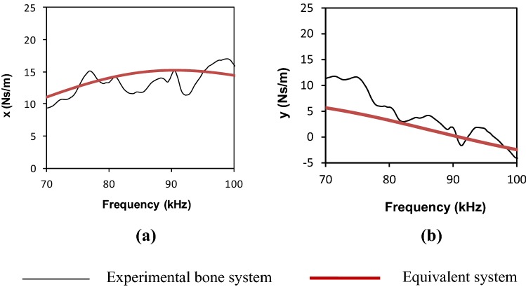
From these equations, for healthy bone, a set of system parameters c = 15.179 Ns/m, k = 7.386 × 10⁶ N/m and m = 2.27 × 10⁻⁵ kg were worked out. Using these parameters, the variation of ‘x’ and ‘y’ (using Eq. 19) produced a pattern shown in Fig. 10. The pattern is compared with the experimental variation of ‘x’ and ‘y’. Reasonably good agreement can be observed between the plots obtained experimentally and those pertaining to the equivalent system implying a good degree of system identification in terms of equivalent parameters k, m and c.
Fig. 10.
Mechanical impedance of healthy bone in 70–100 kHz frequency range using jubilee clamps. a Real part (x) versus frequency, b Imaginary part (y) vs frequency
Similarly, for the osteoporotic bone, a close examination of the extracted impedance components in the frequency range of 75–100 kHz suggested that the system behaviour was similar to a parallel combination of spring and damper in series with a mass, as shown in Fig. 11. For this system [27]
| 24 |
Fig. 11.
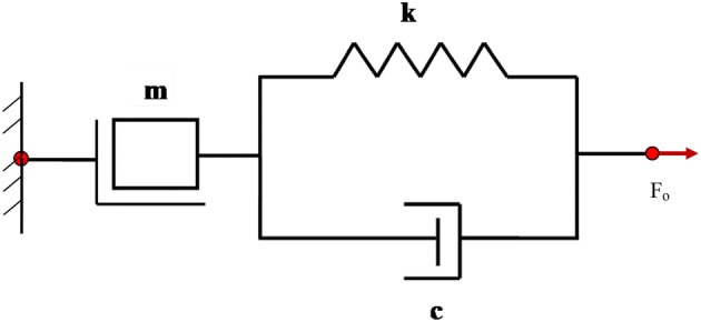
Mass in series with a spring and damper parallel combination representing osteoporotic bone
If x = xo (the peak magnitude) at ω = ωo and x = x1 (somewhat less than peak magnitude) at
ω = ω1, the system parameters are given by solving the following system of equations
| 25 |
| 26 |
| 27 |
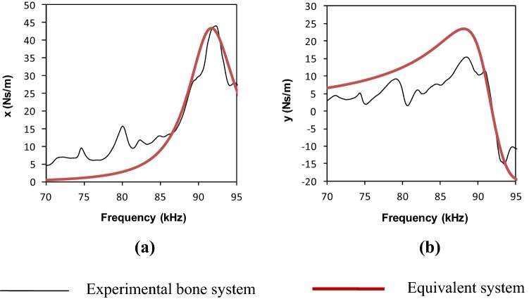
These equations resulted in a set of system parameters c = 0.3011 Ns/m, k = 2.077 × 10⁶ N/m and m = 0.6292 × 10⁻⁵ kg for the osteoporotic bone. Use of these parameters in Eq. (24) produced an impedance pattern as shown in Fig. 12. Again, reasonably good agreement can be observed between the plots obtained experimentally and those pertaining to the equivalent system. Table 1 shows the percentage change in the dynamic properties of bone with osteoporotic degradation using jubilee clamp based NBPS configuration. It is to be noted that the impedance parameters are extracted from the raw conductance signatures and then they are compared with the standard models [26]. Thus these models reflect the dynamic characteristics of the structure and are not based on author’s assumption. Thus different models represent the change in any structure/bone after damage.
Fig. 12.
Mechanical impedance of osteoporotic bone in 70–95 kHz frequency range using jubilee clamps. a Real part (x) vs frequency, b imaginary part (y) vs frequency
Table 1.
System parameters for healthy and osteoporotic bone using jubilee clamps
| System parameters | Healthy bone | Osteoporotic bone | % Change |
|---|---|---|---|
| c (Ns/m) | 15.179 | 0.3011 | 98 |
| m (kg) | 2.27 × 10⁻⁵ | 0.6292 × 10⁻⁵ | 72 |
| k (N/m) | 7.386 × 10⁶ | 2.077 × 10⁶ | 72 |
Healthy and osteoporotic femurs with SMA wires based NBPS configuration
A close examination of the extracted impedance components in the frequency range of 100–120 kHz for the healthy femur suggested that the system behaviour was similar as in the case of jubilee clamps which was analogous to a series spring, mass and damper (k–c–m) combination. For the healthy bone, a set of system parameters c = 14.179 Ns/m, k = 6.384 × 10⁶ N/m and m = 1.87 × 10⁻⁵ kg were worked out. Using these parameters, the variation of ‘x’ and ‘y’ produced a pattern shown in Fig. 13. Again, reasonably good agreement can be observed between the plots obtained experimentally and those pertaining to the equivalent system implying a good degree of system identification.
Fig. 13.
Mechanical impedance of healthy bone in 100-120 kHz frequency range using SMA based clamp. a Real part (x) vs frequency, b imaginary part (y) vs frequency
Again a close examination of the extracted impedance components in the frequency range of 100-120 kHz for the osteoporotic femur suggested that the system behaviour was similar as in the case of jubilee clamps which was analogous to a parallel combination of spring and damper in series with mass. For the osteoporotic bone, a set of system parameters c = 0.2879 Ns/m, k = 1.346 × 10⁶ N/m and m = 0.4582 × 10⁻⁵ kg for the osteoporotic bone. Using these parameters, the variation of ‘x’ and ‘y’ produced a pattern shown in Fig. 14. Again, reasonably good agreement can be observed between the plots obtained experimentally and those pertaining to the equivalent system. Table 2 shows the percentage change in the dynamic properties of bone with osteoporotic degradation using SMA wires based NBPS configuration. All the three properties i.e. k, m and c reduce drastically with transition from healthy to osteoporotic bone. The percentage reduction is quite high because for simulating osteoporosis effect, a sectional cut was already given to the bone which reduced its mass. The comparisons of Tables 1 and 2 shows that the SMA clamped NBPS system is at par with the jubilee clamp based NBPS system as far as bone diagnosis is concerned.
Fig. 14.
Mechanical impedance of osteoporotic bone in 100–120 kHz frequency range using SMA based clamps. a Real part (x) vs frequency, b imaginary part (y) vs frequency
Table 2.
System parameters for healthy and osteoporotic bone using SMA wire based clamps
| System parameters | Healthy bone | Osteoporotic bone | % Change |
|---|---|---|---|
| c (Ns/m) | 14.179 | 0.2879 | 98 |
| m (kg) | 1.87 × 10⁻⁵ | 0.4582 × 10⁻⁵ | 75.4 |
| k (N/m) | 6.384 × 10⁶ | 1.346 × 10⁶ | 79 |
From comparison of the values of the identified system parameters for femurs with jubilee clamp based NBPS, it can be ascertained that due to osteoporosis, the piezo identified stiffness and mass both are reduced by 72% and the damping is reduced by 98%. This indicates a high degree of structural degradation resulting from experimentally simulated osteoporosis as well as the half sectional cut given by the manufacturer with holes drilled on the bone surface to induce osteoporosis, latter effect being the major contributor. The high severity can also be recognized by the fact that the identified equivalent system underwent drastic change, transforming from series k–m–c system (Fig. 8) to a parallel k–c system in series with m (Fig. 11). Similarly with SMA clamping, the stiffness gets reduced by 79%, mass by 75.4% and damping is reduced by 98%, thereby indicating that SMA clamping is equally effective as jubilee clamping.
Quantification of NBPS clamping
Using Eqs. (13) to (18), the absolute structural mechanical impedance can be calculated from the conductance and susceptance signatures for both the NBPS (ZNBPS) and the DBPS (ZDBPS) configurations. From analysis, the average of the values of impedance at each frequency in the given range gives a relation, that is, ZDBPS= α ZNBPS where α is the clamping factor. Average value of α came out to be 0.648. Thus, we get a modified admittance equation for NBPS configuration which is given by
| 28 |
Conclusions
This paper has further extended the proof-of-concept NBPS configuration employing jubilee clamps to fully autonomous SMA based clamping, which can be activated by means of a battery induced current. It is almost instantaneous and reversible. These results also indicate that for the particular case of femurs, fully tightened clamping of NBPS configuration employing SMA wires is as effective as mechanical jubilee clamping for the same level of tightening. Also, there are less chances of PZT patch damage, since the bending effect in the NBPS aluminium strip has significantly reduced. Thus SMA wires can prove to be a futuristic clamping tool for NBPS which ensures better mechanical interaction of the NBPS with the structure. In the present investigation, the parameters corresponded to different bone specimens instrumented with different PZT patches. All previous studies, on the other hand, monitored degradation of same component using same PZT patch. In addition, this is the first ever extraction of system parameters from non-bonded configuration. The study provides a parametric quantification of bone degradation. Presently, only proof-of-concept demonstration is provided in this paper. This approach can be further employed to develop empirical correlation between the equivalent parameters with the extent of osteoporosis after experimental analysis of large number of subjects.
Compliance with ethical standards
Conflict of interest
All authors declares that they have no conflict of interest.
Ethical approval
This article does not contain any studies with human participants or animals performed by any of the authors.
Footnotes
Shashank Srivastava: Formerly Research Scholar, Indian Institute of Technology, New Delhi.
Publisher's Note
Springer Nature remains neutral with regard to jurisdictional claims in published maps and institutional affiliations.
Contributor Information
Shashank Srivastava, Email: shashank.iet22@gmail.com.
Suresh Bhalla, Email: sbhalla@civil.iitd.ac.in.
Alok Madan, Email: madan@civil.iitd.ac.in.
References
- 1.Kim H, Lee J, Kim J. Electromyography-signal-based muscle fatigue assessment for knee rehabilitation monitoring systems. Biomed Eng Lett. 2018;8(4):345–353. doi: 10.1007/s13534-018-0078-z. [DOI] [PMC free article] [PubMed] [Google Scholar]
- 2.Dong B, Biswas S. Wearable sensing for liquid intake monitoring via apnea detection in breathing signals. Biomed Eng Lett. 2014;4(4):378–387. doi: 10.1007/s13534-014-0149-8. [DOI] [Google Scholar]
- 3.Lim YG, Hong KH, Kim KK, Shin JH, Lee SM, Chung GS, Baek HJ, Jeong DU, Park KS. Monitoring physiological signals using non-intrusive sensors installed in daily life equipment. Biomed Eng Lett. 2011;1(1):11–20. doi: 10.1007/s13534-011-0012-0. [DOI] [Google Scholar]
- 4.Bhalla S, Bajaj S. Bone characterization using piezo-transducers as bio-medical sensors. Strain. 2008;44(6):475–478. doi: 10.1111/j.1475-1305.2007.00397.x. [DOI] [Google Scholar]
- 5.Bhalla S, Suresh R. Condition monitoring of bones using piezo-transducers. Meccanica. 2013;48(9):2233–2244. doi: 10.1007/s11012-013-9740-9. [DOI] [Google Scholar]
- 6.Erickson GM, Catanese J, III, Keaveny TM. Evolution of the biomechanical material properties of the femur. Anat Rec. 2002;268:115–124. doi: 10.1002/ar.20929. [DOI] [PubMed] [Google Scholar]
- 7.Ritchie RO, Nalla RK, Kruzie JJ. Fracture and ageing in bone: toughness and structural characterization. Strain. 2006;42:225–232. doi: 10.1111/j.1475-1305.2006.00282.x. [DOI] [Google Scholar]
- 8.Boemio G, Rizzo P, Nardo LD. Assessment of dental implant stability by means of the electromechanical impedance method. Smart Mater Struct. 2011;20(4):11. doi: 10.1016/j/jbiomech.2015.05.020. [DOI] [Google Scholar]
- 9.Ribolla ELM, Rizzo P, Gulizzi V. On the use of the electromechanical impedance technique for the assessment of dental implant stability: modeling and experimentation. J Intell Mater Syst Struct. 2014;10:1–15. doi: 10.1177/1045389x14554129. [DOI] [Google Scholar]
- 10.Srivastava S, Bhalla S, Madan A. Assessment of human bones encompassing physiological decay and damage using piezo sensors in non-bonded configuration. J Intell Mater Syst Struct. 2017;28(14):1977–1992. doi: 10.1177/1045389x16672570. [DOI] [Google Scholar]
- 11.Buehler WJ, Gifrich JV, Wiley RC. Effect of low temperature phase changes on the mechanical properties of alloys near composition TiNi. J Appl Phys. 1963;34(5):1475–1477. doi: 10.1063/1.1729603. [DOI] [Google Scholar]
- 12.Buehler WJ, Wiley RC, Wang FE. Nickel based alloys. US Patent 3.1965, 174 851.
- 13.Stoeckel D, Borden T. Actuation and fastening with shape memory alloys in the automotive industry. Metall Wissenschaft + Technik Juli. 1992;7:668–672. [Google Scholar]
- 14.Srivastava A, Verma Y, Rao KD, Gupta PK. Determination of elastic properties of resected human breast tissue samples using optical coherence tomographic elastography. Strain. 2011;47(1):75–87. doi: 10.1111/j.1475-1305.2009.00627.x. [DOI] [Google Scholar]
- 15.Talakokula V, Bhalla S, Gupta A. Corrosion assessment of RC structures based on equivalent structural parameters using EMI technique. J Intell Mater Syst Struct. 2014;25(4):484–500. doi: 10.1177/1045389X13498317. [DOI] [Google Scholar]
- 16.Li W, Liu T, Zou D, Wang J, Yi TH. PZT based smart corrosion coupon using electromechanical impedance. Mech Syst Signal Process. 2019;129:455–469. doi: 10.1016/j.ymssp.2019.04.049. [DOI] [Google Scholar]
- 17.Talakokula V, Bhalla S, Gupta A. Monitoring early hydration of reinforced concrete structures using structural parameters identified by piezo sensors via electromechanical impedance technique. Mech Syst Signal Process. 2018;99(1):129–141. doi: 10.1016/j.ymssp.2017.05.042. [DOI] [Google Scholar]
- 18.Bhalla S, Vittal APR, Veljkovic M. Piezo-impedance transducers for residual fatigue life assessment of bolted steel joints. J Struct Health Monit. 2012;11(6):733–750. doi: 10.1177/1475921712458708. [DOI] [Google Scholar]
- 19.Lim YY, Tang ZS, Smith ST. Piezoelectric based monitoring of the curing of structural adhesives: a novel experimental study. Smart Mater Struct. 2018;28(1):015016. doi: 10.1088/1361-665X/aaeea4. [DOI] [Google Scholar]
- 20.Wandowski T, Malinowski PH, Ostachowicz WM. Temperature and damage influence on electromechanical impedance method used for carbon fibre-reinforced polymer panels. J Intell Mater Syst Struct. 2017;28(6):782–798. doi: 10.1177/1045389X16657423. [DOI] [Google Scholar]
- 21.Lu X, Lim YY, Soh CK. Investigating the performance of ‘Smart Probe’ based indirect EMI technique for strength development monitoring of cementitious materials—modelling and parametric study. Constr Build Mater. 2018;172:134–152. doi: 10.1016/j.conbuildmat.2018.03.222. [DOI] [Google Scholar]
- 22.Lu X, Lim YY, Soh CK. A novel electro-mechanical impedance based model for strength development monitoring of cementitious materials. Struct Health Monit. 2018;17(4):902–918. doi: 10.1177/1475921717725028. [DOI] [Google Scholar]
- 23.Srivastava S, Bhalla S, Madan A, Gupta A. Numerical evaluation of non-bonded piezo sensor for biomedical diagnostics using electromechanical impedance technique. Int J Numer Methods Biomed Eng. 2019;35(2):e3160. doi: 10.1002/cnm.3160. [DOI] [PubMed] [Google Scholar]
- 24.Furst SJ, Crews JH, Seelecke S. Stress, strain and resistance behaviour of two opposing shape memory alloy actuator wires for resistance-based self-sensing applications. J Intell Mater Syst Struct. 2013;24(16):1–18. doi: 10.1177/1045389X13486715. [DOI] [Google Scholar]
- 25.Halliday D, Resnick R, Walker J. Fundamentals of physics. 6. New York: Wiley; 2001. pp. 768–800. [Google Scholar]
- 26.Hixon EL. Mechanical impedance, shock and vibration handbook. In Harris CM, editors, 3rd ed. New York: McGraw Hill Book Co.; 1988:10.1–10.46.
- 27.Bhalla S, Moharana S, Talokokula V, Kaur N. Piezoelectric materials applications in SHM, energy harvesting and bio-mechanics. India: Athena Academic and Wiley; 2017. [Google Scholar]
- 28.Bhalla S, Soh CK. Structural health monitoring by piezo-impedance transducers: part I modeling. J Aerosp Eng ASCE. 2004;17(4):154–165. doi: 10.1061/(ASCE)0893-1321(2004)17:4(154). [DOI] [Google Scholar]
- 29.Bhalla S, Soh CK. Structural health monitoring by piezo-impedance transducers: part II applications. J Aerosp Eng ASCE. 2004;17(4):166–171. doi: 10.1061/(ASCE)0893-1321(2004)17:4(166). [DOI] [Google Scholar]


