

Abstract

A novel nitrile-/cyano-free ionic liquid was synthesized and carbonized under two different carbonization methods in the presence of ZnCl2 as a catalyst to afford N-doped carbon materials. It was found that the carbonization condition could affect the nature and textural properties of the resulting carbon. In the following, ionic liquid-derived carbon was hybridized with naturally occurring halloysite nanotubes via two procedures, that is, hydrothermal treatment of halloysite and as-prepared carbon and carbonization of ionic liquid in the presence of halloysite. The two novel nanocomposites were then used for stabilizing Pd nanoparticles. Examining the structures and catalytic activities of the resulting catalysts for the hydrogenation of nitroarenes in aqueous media showed that the carbonization procedure and hybridization method could affect the structure and the catalytic activity of the catalysts and hydrothermal approach, in which the structure of halloysite is preserved, leading to the catalyst with superior catalytic activity.
Introduction
Considering the wide range of applications of heteroatom-doped carbon materials,1−5 many attempts have been made to develop efficient methods for their preparation.6,7 In this context, two main methodologies, that is, posttreatment of carbon materials with suitable gases and carbonization of heteroatom-containing precursors, have been developed.8 In contrast, homogeneous incorporation of nitrogen with a controlled chemistry is achieved by the latter approach, and as a part of these methodologies, a wide range of precursors such as pyridine,9 acetonitrile,10 polyacrylonitrile,11 or others12 have been used. However, carbonization of most of organic compounds generates completely gaseous products under the high-temperature procedure, so currently available precursors are rather limited. Polymer-related procedures, on the other hand, are multistep and time-consuming. These deficiencies have led scientists to focus on a new category of compounds such as carbon precursors.
Ionic liquids, ILs, are organic salts composed of heteroatom-containing cations as well as anions.13 Conventional ILs have low vapor pressure and are not proper for carbonization, while nitrile-/cyano-containing ILs can tolerate harsh condition of carbonization to furnish heteroatom-doped carbon materials.14−16 However, the synthesis of these compounds is time-consuming and costly. Moreover, the textural properties of the final carbon are not mostly satisfying and need some modification. Hence, other methodologies such as carbonization of confined conventional ILs and use of template and structural guides17,18 have been developed.15,16 However, each approach has its own drawbacks.
The biocompatible and nontoxic nature of naturally occurring halloysite nanoclay, Hal, as well as its availability expanded its applications in many scientific and industrial uses such as composite and material science, catalysis, cleaning, separation, smart delivery systems, and so forth.18−31 Considering the increasing use of Hal, it can be concluded that this natural clay is focused remarkably and can be considered as a potential alternative for many synthetic inorganic compounds such as mesoporous silica or conventional minerals. As Hal possesses a tubular morphology with tunable surface area and attractive textural and mechanical properties,18,21,22,32,33 its utility as a catalyst support has received much attention. Hal in its individual or functionalized form or in combination with other compounds can be used for the catalytic purposes.20,34,35
Using hydrogen gas as a reducing agent for transforming unsaturated chemicals to the saturated counterparts is economically and environmentally interesting process. To promote hydrogenation reactions such as converting nitro group to amine functionality, use of the catalyst is imperative. In this context, mostly, precious metals are used, which make the process costly. To circumvent this limitation, supporting catalysts on efficient supports that do not deactivate the catalytic sites and result in heterogeneous and recyclable catalysts are proposed.36−40
In continuation of our study on the catalytic composites,41 recently, we disclosed the outstanding performance of Hal–carbon composites as catalyst supports.42,43 Our results confirmed the synergism between Hal and carbon that resulted in the catalysts with superior catalytic performances compared to the individual components. Considering these promising results and in the search for novel Hal–C composite systems, herein we present a novel catalyst that was obtained through immobilization of Pd nanoparticles on a composite prepared from the hydrothermal treatment of Hal with a novel IL-derived N-doped porous carbon. Notably, to synthesize the N-doped carbon material, a new cyano-/nitrile-free IL (TCT-IMI) was designed and synthesized from the reaction of cyanuric chloride and 1-methyl imidazole through a simple protocol (Figure 1). In this study, use of ZnCl2 as a catalyst was presented for efficient carbonization of IL in the absence of any structural guide. This approach not only obviates the need for confinement of ILs or using costly nitrile-containing ILs but also presents a cost-effective and simple method for preparing N-doped porous carbons. To study the effect of carbonization temperature on the nature of the resulting carbon materials, two samples carbonized under two different carbonization methods were prepared, and their structural features were compared. Moreover, to study the effect of method of hybridization of Hal and IL-derived carbon on the catalytic activity of the final catalyst, two protocols, carbonization of IL in the presence of Hal and hydrothermal treatment of Hal in the presence of IL-derived carbon, were examined, and the structures of two composites as well as their catalytic performances were compared for the hydrogenation of nitroarenes.
Figure 1.

Schematic procedure for the synthesis of CIL-1, CIL-2, Pd@Hal–CIL-2(1:2)-C, and Pd@Hal–CIL-2(1:2)-HT.
Results and Discussion
To prepare the hybrid of Hal and IL-derived carbon, a novel task-specific cyano-/nitrile-free IL was first synthesized (see the Experimental Section). The formation of TCT-IMI was confirmed by recording its 1H NMR and 13C NMR spectra as well as thermogravimetric analysis (TGA). The TGA of the IL showed a weight loss below 150 °C that is due to the loss of water and a weight loss at about 250 °C that can be assigned to the degradation of IL (Figure S1).
The NMR spectroscopy has provided sufficient information on the structure of TCT-IMI and confirmed the accuracy of the structure. 1H NMR and 13C NMR spectroscopies (Figure S2) revealed the characteristic signals of four hydrogen types and five carbon types in the synthesized IL structure, respectively. The symmetry in the TCT-IMI structure has led to the adaptation of the hydrogen signals in the imidazolium rings. The detailed NMR data are as follows:
1H NMR (400 MHz, DMSO): δ 2.5 (s, 3H, −CH3), 7.64 (s, 3H, −CH−), 7.69 (s, 3H, −CH−), 9.18 (s, 3H, −CH−); 13C NMR (100 MHz, DMSO): δ 35.8, 120.1, 123.5, 135.9, 150.3.
In the following, TCT-IMI was used as a carbon precursor to prepare a carbon material, CIL. To study the effect of carbonization condition on the nature of the resulting carbon material, two different thermal processes were used for the carbonization (see the Experimental Section for the preparation of CIL-1 and CIL-2). The characterizations of the resulting carbons, CIL-1 and CIL-2, are as follows:
CIL-1 was characterized by applying Raman, Fourier transform infrared (FTIR), CHN, TGA, X-ray diffraction (XRD), and Brunauer–Emmett–Teller (BET) techniques (Figure 2). As depicted in Figure 2A, the FTIR spectrum of CIL-1 confirmed that the formed carbon material possessed some functional groups. In detail, the characteristic bands at 1546 and 1627 cm–1 can be assigned to the −C=C and −C=N functionalities, respectively, the band at 3423 cm–1 can be indicative of −OH groups, and the observed band at 2850 cm–1 can be representative of the −CH2 functionality. The thermogram of CIL-1 (Figure 2B) indicated the high thermal stability of this sample, confirming the successful carbonization. The XRD pattern of CIL-1 (Figure 2C) exhibited a broad band at 2θ = 15–23° as well as two sharp bands at 2θ = 26° that can indicate the diamond–lonsdaleite system.44 The Raman spectrum of CIL-1 (Figure 2D) indicated that the nature of the formed carbon is diamond-like amorphous carbon.45,46 According to the literature,47,48 the amorphous nature of CIL-1 can be attributed to the high content of nitrogen atoms in the carbon lattice that led to the amorphization of the graphitic network. To confirm this issue, the CHN analysis was performed. According to the CHN analysis, the percentages of H, C, and N in CIL-1 were calculated to be 1.61, 62.21, and 10.96%, respectively. Finally, the N2 adsorption–desorption isotherm of CIL-1 showed type II isotherm with a specific surface area of 41 m2 g–1.
Figure 2.

FTIR spectrum (A), TGA (B), XRD pattern (C), and Raman spectrum (D) of CIL-1.
Similar to CIL-1, the formation of CIL-2 was verified by using FTIR, CHN, BET, Raman, TGA, and XRD (Figure 3). As depicted in Figure 3A, CIL-2 exhibited the characteristic bands at 3451, 2952, 1729, and 1658 cm–1 that can be attributed to the −OH, −CH2, −C=N, and −C=C functionalities, respectively. Similar to CIL-1, the thermogram of CIL-2 (Figure 3D) confirmed the successful carbonization and high thermal stability of this sample. The XRD pattern as well as the Raman spectrum of CIL-2 (Figure 3B,C) was distinguished from those of CIL-1. As shown, the Raman spectrum of CIL-2 exhibited two bands at 1343 and 1584 cm–1 that are indicative of the graphitic nature of CIL-2. The XRD pattern of CIL-2 (Figure 4C) showed a band at 2θ = 25° that confirms the graphitic nature of CIL-2. Considering the previous reports,49 it can be assumed that the formation of a graphitic carbon initiated at an early step of carbonization and the low-temperature thermal decomposition of the IL controls whether or not the final carbon generated at the elevated temperature will be graphitic. Consequently, CIL-2 with a longer carbonization process at a lower temperature has a more graphitic structure.
Figure 3.

FTIR spectrum (A), XRD pattern (B), Raman spectrum (C), and TGA (D) of CIL-2.
Figure 4.

FTIR spectra (A), TGA (B), and XRD patterns (C) of Pd@Hal–CIL-2(1:2)-C and pristine Hal.
Notably, the specific surface area of CIL-2 was estimated to be 568 m2 g–1 that is far higher than that of CIL-1. According to the CHN analysis, the percentages of H, C, and N in CIL-2 were calculated to be 1.32, 68.41, and 7.87%, respectively. Comparing the CHN results of CIL-1 and CIL-2, it can be concluded that using a longer and harsher carbonization protocol led to the decrease of the N content. This observation is in good agreement with the previous reports.50
The characterization of two carbon materials, CIL-1 and CIL-2, indicated that the carbonization condition affects the properties (specific surface area, nitrogen content, etc.) of the resulting carbon. Interestingly, the catalytic activity of the catalysts prepared via Pd immobilization of these two carbon materials also showed different catalytic activities, and Pd@CIL-2 was more effective than Pd@CIL-1 (vide infra). Considering the superior performance of CIL-2 for the catalytic purpose and in an attempt to improve its activity, CIL-2 was hybridized with Hal. For this purpose, two different hybridization processes were examined. First, TCT-IMI was carbonized in the presence of Hal to generate Hal–CIL-2(1:2)-C. The second procedure was the hydrothermal treatment of Hal with CIL-2 to afford Hal–CIL-2(1:2)-HT. The two hybrid systems were then used as Pd supports. The resulting catalysts, Pd@Hal–CIL-2(1:2)-HT and Pd@Hal–CIL-2(1:2)-C, were then characterized.
The structure of Pd@Hal–CIL-2(1:2)-C was verified by FTIR, XRD, TGA, and BET. Moreover, to study the effect of the incorporation of CIL-2 on the structure of Hal, all the above-mentioned analyses were compared with those of pristine Hal (Figure 4). As depicted in Figure 4A, the FTIR spectra of Pd@Hal–CIL-2(1:2)-C and Hal are distinguishable. More precisely, in the FTIR spectrum of Hal, the characteristic bands at 1107 cm–1 that is indicative of Si–O stretching, 3696 and 3624 cm–1 that are due to the internal hydroxyl functionality of Hal, and 580 cm–1 that represents Al–O–Si vibration can be observed, while in the FTIR spectrum of Pd@Hal–CIL-2(1:2)-C, some Hal characteristic bands disappeared and the characteristic bands of CIL-2 can be detected. In more details, a short characteristic band at 1107 cm–1 (Si–O stretching) can be observed in the FTIR spectrum of Pd@Hal–CIL-2(1:2)-C. According to the literature, thermal treatment of Hal that can affect the structure of Hal can justify this observation.51 The Hal thermogram (Figure 5B) showed two weight losses at ∼120 and 540 °C that are due to the loss of water in the Hal framework and dehydroxylation of the Hal matrix, respectively.52,53 Pd@Hal–CIL-2(1:2)-C that contained CIL-2 with high thermal stability however showed higher thermal stability compared to the pristine Hal. In Figure 4C, comparison of the XRD pattern of Hal and Pd@Hal–CIL-2(1:2)-C showed that the two samples exhibited different XRD patterns. More precisely, the XRD pattern of Pd@Hal–CIL-2(1:2)-C does not contain the characteristic bands of Hal (2θ = 12.4, 18.8, 20.5, 25.2, 36.7, 39.0, 56.3, and 62.5°) (JCPDS no. 29-1487, labeled as *)54,55 but shows a broad 2θ = 20–30° that is representative of amorphous silica. This observation indicates that thermal treatment led to the destruction of the Hal structure. This observation is in good agreement with the literature,51,56 which indicated that under carbonization condition Hal tubes can be transferred to silica nanoparticles. In the XRD pattern of Pd@Hal–CIL-2(1:2)-C, the characteristic bands of CIL-2 and Pd nanoparticles (at 2θ = 40, 46.6, 68.4, 82.4, and 87°, JCPDS, card no. 46-1043, labeled as “o”) can also be observed. The BET analysis of Pd@Hal–CIL-2(1:2)-C showed that the specific surface area of this sample was 436 m2 g–1. This value is higher than that of Hal (51 m2 g–1) and lower than that of CIL-2 (568 m2 g–1). It is believed that transformation of Hal nanotubes to amorphous silica upon harsh carbonization condition can block some of the pores of CIL-2 and resulted in lower specific surface area compared to that of CIL-2.
Figure 5.

FTIR spectra of Pd@Hal–CIL-2(1:2)-HT and pristine Hal.
The next sample characterized was Pd@Hal–CIL-2(1:2)-HT that was prepared under hydrothermal condition. First, the FTIR spectrum of this sample was recorded (Figure 5). Similar to Pd@Hal–CIL-2(1:2)-C, the FTIR spectrum of Pd@Hal–CIL-2(1:2)-HT was compared with that of Hal. As depicted, the FTIR spectrum of Pd@Hal–CIL-2(1:2)-HT exhibited the characteristic bands of CIL-2. Similar to the previous sample, the Hal characteristic bands are less pronounced in Pd@Hal–CIL-2(1:2)-HT.
In Figure 6, the XRD pattern of Pd@Hal–CIL-2(1:2)-HT is compared with that of pristine Hal. In the Pd@Hal–CIL-2(1:2)-C sample, the Hal structure collapsed under harsh carbonization condition and no Hal bands were observed, whereas in the Pd@Hal–CIL-2(1:2)-HT XRD pattern, the Hal characteristic bands can be detected. This observation confirmed that hydrothermal treatment did not destruct the Hal structure. Apart from Hal bands, the characteristic bands of CIL-2 and Pd nanoparticles are also observable.
Figure 6.

XRD patterns of Pd@Hal–CIL-2(1:2)-HT and pristine Hal.
In Figure 7, the TGA thermograms of pristine Hal as well as Pd@Hal–CIL-2(1:2)-HT are depicted. Comparing the two thermograms, it can be concluded that the latter exhibited higher thermal stability that can be attributed to the incorporation of CIL-2 with high thermal stability.
Figure 7.

TGAs of pristine Hal and Pd@Hal–CIL-2(1:2)-HT.
Pd@Hal–CIL-2(1:2)-HT was further characterized via BET and ICP. The ICP analysis of Pd@Hal–CIL-2(1:2)-HT revealed that the loading of Pd was low (0.01 mmol g–1). The BET analysis of Pd@Hal–CIL-2(1:2)-HT showed that the specific surface area of this sample was 740 m2 g–1 that was higher than that of CIL-2. It is postulated that incorporation of hollow tubes of Hal in combination with CIL-2 can justify this observation.
Finally, to investigate the morphology of Pd@Hal–CIL-2(1:2)-HT, transmission electron microscopy (TEM) images of the catalyst were recorded. In Figure 8, one of the TEM images of the catalyst is depicted. As shown, Hal nanotubes are observable, confirming that incorporation of IL-derived carbon did not result in the collapse of the Hal structure (this was also confirmed via XRD analysis). However, in some parts, thickening of the tubes and their coverage by fine IL-derived carbon can be seen. On the other hand, fine Pd nanoparticles (small black spots) with an average diameter of 3 ± 1.0 nm and homogeneous dispersion on the support can be detected, indicating that Hal–CIL-2(1:2)-HT could effectively prevent the aggregation of Pd nanoparticles.
Figure 8.

TEM image of Pd@Hal–CIL-2(1:2)-HT.
To investigate the catalytic activity of the palladated Hal–carbon composite and to study the effect of preparation condition on the catalytic activity of the resulting catalytic composite, hydrogenation of nitroarenes was selected as a model catalytic reaction. To start the catalytic experiments, hydrogenation of nitrobenzene was performed in the absence of any catalyst to confirm the necessity of a catalyst for this reaction (Table 1, entry 1). As shown, no aniline was collected without the use of the catalyst. Next, the catalytic activity of Pd@Hal was investigated for this model reaction (Table 1, entry 2) under optimum reaction condition (use of water as the solvent and catalyst 1 wt %). As tabulated, the efficiency of Pd@Hal was low, and only 30% aniline was achieved after 1 h. This result indicated that Hal in its individual form is not an efficient support. According to the literature, this can be attributed to the weak interaction of Hal and Pd.57 In the following, the catalytic activity of Pd@CIL was investigated. As shown, two carbons, CIL-1 and CIL-2, prepared via two different carbonization protocols and possessed different natures, showed different catalytic activities (Table 1, entries 3 and 4), and Pd@CIL-2 resulted in superior catalytic activity. This result can be attributed to the higher specific surface area of CIL-2 (see the BET results) that led to uniform distribution of Pd nanoparticles.58,59 Moreover, the measurement of the Pd loading of two catalysts, that is, Pd@CIL-1 and Pd@CIL-2, showed that the Pd loading of the latter (0.41 mmol g–1) was almost 2 times the former.
Table 1. Comparison of Catalyst Systems in the Hydrogenation of Nitrobenzene.
| entry | catalysta | yield (%)b |
|---|---|---|
| 1 | 0 | |
| 2 | Pd@Hal | 30 |
| 3 | Pd@CIL-1 | 30 |
| 4 | Pd@CIL-2 | 45 |
| 5 | Pd@Hal–CIL-2(1:1)-HT | 50 |
| 6 | Pd@Hal–CIL-2(2:1)-HT | 50 |
| 7 | Pd@Hal–CIL-2(1:2)-HT | 100 |
| 8 | Pd@Hal–CIL-2(1:2)-C | 90 |
Reaction condition: Nitrobenzene (1 mmol), catalyst (1 wt %), H2O (3 mL), H2 (1 bar) at r.t. in 1 h.
Isolated yields.
Having the best CIL in hand, the composite of Hal with CIL-2 was prepared, and its catalytic activity was investigated. In this line, the effects of two factors, that is, the ratio of Hal/CIL-2 and the method of preparation of the nanocomposite on the catalytic activity of the final catalyst, were examined. The effect of the ratio of Hal/CIL-2 was investigated via comparison of the catalytic activities of three control catalysts with different Hal/CIL-2 ratios (Table 1, entries 5–7). As depicted, the 1:2 ratio of Hal/CIL-2 led to the best catalytic activity. To shed more light on this observation, the TGAs of all three samples were carried out, and the content of CIL was calculated in all samples. The results confirmed that in Pd@Hal–CIL-2(1:2), the content of C was higher than that of other two samples, indicating that CIL can contribute to the catalysis. This effect can be justified by the capability of N-doped carbon for the anchoring of Pd nanoparticles. In other words, it can be observed that in Pd@Hal–CIL-2(1:2) with more CIL-2, the nitrogen functionalities in the structure of CIL-2 can more effectively interact with Pd nanoparticles through electrostatic interactions. This result was further confirmed by the ICP analysis that indicated higher Pd loading of Pd@Hal–CIL-2(1:2) compared to that of the other two samples.
To elucidate the effect of the preparation method on the catalytic activity, two samples, Pd@Hal–CIL-2(1:2)-HT that was prepared through the hydrothermal treatment of Hal and CIL-2 and Pd@Hal–CIL-2(1:2)-C that was synthesized by the carbonization of IL in the presence of Hal, were compared in the hydrogenation of nitrobenzene (Table 1, entries 7 and 8). As demonstrated, the sample prepared via hydrothermal treatment of as-prepared CIL-2 with Hal showed a higher catalytic activity. The lower catalytic activity of Pd@Hal–CIL-2(1:2)-C can be attributed to the destruction of Hal in the course of preparation. According to the literature,21 Hal can not only play the role of the catalyst support but also exert the catalytic activity. Moreover, its presence in the nanocomposite mostly resulted in the synergism that favored the catalytic activity.42 Hence, destruction of Hal may decrease the catalytic activity. On the other hand, the lower specific surface area of Pd@Hal–CIL-2(1:2)-C compared to that of Pd@Hal–CIL-2(1:2)-HT can account for the lower catalytic activity of the former.
In the following, two other substrates, that is, 4-nitroacetophenone and 1-nitronaphthalene as representatives of the substrates with competing functionality and steric hindrance, were hydrogenated under Pd@Hal–CIL-2(1:2)-HT catalysis (Table 2). As tabulated, both substrates could tolerate the hydrogenation reaction to furnish the corresponding products in high yields. The interesting point was that in the case of 4-nitroacetophenone, hydrogenation of keto functionality was not observed, and the selectivity toward the nitro group was 100%.
Table 2. Hydrogenation of Nitroarenes Catalyzed by Pd@Hal–CIL-2(1:2)-HT.

| entry | substratea | yield (%)b | TOF (h–1) |
|---|---|---|---|
| 1 | nitrobenzene | 100 | 8130 |
| 2 | 4-nitroacetophenone | 100 | 6060 |
| 3 | 1-nitronaphtalene | 94 | 5433 |
| 4 | 4-nitroaniline | 100 | 7246 |
| 5 | 1-bromo-4-nitrobenzene | 90 | 4455 |
Reaction condition: Nitroarene (1 mmol), catalyst (1 w %), H2O (3 mL), H2 (1 bar) at r.t. in 1 h.
Isolated yields.
Notably, nitroarenes with different electron densities could also tolerate the hydrogenation reaction to afford the corresponding products in high yields.
To elucidate whether Pd@Hal–CIL-2(1:2)-HT catalysis is real heterogeneous and the hydrogenation reaction does not proceed by leached Pd nanoparticles in the reaction mixture, hot filtration test was performed. As expected, by removing Pd@Hal–CIL-2(1:2)-HT from the reaction mixture after short reaction time, no reaction progress was observed, indicating that in the course of the reaction, leaching of Pd nanoparticles from Hal–CIL-2(1:2)-HT and their redeposition did not occur and the catalyst was heterogeneous.
The final feature of Pd@Hal–CIL-2(1:2)-HT that was investigated in this research was its recyclability. To find out whether Pd@Hal–CIL-2(1:2)-HT can be recycled, it was recovered and reused for the hydrogenation of nitrobenzene (more details are provided in the Experimental Section). The measurement of the yields of aniline after each reaction cycle (Figure 9) confirmed that Pd@Hal–CIL-2(1:2)-HT could be successfully reused with no loss of its catalytic activity for the second run of the reaction. Recycling for the third reaction run showed slight loss of the catalytic activity (3%). The loss of the catalytic activity for the fourth and fifth reaction run was more pronounced (about 8 and 14% compared to the fresh catalyst, respectively). Recycling for the sixth reaction run led to a significant decrease of the aniline yield.
Figure 9.

Reusability of the Pd@Hal–CIL-2(1:2)-HT catalyst in the hydrogenation of nitrobenzene.
In the following, the recycled Pd@Hal–CIL-2(1:2)-HT was structurally investigated by FTIR spectroscopy (Figure 10). As illustrated, although in the FTIR spectrum of the recycled catalyst some broadening of the bands can be observed compared to the fresh Pd@Hal–CIL-2(1:2)-HT, the characteristic bands are still maintained, indicating the stability of Pd@Hal–CIL-2(1:2)-HT under recycling. The ICP analysis of the recycled catalysts confirmed no leaching of Pd nanoparticles after the first reaction run. Further recycling, however, led to slight Pd leaching, and upon the sixth run, Pd leaching reached its highest value (0.85 wt % initial loading).
Figure 10.
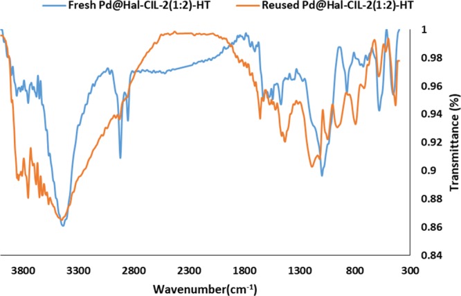
FTIR spectra of fresh and recycled Pd@Hal–CIL-2(1:2)-HT.
Finally, to investigate whether recycling of Pd@Hal–CIL-2(1:2)-HT could cause any aggregation of Pd nanoparticles, TEM images of recycled Pd@Hal–CIL-2(1:2)-HT were obtained (Figure 11). As illustrated, similar to fresh Pd@Hal–CIL-2(1:2)-HT, in the recycled catalyst Pd nanoparticles are distributed on the surface of the support homogeneously without aggregation.
Figure 11.

TEM image of recycled Pd@Hal–CIL-2(1:2)-HT.
Conclusions
Pd@Hal–CIL-2(1:2)-HT was prepared through a three-step procedure, in which CIL-2 was first prepared via carbonization of a novel IL synthesized from the reaction of TCT and 1-methyl imidazole, followed by hybridization with Hal under hydrothermal condition and Pd immobilization. The nanocomposite was then used as an efficient and heterogeneous catalyst for the hydrogenation of nitroarenes. It was revealed that the carbonization temperature can significantly affect the features of the resulting CIL. Moreover, the hybridization procedure could influence the catalytic activity of the resulting nanocomposite. In the sample prepared via carbonization of IL in the presence of Hal, the structure of Hal was destructed and the resulting nanocomposite showed inferior catalytic activity. The study of the ratio of Hal/CIL also disclosed that the optimum ratio was 1:2 and the lower content of CIL resulted in a less efficient catalyst. This was attributed to the role of CIL in more effective anchoring of Pd nanoparticles. Notably, the catalyst, Pd@Hal–CIL-2(1:2)-HT, was highly selective toward the nitro group and showed good recyclability.
Experimental Section
Materials and Instruments
All chemicals and solvents including 1-methyl imidazole, cyanuric chloride (TCT), zinc chloride, Hal, NaBH4, Pd(OAc)2, DMSO, MeOH, Et2O, deionized water, toluene, ethyl acetate, and n-hexane were received from Sigma-Aldrich. The hydrogenation reaction was performed by using nitroarenes as the substrate. All the chemicals were of analytical grade and used without further purification. The progress of the reactions was monitored by thin-layer chromatography (TLC) on commercial aluminum-backed plates of silica gel 60 F254, which was visualized using ultraviolet light. Notably, all the organic products were known, and their identification was performed by comparing their melting points for solid products in open capillaries using an Electrothermal 9100 and FTIR spectra with those of authentic samples.
The Philips CM30300Kv field emission transmission electron microscope was used for studying the morphology of the nanocomposite. Powder XRD patterns were recorded by using Siemens. TGAs were accomplished by using a METTLER TOLEDO instrument. To carry out the analysis, the samples were heated under inert atmosphere with a heating rate of 10 °C min–1 over the range of 40–800 °C. FTIR spectra of all carbons and nanocomposites were recorded by the PerkinElmer-Spectrum 65 instrument using KBr pellets. The nitrogen adsorption and desorption isotherms were obtained using a BELSORP Mini II. For this analysis, all the samples were preheated at 200 °C for 3 h. The Raman spectra of the prepared carbon materials were recorded by using the TEKSAN-N1-541 spectrum at k = 532 nm instrument. The 1H NMR and 13C NMR spectra were recorded by a Bruker DRX-500 spectrometer. The ultrasonic apparatus employed for the synthesis of nanocomposites was Bandelin HD 3200 that was equipped with tip TT13 with the output power between 100 and 200 W. Metal loading and leaching on the catalyst were measured by using the ICP analyzer (Varian, Vista-pro).
Catalyst Preparation
Synthesis of TCT-IMI Ionic Liquid
To synthesize TCT-IMI, cyanuric chloride (50 mmol) was dissolved in 50 mL of toluene, and the solution was heated up to 110 °C under reflux condition. Subsequently, a solution of 1-methyl imidazole (160 mmol) in 60 mL of toluene was added to the aforementioned solution in a stepwise manner. More precisely, a solution of 1-methyl imidazole (50 mmol in 20 mL of toluene) was first added, and the mixture was stirred for 24 h. Second, the second portion of 1-methyl imidazole (50 mmol in 20 mL of toluene) was introduced, and the resulting solution was mixed for 24 h. Finally, the third portion of 1-methyl imidazole (60 mmol in 20 mL of toluene) was added, and stirring was continued for 48 h under Ar atmosphere. Upon completion of the reaction, the mixture was cooled to room temperature, and the yellowish product was filtered over a Buchner funnel. To purify the product, the obtained material was successively washed with excess Et2O and toluene and dried in an oven at 100 °C for 12 h to furnish pure TCT-IMI.
Synthesis of CIL-1
To synthesize CIL 1, TCT-IMI (3 g) and ZnCl2 (12 g) were mixed and ground thoroughly. Then, the obtained paste was transferred into a quartz tube (10 × 50 cm) and heated under programmed temperature (heating at 300 °C for 0.5 h, followed by heating at 700 °C for 5 and 1 h at 900 °C) in a tubular furnace under N2 atmosphere. After cooling to room temperature, the obtained black powder was ground. To remove the catalyst, the resulting carbon was stirred in HCl (3 M, 250 mL) for 24 h. Finally, the resulting black powder was filtered off, washed successively with water and EtOH, and dried in an oven at 100 °C for 24 h.
Synthesis of CIL-2
CIL-2 was prepared using the similar procedure that was applied for CIL-1, except the heating program was different. The used heating program was initially heated at 400 °C for 4 h, followed by heating at 900 °C for 1 h.
Synthesis of Hal–CIL-2(1:2)-HT
Hal–CIL-2-HT was prepared by using the hydrothermal method. Initially, CIL-2 (2 g) and Hal (1 g) were mixed in deionized water (100 mL) and homogenized under ultrasonic irradiation of power 150 W for 0.5 h. Subsequently, the resulting suspension was transferred into an autoclave and heated at 220 °C for 48 h. At the end of the reaction, the reactor was cooled to room temperature, and the obtained black powder was filtered over a Buchner funnel, washed thoroughly with water, and then dried in an oven at 100 °C for 24 h. Notably, apart from the main sample, Hal–CIL-2(1:2)-HT, other samples, Hal–CIL-2(1:1)-HT and Hal–CIL-2(2:1)-HT with different ratios of Hal/CIL, were synthesized under the same condition used for the synthesis of Hal–CIL-2(1:2)-HT.
Synthesis of Hal–CIL-2(1:2)-C
TCT-IMI IL (3 g), ZnCl2 (12 g), and Hal (1 g) were mixed and ground to soft dough. Subsequently, the obtained yellowish dough was transferred into a quartz tube (10 × 50 cm) and carbonized under N2 atmosphere. The heating program was as follows: heating at 400 °C in a tubular furnace, followed by further treatment at 900 °C for 1 h. Upon completion of the carbonization, the reactor was cooled to room temperature, and the resulting black solid was suspended in HCl (3 M, 250 mL) and stirred for 24 h to remove ZnCl2. The product was further purified by washing with water and EtOH. Finally, the resulting solid (Hal–CIL-2(1:2)-C) was dried in an oven at 100 °C for 24 h.
Incorporation of Pd into Different Supports, That Is, Hal, CIL-1, CIL-2, Hal–CIL-2(1:2)-HT, and Hal–CIL-2(1:2)-C
Immobilization of Pd nanoparticles on the support was achieved through the wet-impregnation procedure. Briefly, 1.2 g of the support was added to 30 mL of toluene and sonicated for 0.5 h to furnish a well-dispersed suspension. Then, a solution of 0.1 mmol of Pd(OAc)2 in 20 mL of toluene was added to the above-mentioned suspension in a dropwise manner. After stirring at room temperature for 2 h, a solution of reducing agent, that is, NaBH4 in H2O (10 mL, 0.2 N), was introduced to furnish Pd(0) nanoparticles. Finally, the precipitate was filtered, washed three times with MeOH, and dried in an oven at 100 °C for 12 h. The general synthetic procedure of the catalyst is shown in Figure 1.
Catalyst Application: General Procedure for the Hydrogenation Reaction of Nitroarene
In a typical process for nitroarene hydrogenation, an appropriate amount of solid catalyst (1 wt %) was added into a mixture of nitroarene (1 mmol) in 3 mL of deionized water in a three-necked flask at room temperature. After purging with hydrogen three times, the final pressure was adjusted to 1 bar, and the glass reactor was stirred vigorously. The progress of the reaction was traced by TLC (ratio of n-hexane/ethyl acetate solvent, 10:1). After the end of the reaction, the solid catalyst was separated by centrifuging at 5000 rpm and washed several times with deionized water and absolute ethanol. The separated catalyst was dried in an oven and reused for the next reaction run. The hydrogenized product was extracted with ethyl acetate (3 × 10 mL) and dried over anhydrous Na2SO4 and evaporated under vacuum to obtain the product.
Acknowledgments
The authors appreciate the partial supports from Iran Polymer and Petrochemical Institute and Alzahra University. S.S. and M.M.H. appreciate Iran National Science Foundation (INSF) for the Individual given grant no. 97009384. M. Malmir’s contribution is also appreciated.
Glossary
Abbreviations
- Hal
halloysite
- IL
ionic liquid
- CIL
ionic liquid-derived carbon
- HT
hydrothermally treated
Supporting Information Available
The Supporting Information is available free of charge on the ACS Publications website at DOI: 10.1021/acsomega.9b02887.
TGA as well as 1H NMR and 13C NMR spectra of TCT-IMI (PDF)
Author Contributions
The manuscript was written through contributions of all authors. All authors have given approval to the final version of the manuscript.
The authors declare no competing financial interest.
Supplementary Material
References
- Inagaki M.; Toyoda M.; Soneda Y.; Morishita T. Nitrogen-doped carbon materials. Carbon 2018, 132, 104–140. 10.1016/j.carbon.2018.02.024. [DOI] [Google Scholar]
- Gao J.; Ma N.; Zhai J.; Li T.; Qin W.; Zhang T.; Yin Z. Polymerizable Ionic Liquid as Nitrogen-Doping Precursor for Co-N-C Catalyst with Enhanced Oxygen Reduction Activity. Ind. Eng. Chem. Res. 2015, 54, 7984–7989. 10.1021/acs.iecr.5b01703. [DOI] [Google Scholar]
- Paul R.; Du F.; Dai L.; Ding Y.; Wang Z. L.; Wei F.; Roy A. 3D Heteroatom-Doped Carbon Nanomaterials as Multifunctional Metal-Free Catalysts for Integrated Energy Devices. Adv. Mater. 2019, 31, 1805598–1805624. 10.1002/adma.201805598. [DOI] [PubMed] [Google Scholar]
- Wütscher A.; Eckhard T.; Hiltrop D.; Lotz K.; Schuhmann W.; Andronescu C.; Muhler M. Nitrogen-Doped Metal-Free Carbon Materials Derived from Cellulose as Electrocatalysts for the Oxygen Reduction Reaction. ChemElectroChem 2019, 6, 514–521. 10.1002/celc.201801217. [DOI] [Google Scholar]
- Luo J.; Wang K.; Hua X.; Wang W.; Li J.; Zhang S.; Chen S. Pyridinic-N Protected Synthesis of 3D Nitrogen-Doped Porous Carbon with Increased Mesoporous Defects for Oxygen Reduction. Small 2019, 15, 1805325–1805333. 10.1002/smll.201805325. [DOI] [PubMed] [Google Scholar]
- Liang B.; Li K.; Liu Y.; Kang X. Nitrogen and phosphorus dual-doped carbon derived from chitosan: An excellent cathode catalyst in microbial fuel cell. Chem. Eng. J. 2019, 358, 1002–1011. 10.1016/j.cej.2018.09.217. [DOI] [Google Scholar]
- Fu X.; Chen A.; Yu Y.; Hou S.; Liu L. Carbon Nanotube@N-Doped Mesoporous Carbon Composite Material for Supercapacitor Electrodes. Chem.—Asian J. 2019, 14, 634–639. 10.1002/asia.201801865. [DOI] [PubMed] [Google Scholar]
- Xie Z.-L.; Su D. S. Ionic Liquid Based Approaches to Carbon Materials Synthesis. Eur. J. Inorg. Chem. 2015, 2015, 1137–1147. 10.1002/ejic.201402607. [DOI] [Google Scholar]
- van Dommele S.; de Jonga K. P.; Bitter J. H. Nitrogen-containing carbon nanotubes as solid base catalysts. Chem. Commun. 2006, 4859–4861. 10.1039/b610208e. [DOI] [PubMed] [Google Scholar]
- Kudashov A. G.; Okotrub A. V.; Bulusheva L. G.; Asanov I. P.; Shubin Y. V.; Yudanov N. F.; Yudanova L. I.; Danilovich V. S.; Abrosimov O. G. Influence of Ni–Co Catalyst Composition on Nitrogen Content in Carbon Nanotubes. J. Phys. Chem. B 2004, 108, 9048–9053. 10.1021/jp048736w. [DOI] [Google Scholar]
- Salim N. V.; Blight S.; Creighton C.; Nunna S.; Atkiss S.; Razal J. M. The Role of Tension and Temperature for Efficient Carbonization of Polyacrylonitrile Fibers: Toward Low Cost Carbon Fibers. Ind. Eng. Chem. Res. 2018, 57, 4268–4276. 10.1021/acs.iecr.7b05336. [DOI] [Google Scholar]
- Vinu A.; Ariga K.; Mori T.; Nakanishi T.; Hishita S.; Golberg D.; Bando Y. Preparation and Characterization of Well-Ordered Hexagonal Mesoporous Carbon Nitride. Adv. Mater. 2005, 17, 1648–1652. 10.1002/adma.200401643. [DOI] [Google Scholar]
- Abo-Hamad A.; AlSaadi M. A.; Hayyan M.; Juneidi I.; Hashim M. A. Ionic Liquid-Carbon Nanomaterial Hybrids for Electrochemical Sensor Applications: a Review. Electrochim. Acta 2016, 193, 321–343. 10.1016/j.electacta.2016.02.044. [DOI] [Google Scholar]
- Zhang S.; Dokko K.; Watanabe M. Carbon materialization of ionic liquids: from solvents to materials. Mater. Horiz. 2015, 2, 168–197. 10.1039/c4mh00141a. [DOI] [Google Scholar]
- Paraknowitsch J. P.; Thomas A. Functional Carbon Materials From Ionic Liquid Precursors. Macromol. Chem. Phys. 2012, 213, 1132–1145. 10.1002/macp.201100573. [DOI] [Google Scholar]
- Fellinger T.-P.; Thomas A.; Yuan J.; Antonietti M. 25th Anniversary Article: ″Cooking Carbon with Salt″: Carbon Materials and Carbonaceous Frameworks from Ionic Liquids and Poly(ionic liquid)s. Adv. Mater. 2013, 25, 5838–5855. 10.1002/adma.201301975. [DOI] [PubMed] [Google Scholar]
- Rafiee M.; Karimi B.; Shirmohammadi H. Graphitized Nitrogen-Doped Ordered Mesoporous Carbon Derived from Ionic Liquid; Catalytic Performance Toward ORR. Electrocatalysis 2018, 9, 632–639. 10.1007/s12678-018-0472-4. [DOI] [Google Scholar]
- Miao L.; Zhu D.; Liu M.; Duan H.; Wang Z.; Lv Y.; Xiong W.; Zhu Q.; Li L.; Chai X.; Gan L. N, S Co-doped hierarchical porous carbon rods derived from protic salt: Facile synthesis for high energy density supercapacitors. Electrochim. Acta 2018, 274, 378–388. 10.1016/j.electacta.2018.04.100. [DOI] [Google Scholar]
- Zhao Y.; Kong W.; Jin Z.; Fu Y.; Wang W.; Zhang Y.; Liu J.; Zhang B. Storing solar energy within Ag-Paraffin@Halloysite microspheres as a novel self-heating catalyst. Appl. Energy 2018, 222, 180–188. 10.1016/j.apenergy.2018.04.013. [DOI] [Google Scholar]
- Massaro M.; Colletti C. G.; Buscemi G.; Cataldo S.; Guernelli S.; Lazzara G.; Liotta L. F.; Parisi F.; Pettignano A.; Riela S. Palladium nanoparticles immobilized on halloysite nanotubes covered by a multilayer network for catalytic applications. New J. Chem. 2018, 42, 13938–13947. 10.1039/c8nj02932f. [DOI] [Google Scholar]
- Massaro M.; Colletti C. G.; Lazzara G.; Milioto S.; Noto R.; Riela S. Halloysite nanotubes as support for metal-based catalysts. J. Mater. Chem. A 2017, 5, 13276–13293. 10.1039/c7ta02996a. [DOI] [Google Scholar]
- Liu Y.; Zhang J.; Guan H.; Zhao Y.; Yang J.-H.; Zhang B. Preparation of bimetallic Cu-Co nanocatalysts on poly (diallyldimethylammonium chloride) functionalized halloysite nanotubes for hydrolytic dehydrogenation of ammonia borane. Appl. Surf. Sci. 2018, 427, 106–113. 10.1016/j.apsusc.2017.08.171. [DOI] [Google Scholar]
- Li X.; Zhu W.; Yin Y.; Lu X.; Yao C.; Ni C. La1-xAgxFeO3/halloysites nanocomposite with enhanced visible light photocatalytic performance. J. Mater. Sci.: Mater. Electron. 2016, 27, 4180–4185. 10.1007/s10854-016-4280-4. [DOI] [Google Scholar]
- Xing W.-N.; Ni L.; Yan X.-S.; Liu X.-L.; Luo Y.-Y.; Lu Z.-Y.; Yan Y.-S.; Huo P.-W. Preparation of C@CdS/Halloysite Nanotube Composite Photocatalyst Using One-Step Pyrolytic Method and Its Photodegradation Properties. Acta Phys.-Chim. Sin. 2014, 30, 141–149. 10.3866/PKU.WHXB201311211. [DOI] [Google Scholar]
- Jiang L.; Huang Y.; Liu T. Enhanced visible-light photocatalytic performance of electrospun carbon-doped TiO2/halloysite nanotube hybrid nanofibers. J. Colloid Interface Sci. 2015, 439, 62–68. 10.1016/j.jcis.2014.10.026. [DOI] [PubMed] [Google Scholar]
- Lvov Y.; Wang W.; Zhang L.; Fakhrullin R. Halloysite Clay Nanotubes for Loading and Sustained Release of Functional Compounds. Adv. Mater. 2016, 28, 1227–1250. 10.1002/adma.201502341. [DOI] [PubMed] [Google Scholar]
- Vinokurov V.; Stavitskaya A.; Glotov A.; Ostudin A.; Sosna M.; Gushchin P.; Darrat Y.; Lvov Y. Halloysite nanotube-based cobalt mesocatalysts for hydrogen production from sodium borohydride. J. Solid State Chem. 2018, 268, 182–189. 10.1016/j.jssc.2018.08.042. [DOI] [Google Scholar]
- Lazzara G.; Cavallaro G.; Panchal A.; Fakhrullin R.; Stavitskaya A.; Vinokurov V.; Lvov Y. An assembly of organic-inorganic composites using halloysite clay nanotubes. Curr. Opin. Colloid Interface Sci. 2018, 35, 42–50. 10.1016/j.cocis.2018.01.002. [DOI] [Google Scholar]
- Yuan P.; Tan D.; Annabi-Bergaya F. Properties and applications of halloysite nanotubes: recent research advances and future prospects. Appl. Clay Sci. 2015, 112-113, 75–93. 10.1016/j.clay.2015.05.001. [DOI] [Google Scholar]
- Wei Y.; Yuan P.; Liu D.; Losic D.; Tan D.; Chen F.; Liu H.; Zhou J.; Du P.; Song Y. Activation of natural halloysite nanotubes by introducing lanthanum oxycarbonate nanoparticles via co-calcination for outstanding phosphate removal. Chem. Commun. 2019, 55, 2110–2113. 10.1039/c8cc10314c. [DOI] [PubMed] [Google Scholar]
- Dehghani S.; Sadjadi S.; Bahri-Laleh N.; Nekoomanesh-Haghighi M.; Poater A. Study of the effect of the ligand structure on the catalytic activity of Pd@ ligand decorated halloysite: Combination of experimental and computational studies. Appl. Organomet. Chem. 2019, 33, e4891 10.1002/aoc.4891. [DOI] [Google Scholar]
- Ma W.; Wu H.; Higaki Y.; Takahara A. Halloysite Nanotubes: Green Nanomaterial for Functional Organic-Inorganic Nanohybrids. Chem. Rec. 2018, 18, 986–999. 10.1002/tcr.201700093. [DOI] [PubMed] [Google Scholar]
- Vinokurov V.; Glotov A.; Chudakov Y.; Stavitskaya A.; Ivanov E.; Gushchin P.; Zolotukhina A.; Maximov A.; Karakhanov E.; Lvov Y. Core/Shell Ruthenium-Halloysite Nanocatalysts for Hydrogenation of Phenol. Ind. Eng. Chem. Res. 2017, 56, 14043–14052. 10.1021/acs.iecr.7b03282. [DOI] [Google Scholar]
- Bahri-Laleh N.; Sadjadi S.; Poater A. Pd immobilized on dendrimer decorated halloysite clay: Computational and experimental study on the effect of dendrimer generation, Pd valance and incorporation of terminal functionality on the catalytic activity. J. Colloid Interface Sci. 2018, 531, 421–432. 10.1016/j.jcis.2018.07.039. [DOI] [PubMed] [Google Scholar]
- Massaro M.; Schembri V.; Campisciano V.; Cavallaro G.; Lazzara G.; Milioto S.; Noto R.; Parisi F.; Riela S. Design of PNIPAAM covalently grafted on halloysite nanotubes as a support for metal-based catalysts. RSC Adv. 2016, 6, 55312–55318. 10.1039/c6ra06337c. [DOI] [Google Scholar]
- Bouchenafasaib N.; Grange P.; Verhasselt P.; Addoun F.; Dubois V. Effect of oxidant treatment of date pit active carbons used as Pd supports in catalytic hydrogenation of nitrobenzene. Appl. Catal., A 2005, 286, 167–174. 10.1016/j.apcata.2005.02.022. [DOI] [Google Scholar]
- Yu X.; Wang M.; Li H. Study on the nitrobenzene hydrogenation over a Pd-B/SiO2 amorphous catalyst. Appl. Catal., A 2000, 202, 17–22. 10.1016/s0926-860x(00)00454-3. [DOI] [Google Scholar]
- Giordano R.; Serp P.; Kalck P.; Kihn Y.; Schreiber J.; Marhic C.; Duvail J.-L. Preparation of rhodium catalysts supported on carbon nanotubes by a surface mediated organometallic reaction. Eur. J. Inorg. Chem. 2003, 610–617. 10.1002/ejic.200390083. [DOI] [Google Scholar]
- Li C.-H.; Yu Z.-X.; Yao K.-F.; Ji S.-F.; Liang J. Nitrobenzene hydrogenation with carbon nanotube-supported platinum catalyst under mild conditions. J. Mol. Catal. A: Chem. 2005, 226, 101–105. 10.1016/j.molcata.2004.09.046. [DOI] [Google Scholar]
- Arora N.; Mehta A.; Mishra A.; Basu S. 4-Nitrophenol reduction catalysed by Au-Ag bimetallic nanoparticles supported on LDH: Homogeneous vs. heterogeneous catalysis. Appl. Clay Sci. 2018, 151, 1–9. 10.1016/j.clay.2017.10.015. [DOI] [Google Scholar]
- Sadjadi S.; Akbari M.; Monflier E.; Heravi M. M.; Leger B. Pd nanoparticles immobilized on halloysite decorated with a cyclodextrin modified melamine-based polymer: a promising heterogeneous catalyst for hydrogenation of nitroarenes. New J. Chem. 2018, 42, 15733–15742. 10.1039/c8nj03014f. [DOI] [Google Scholar]
- Sadjadi S.; Heravi M. M.; Malmir M. Pd@HNTs-CDNS-g-C3N4: A novel heterogeneous catalyst for promoting ligand and copper-free Sonogashira and Heck coupling reactions, benefits from halloysite and cyclodextrin chemistry and g-C3N4 contribution to suppress Pd leaching. Carbohydr. Polym. 2018, 186, 25–34. 10.1016/j.carbpol.2018.01.023. [DOI] [PubMed] [Google Scholar]
- Sadjadi S.; Akbari M.; Léger B.; Monflier E.; Heravi M. M. Eggplant-Derived Biochar-Halloysite Nanocomposite as Supports of Pd Nanoparticles for the Catalytic Hydrogenation of Nitroarenes in the Presence of Cyclodextrin. ACS Sustainable Chem. Eng. 2019, 7, 6720–6731. 10.1021/acssuschemeng.8b05992. [DOI] [Google Scholar]
- Denisov V. N.; Mavrin B. N.; Serebryanaya N. R.; Dubitsky G. A.; Aksenenkov V. V.; Kirichenko A. N.; Kuzmin N. V.; Kulnitskiy B. A.; Perezhogin I. A.; Blank V. D. First-principles, UV Raman, X-ray diffraction and TEM study of the structure and lattice dynamics of the diamond–lonsdaleite system. Diamond Relat. Mater. 2011, 20, 951–953. 10.1016/j.diamond.2011.05.013. [DOI] [Google Scholar]
- Dennison J. R.; Holtz M.; Swain G. Raman Spectroscopy of Carbon Materials. Spectroscopy 1996, 11, 38–45. [Google Scholar]
- Filik J. Raman spectroscopy: a simple, non-destructive way to characterise diamond and diamond-like materials. Spectrosc. Eur. 2005, 17, 10–17. [Google Scholar]
- Higgins D. C.; Meza D.; Chen Z. Nitrogen-Doped Carbon Nanotubes as Platinum Catalyst Supports for Oxygen Reduction Reaction in Proton Exchange Membrane Fuel Cells. J. Phys. Chem. C 2010, 114, 21982–21988. 10.1021/jp106814j. [DOI] [Google Scholar]
- Cho Y. J.; Kim H. S.; Baik S. Y.; Myung Y.; Jung C. S.; Kim C. H.; Park J.; Kang H. S. Selective Nitrogen-Doping Structure of Nanosize Graphitic Layers. J. Phys. Chem. C 2011, 115, 3737–3744. 10.1021/jp112141f. [DOI] [Google Scholar]
- Zhang S.; Dokko K.; Watanabe M. Direct Synthesis of Nitrogen-Doped Carbon Materials from Protic Ionic Liquids and Protic Salts: Structural and Physicochemical Correlations between Precursor and Carbon. Chem. Mater. 2014, 26, 2915–2926. 10.1021/cm5006168. [DOI] [Google Scholar]
- Zhang S.; Dokko K.; Watanabe M. Carbon materialization of ionic liquids: from solvents to materials. Mater. Horiz. 2015, 2, 168–197. 10.1039/c4mh00141a. [DOI] [Google Scholar]
- Jin J.; Fu L.; Yang C.; Ouyang J. Carbon hybridized halloysite nanotubes for high-performance hydrogen storage capacities. Sci. Rep. 2015, 5, 12429. 10.1038/srep12429. [DOI] [PMC free article] [PubMed] [Google Scholar]
- Bordeepong S.; Bhongsuwan D.; Pungrassami T.; Bhongsuwan T. Characterization of halloysite from Thung Yai District, Nakhon Si Thammarat Province, in Southern Thailand. Songklanakarin J. Sci. Technol. 2011, 33, 599–607. [Google Scholar]
- Zatta L.; da Costa Gardolinski J. E. F.; Wypych F. Raw halloysite as reusable heterogeneous catalyst for esterification of lauric acid. Appl. Clay Sci. 2011, 51, 165–169. 10.1016/j.clay.2010.10.020. [DOI] [Google Scholar]
- Zhu H.; Du M.; Zou M.; Xu C.; Fu Y. Green synthesis of Au nanoparticles immobilized on halloysite nanotubes for surface-enhanced Raman scattering substrates. Dalton Trans. 2012, 41, 10465–10471. 10.1039/c2dt30998j. [DOI] [PubMed] [Google Scholar]
- Yuan P.; Southon P. D.; Liu Z.; Green M. E. R.; Hook J. M.; Antill S. J.; Kepert C. J. Functionalization of Halloysite Clay Nanotubes by Grafting with γ-Aminopropyltriethoxysilane. J. Phys. Chem. C 2008, 112, 15742–15751. 10.1021/jp805657t. [DOI] [Google Scholar]
- Zhang W.; Mu B.; Wang A. Halloysite nanotubes induced synthesis of carbon/manganese dioxide coaxial tubular nanocomposites as electrode materials for supercapacitors. J. Solid State Electrochem. 2015, 19, 1257–1263. 10.1007/s10008-014-2730-6. [DOI] [Google Scholar]
- Sadjadi S.; Bahri-Laleh N. CuI@amine-functionalized halloysite as an efficient heterogeneous catalyst for promoting A3 coupling reaction under ultrasonic irradiation: a combination of experimental and DFT simulation. J. Porous Mater. 2018, 25, 821–833. 10.1007/s10934-017-0495-x. [DOI] [Google Scholar]
- Feng G.; Chen P.; Lou H. Palladium catalysts supported on carbon–nitrogen composites for aqueous-phase hydrogenation of phenol. Catal. Sci. Technol. 2015, 5, 2300–2304. 10.1039/c4cy01647e. [DOI] [Google Scholar]
- Makowski P.; Cakan R. D.; Antonietti M.; Goettmann F.; Titirici M. M. Selective partial hydrogenation of hydroxy aromatic derivatives with palladium nanoparticles supported on hydrophilic carbon. Chem. Commun. 2008, 999–1001. 10.1039/b717928f. [DOI] [PubMed] [Google Scholar]
Associated Data
This section collects any data citations, data availability statements, or supplementary materials included in this article.