Abstract
We describe a method for using a generic head model, in the form of an anatomical atlas, to produce EEG source localizations. The atlas is fitted to the subject by a nonrigid warp using a set of surface landmarks. The warped atlas is used to compute a finite element model (FEM) of the forward mapping or lead‐fields between neural current generators and the EEG electrodes. These lead‐fields are used to localize current sources from the subject's EEG data and the sources are then mapped back to the anatomical atlas. This approach provides a mechanism for comparing source localizations across subjects in an atlas‐based coordinate system, which can be used in the large fraction of EEG studies in which MR images are not available. The Montreal brain atlas was used as the reference anatomical atlas and 10 individual MR volumes were used to evaluate the method. The atlas was fitted to each subject's head by a thin‐plate‐spline (TPS) warp. The spatial locations of a generic 155‐electrode configuration were used to constrain the warp. For the purposes of evaluation, dipolar sources were placed on the inner cortical surface in the atlas geometry and transferred to each subject's brain space using a polynomial warp. The parameters of the warp were computed using an intensity‐based matching of the atlas and subject brains, thus ensuring that the sources were placed at approximately the same anatomical location in each case. Data were simulated in the subject geometry and a dipole fit was performed on these data using an FEM of the TPS warped atlas. The source positions found in the warped atlas were transferred back to the original atlas and compared to the original position. Sources were simulated at 972 locations evenly distributed over the inner cortical surface of the atlas. The mean error over all 10 subjects was 8.1 mm in the subject space and 15.2 mm in the atlas space. In comparison, using an affine transformation of the electrodes into atlas space and an FEM model generated from the atlas produced mean errors of 22.3 mm in subject space and 19.6 mm in atlas space. With a standard three‐shell spherical model the errors were 27.2 mm in the subject space and 34.7 mm when mapped to atlas space. Hum Brain Mapp, 2005. © 2005 Wiley‐Liss, Inc.
Keywords: atlas, EEG, Montreal brain phantom, radial basis function, source localization, warping
INTRODUCTION
Multichannel electroencephalography (EEG), as compared to magnetoencephalography (MEG) or functional magnetic resonance imaging (fMRI), is a widely available and inexpensive method for measuring functional information about the human brain. The measured electric potentials can be used to determine the location and strength of neural current sources by means of an inverse procedure [Scherg, 1990; Mosher et al., 1992]. These sources can be modeled as equivalent current dipoles whose location and temporal activation characterize the brain's response to sensory, motor, or cognitive tasks. Ideally, individual anatomical MR scans of the subject are used, both for defining the forward model that relates source location and strength to the measured scalp potentials, and for visualizing and analyzing the estimated sources with respect to the cortical anatomy of the subject. In practice, EEG studies are often performed without accompanying anatomical scans. Here we describe a stereotactic atlas‐based procedure in which surface landmarks are used to warp an atlas to the subject's scalp morphology. The warped atlas is used to define a forward model for source localization. The source locations are then mapped back to the standardized atlas using an inverse warp. In this way, we can infer the approximate locations in cortical anatomy of EEG sources without access to an individual's MR image. Furthermore, the warping procedure allows the use of a standardized stereotactic coordinate system in the original atlas space for intersubject comparisons. Solution of the EEG inverse problem requires the solution of an associated quasistatic electromagnetic forward problem, which yields the scalp potential distribution for a given neural source [Hamalainen et al., 1993]. The simplest approach to this problem is to assume that the head consists of a set of nested spheres representing, for example, brain, CSF, skull, and scalp. This model can be solved analytically. Realistic head‐models, derived from the individual subjects head anatomy and electrical properties, increase the accuracy of the source localization as compared to the spherical head model [Buchner et al., 1996; Leahy et al., 1998]. A realistic model can be constructed from an anatomical image of the subject's head, coregistered with the sensor positions and segmented into regions of homogeneous conductivity [Wolters et al., 2002]. The geometry of the regions and the sensor positions are used with a boundary element method (BEM) or finite element method (FEM) to calculate the forward model. Dipole source locations can then be determined by combining this forward model with inverse procedures based on least squares [Scherg, 1990], signal subspace approaches [Mosher and Leahy, 1998], or beamforming techniques [van Veen et al., 1997]. The use of a standardized head‐model offers a compromise between individual MR‐based models and the oversimplifying sphere model. An earlier example of this approach is described by Fuchs et al. [ 2002], who applied an affine transformation to map the subjects coordinates to a generic head based on a limited set of cranial landmarks and showed reduced localization error relative to the spherical model. A problem with the use of a linear mapping is that the scalp electrode locations on the subject may not fall on the scalp of the linearly transformed generic head. Since the electrode locations can be readily measured using an inexpensive 3‐D spatial localization device, a nonlinear mapping can be used to ensure that the electrode locations do fall on the scalp of the warped generic head. Here we achieve this using a thin‐plate spline fitting procedure (TPS) [Bookstein, 1999] in which the electrode placement is constrained to follow a regular pattern based on the 10‐20 system [Jasper, 1958] or modifications to a larger number of electrodes. The 10‐20 system defines the locations of electrodes by regular placement along contours on the scalp uniquely determined from a limited set of cranial landmarks. Consequently, this procedure can be used to define the location of the correspondence points for the electrode locations on the generic head using these same landmarks. The fitting procedure produces a warping of the 3‐D coordinates of the generic head to match the morphology of the subjects scalp at the electrode locations. We then use a segmented version of the warped head or atlas to define and solve the forward problem using finite elements. The forward model based on this procedure allows us to localize equivalent current dipole models of neural activation. However, meaningful interpretation of these results requires that they be referenced to the subject's neuroanatomy. Since this is not available, instead we invert the TPS warp and view the sources with respect to the stereotactic coordinate system defined by the generic head atlas.
An alternative approach to constructing realistic head models in the absence of an MR image is presented by van't Ent et al. [ 2001]. In their method an expansion of the scalp, skull, and brain surfaces by spherical harmonics is computed for an anatomical database of 10 subjects and the coefficients of these expansions are used to characterize the surfaces between the different tissue types that are modeled using BEM. A model of the boundaries between the different tissue types for a new subject is constructed by modifying the coefficients of the scalp expansion from the database to match the head shape of the new subject. The skull and brain surfaces of the new subject are constructed by a linear transformation of the scalp expansion. As with our method, this approach generates a realistic volume conductor model in the absence of MR images. However, its main application is discussed with respect to MEG data, where typically reconstruction errors are less model‐sensitive than in EEG. In addition, no anatomical reference atlas is used and localization errors are assessed only in the individual subject coordinates, while our approach also focuses on the use of the atlas as a common stereotactic reference system.
Stereotactic systems have been in use for many years in the functional neuroimaging community, starting with the Talairach proportional grid system [Talairach and Tournaux, 1988]. More recently, atlases have been constructed from volumetric MR images of a single [Collins et al., 1998] or multiple [Mazziotta et al., 2001] subjects. Registration between subject and the atlas can be based on matching of landmarks, surfaces, or image intensity within the brain [Toga and Thompson, 2002]. The approach we describe here differs from these in the sense that the features that are used for registration of subject and atlas are external (cranial and electrode locations) rather than intracranial. We would expect better registration using brain landmarks, but under our assumption that there is no individual MRI available for the EEG subject, these landmarks are not available. However, the inherent uncertainty in EEG localizations, even when subject MR images are used to define the forward model [Awada et al., 1998], are such that highly accurate registration of the subject and atlas brain is not essential. Here we assess the viability of scalp‐based matching by quantifying the accuracy of source localization relative to both the individual and atlas coordinate systems. We present a quantitative analysis of the behavior of the generic head‐modeling approach using the Montreal Brain Phantom [Collins et al., 1998], which we match to the subject anatomy using the TPS as described above. For this evaluation we generated landmarks from individual geometries, which in turn were based on MR images of 10 volunteers. We used a 155‐electrode modification of the 10‐20 system with placement determined by the locations of the nasion and left and right preauricular points. To evaluate the approach, we computed errors in localization of sources at a large number of points distributed over the entire cortex for each subject. To allow comparison across subjects, the cortex in each individual was defined by first matching the atlas brain to each of the subject brains with a nonlinear intensity‐based warp using the AIR (automated image registration) software package [Woods et al., 1992]. We then mapped points on the atlas cortex to their corresponding locations in each of the 10 individual subjects to define the individual cortices.
For each of these points in each subject we computed the forward field using an FEM based on a segmentation of the individual subjects anatomy. The sources were then localized using a signal‐subspace‐based approach [Mosher and Leahy, 1998] with the forward model calculated using an FEM applied to the atlas head, warped to the subject using the TPS constrained by the electrode locations and external anatomical landmarks. These results were then used to compute statistics on the localization errors in the individual subject coordinates. By applying an inverse warp to each subject, we then mapped the locations back to the stereotactic atlas coordinate system and computed average localization errors and standard deviations in this coordinate system. For comparison, we also computed localization errors for inverse procedures based on a three‐shell spherical model. Furthermore, we compared our approach with that of Fuchs et al. [ 2002] in which the subjects' electrode locations are mapped to atlas space using an affine transformation. The forward model and localizations are then computed directly in atlas space and transferred by the inverse affine transformation back into individual subject coordinates.
MATERIALS AND METHODS
Source Localization Using a Generic Head Model
Overview
Our goal is to localize current dipole sources from EEG data in the real‐world coordinate system of the subject using a stereotactic coordinate system to define homologous locations in a standard brain atlas. The method consists of the following steps:
-
1
Measure the 3‐D spatial coordinates on the subject of standard external landmarks (nasion and left and right preauricular points) and of the scalp electrodes, which are arranged in a modification of the 10–20 configuration.
-
2
Using a TPS basis, warp the 3‐D atlas so that the landmarks and electrode locations on the atlas match up with those measured on the subject.
-
3
Solve the forward EEG problem using an FEM based on a segmented version of the atlas, after warping the atlas to the subject's coordinate system. This step has to be repeated for each new subject.
-
4
Use a dipole localization algorithm to fit the measured EEG data, using the warped atlas‐based FEM as the forward solution.
-
5
Plot locations of the estimated dipoles in the subject coordinates and also in the atlas coordinate system, with the latter coordinates determined using the inverse of the TPS warp.
This process is illustrated in Figure 1. We now describe each of these steps in more detail.
Figure 1.
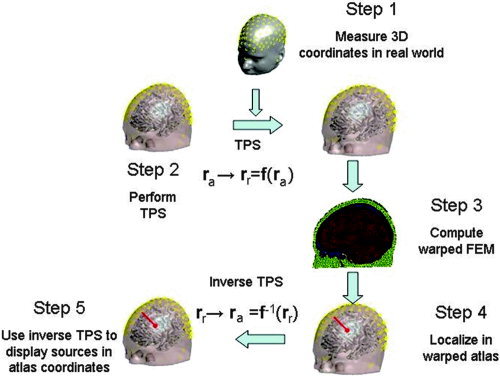
The generic head modeling approach: we compute an atlas‐to‐subject warp using the thin‐plate spline (TPS) in which the locations of the electrodes, in conjunction with nasion, inion, and preauricular points, serve as homologous landmarks. The coordinates of an FEM mesh, computed from the segmented atlas, are then transformed into the subject space using the TPS parameters. The warped FEM mesh is used to solve the forward EEG problem in subject coordinates and is also used as part of dipole localization procedure. Finally, the estimated dipole source locations are warped back into the atlas coordinate system using the inverse of the TPS transformation.
Electrode placement and feature points
We use a 155‐electrode configuration for both the subject and the brain atlas to compute the TPS warp. The electrode locations are generated from the measured locations of the nasion and left and right preauricular points (abbreviated as left and right points below) as follows: we first define a computer‐generated inion as the intersection of the scalp surface and the line passing through nasion and the midpoint between right and left points. The vertex is defined as the intersection with the scalp surface of the line perpendicular to the nasion‐right–left plane that passes through the midpoint between right and left points. Based on these five landmarks, on each geometry (i.e., atlas and the individual subjects) a generic electrode configuration is generated which is similar to the 10‐20 system. We note that, while this system is similar to the extended 10‐5 system of Oostenveld and Praamstra [ 2001], it is sufficiently different that we include a detailed description here. The system is defined by a number of curves on the scalp surface as illustrated in Figure 2. First, the sagittal curve formed by the intersection of the scalp surface and the nasion vertex/inion plane is defined. On this curve, electrodes are placed at 30%, 50%, and 70% of the length, i.e., at 20% intervals. Using points on this curve at 10% offsets to nasion and inion, we define a second plane parallel to the nasion‐left–right plane. The intersection of this plane with the scalp surface forms a circumferential curve on which electrodes are placed in 10% intervals, starting at 5% from its intersection with the sagittal curve. Combining opposing pairs on the circumferential curve and the positions on the sagittal curve, additional auxiliary planes can be defined. Corresponding auxiliary curves are generated by the intersection of the scalp with these planes and electrode positions are then generated at 33% intervals. In total, 19 electrode positions are generated by this scheme. An extension of the system to 155 electrodes is achieved by decreasing the intervals on the circumferential and sagittal curves as well as on the auxiliary curves. We reduced the interval on the sagittal curve to 10%, the intervals on the circumferential curve to 5%, and the intervals on the auxiliary curves to 10%. Since even intervals on the auxiliary curves lead to an overlap of the electrodes sitting at 50% with the electrodes on the sagittal curve, these positions were omitted. We also inserted another set of auxiliary curves between those generated by pairs of locations on the circumferential curve using virtual pairs of points at 5% intervals between the locations on the circumferential curve. Positions on these curves had an offset of 5% from the circumferential curves.
Figure 2.
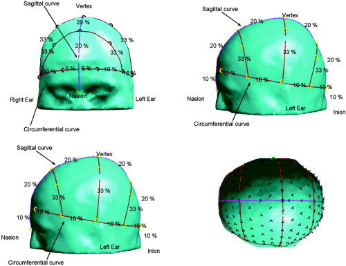
Generic 19 electrode configuration on the atlas. The circumferential line and the auxiliary lines are marked in red, the coronal line is marked in purple. The electrode positions are represented by black circles and the landmarks by green circles. The intervals in percentage of the line length are displayed between the electrode positions. The 155‐electrode configuration is shown in the lower right corner. The electrode positions are indicated by black crosses.
This particular choice of the electrode‐placing system is not required, but in order to perform the TPS warp for a given electrode configuration it is important that the measured electrode positions can be reproduced on the atlas. One alternative is to use the standard 10‐20 configuration based on the measured locations of the nasion, inion, and left and right preauricular points. By reproducing this arrangement on the atlas, we again have a set of homologous landmarks from which we can compute the TPS warp. For more dense electrode configurations we can use a subset of the electrodes, corresponding to the 10‐20 locations, to compute the TPS warp. This would be appropriate, for instance, in cases where the additional electrodes are not placed at regular intervals so that homologous locations cannot be defined on the atlas. In this case, the additional electrodes are not guaranteed to lie exactly on the scalp surface of the warped atlas, since only the landmarks are matched exactly. To solve this problem the additional electrodes are projected onto the atlas surface after applying the TPS warp. This method is implemented in the Brainstorm package (http://neuroimage.usc.edu/brainstorm) [Baillet et al., 2004]: a 10‐20 configuration is defined on the atlas with 19 electrodes positioned relative to the nasion, inion, and left and right preauricular points. This provides an exact mapping of the 10‐20 electrodes onto the warped atlas surface. Any additional electrodes are then projected onto the atlas surface.
Thin Plate Spline (TPS) Warp
The TPS has been widely used for nonrigid image registration based on feature‐point matching [Bookstein, 1996; Johnson and Christensen, 2002]. The method minimizes the bending energy necessary to deform an atlas coordinate system with respect to the subject image so as to match homologous points in the two images. The specific form of the bending energy is defined by analogy with a deformed thin metal plate. Among the attractive features of this method are that the coefficients of the basis functions that define the nonlinear warp can be computed as a linear function of the locations of the feature points and, unlike a polynomial basis, the deformations are local [Carr et al., 1997].
The TPS provides a mechanism for warping the atlas coordinates r a to those of the subject r r, so that the anatomical landmarks and electrode locations on the warped atlas match those on the subject's head. The transformation consists of an affine component plus a nonlinear warp using the thin‐plate basis functions w a (r a ). In 3‐D, the basis functions of the TPS have the form w a (r) = |r|. The transformation from atlas to subject space can be expressed as:
| (1) |
We denote the coordinates of the L landmarks in the atlas and subject space, respectively, as l and l , i= 1,… L. The matrix A a and vector t a represent the affine components of the transformation from atlas to subject. The affine coefficients A a, t a and TPS basis function coefficients w , i= 1,… L, are computed subject to the constraint Σi=1 L w a i = 0 by solving a square system of linear equations based on evaluating Eq. 1 at each landmark location. Substituting the resulting values back into Eq. 1 defines the warp. In order to map multiple subjects into a common atlas space for the purposes of evaluating the approach described here, we need to be able to map from the subject back into the atlas space. The TPS warp is one of an infinite set of possible transformations that will result in the registration of the two sets of landmarks. Applying the TPS procedure to define a mapping back from the subject to atlas does not result in the inverse of the TPS transformation from atlas to subject. However, the inverse r a(r r) = f ‐1(r r) can be found numerically by minimizing
| (2) |
with respect to the unknown atlas coordinates r a . Setting the derivative with respect to r a to 0 leads to a system of three nonlinear equations:
| (3) |
with
 the Jacobian of the TPS warp. This equation can be solved numerically using Newton's method to find the corresponding coordinates in atlas space. Good initial values for the solver are the coordinates obtained from the TPS warp from subject to atlas space.
Finite element method
After mapping the atlas to the subject coordinate system, we can use the anatomical structure of the atlas to compute a more accurate solution to the forward EEG problem than would result from using the standard spherical head model. We used FEM to find the numerical solution of the forward problem, i.e., to compute the scalp potentials resulting from an equivalent current dipole. Unlike the spherical head models, FEM is able to account for the effects of realistic head shape and of inhomogeneities in conductivity on scalp potentials. These properties are combined in a mesh‐based representation of the head and the potentials are then solved for on this mesh. The method used here is the sourceless dipole approach. The numerical solution is found as the sum of the analytical potential produced by a current dipole in an infinite homogeneous volume conductor and a finite residual potential computed from the FEM. The details and advantages of this method are described in van den Broek et al. [ 1996], Awada et al. [ 1997], and Marin et al. [ 1998]. For tetrahedral meshes of 10 mm side length, typical relative potential errors are less than 1% [Marin et al., 1998] when compared to the analytic solution for a three‐shell sphere model, which implies low localization errors as well. We used a 5 mm mesh, which should produce even lower errors. We compared our FEM with a three‐shell sphere analytical solution (radius for skin: 100 mm, outer skull: 92 mm, and inner skull: 87 mm, as used by Marin et al. [ 1998]), i.e., we simulated two sources with the FEM of the sphere and used the analytical model to localize these sources. We found a localization error for the deep source (i.e., 20 mm distance from the skull) of 0.4 mm and 0.9 mm for the source close to the skull (5 mm distance). While the mesh is deformed by each individual mapping to a subject, the mesh connectivity remains unchanged. This makes it necessary to recompute the FEM for each new subject, while it saves the steps of segmenting and tessellating the atlas.
Dipole source localization
The method described here can in principle be combined with any EEG inverse procedure. The generic head model is used to define the forward model and hence will affect only the forward computation. FEM calculations can be combined with all of the well‐known EEG inverse methods. Since we do not have access to a high‐resolution representation of the subject's cortical surface, we do not combine our approach with cortically constrained imaging methods [Dale and Sereno, 1993; Baillet and Garnero, 1997]. In the simulations described below we evaluate the impact of the generic head model on source localization accuracy for a single dipole only. Since only a single dipole was used in the simulations and no noise was added to the simulated forward potential, any other inverse method that is based on scanning with a dipole would have produced similar results to the RAP‐MUSIC scan results presented here. We evaluated the accuracy of the warp of the FEM model using simulations with a single dipole, for which we computed the forward potential and subsequently solved the inverse localization problem. Since we performed simulations for a large number of source locations, we had to use a procedure that required no user interaction. We therefore avoided a direct least‐squares fitting method, which is subject to trapping in local minima. Instead, we used the RAP‐MUSIC method, implemented in the Brainstorm toolbox, in which we scan through the entire head volume for dipolar sources and select dipole locations as those at which the dipolar source topography lies in a “signal subspace” estimated from the data [Mosher et al., 1992]. We used a rank three subspace and a 0.95 subspace correlation threshold; however, there were no cases where more than one source exceeded this threshold. The search grid was generated from the tessellation, using the centroid of each tetrahedral element as a grid point.
Comparisons across multiple subjects
The warped atlas can be used simply to define an improved head model. Localized dipoles can be viewed in the subject coordinates and approximately related to brain anatomy by overlaying these locations on the atlas‐brain, which is also brought into the subjects coordinate system through the TPS warping procedure. However, one of the attractions of using an atlas is that results from multiple subjects can be pooled by applying the inverse warp and mapping dipole locations from each subject back into the native coordinate system of the atlas using Eq. 2. As we describe below, we were able to use this procedure to evaluate the generic head‐modeling method in terms of localization errors with respect to the atlas coordinates, as well as in the individual subject coordinates.
Evaluation
Generation of data for individual subjects
To evaluate the impact of the generic head model on source localization accuracy, we performed simulation studies based on T 1‐weighted MRI volumes from 10 normal volunteers. For each subject we generated a set of cortical dipoles and simulated EEG potentials corresponding to each of these dipoles. We first describe the procedure for generating the cortical dipole locations in a manner that allows subsequent joint analysis of the localization errors. We then describe how the forward data were computed for each of these sources. To allow averaging of localization errors across the 10 subjects, we chose a set of 972 current dipole locations evenly distributed across the inner (white matter) cortical surface of the brain atlas shown in Figure 5. Dipole orientations were constrained to be normal to the atlas cortical surface. The surface was extracted from the labeled atlas using the tessellation tools in the BrainSuite software [Shattuck and Leahy, 2002] applied to the inner cortical surface defined in the labeled atlas. To define correspondence between these dipole locations in the atlas and subjects, we used an intensity‐based registration procedure to map the atlas brain onto the brains in each of the 10 subject MRIs. This registration procedure used the AIR software [Woods et al., 1992] to compute an intensity‐based fifth‐order polynomial warp to align the atlas and each of the subject brains. We then used the resulting warping parameters to map each of the atlas dipole locations to their corresponding coordinates in each of the 10 subject brains. The polynomial warp differs from our TPS approach since it uses the intensity distribution of the brain itself, rather than a restricted set of extracranial landmarks, for matching. Consequently, we can expect that the match between the coregistered atlas and each of the subjects will be significantly better than that obtained using the TPS. Intersubject registration errors of selected anatomical landmarks with AIR are on the order of 1.1 mm [Woods et al., 1998]. Note that we perform this polynomial warping only for the evaluation purpose of defining a homologous set of dipole locations for each subject. In this way we can compute mean and variance in the localization errors across subjects for each dipole. An example of the polynomial mapping from the atlas to subject for one source is shown in Figure 3. An example of the effect of the TPS warp is shown in Figure 4. While there is good correspondence between the scalp surface of the warped atlas and that of the subject, anatomical features within the brain are not so well aligned, since the TPS warp is based on scalp landmarks only.
Figure 5.
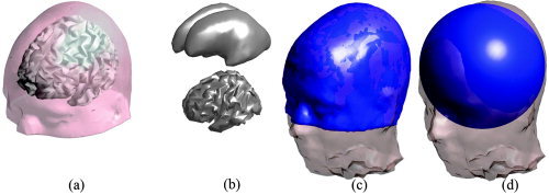
a: The Montreal atlas with the inner cortical surface as source space. b: The inner cortical surface (bottom) and a smoothed version of the same surface (top). c: The atlas geometry (blue), after applying the surface based warp, overlaid on the corresponding real geometry. d: The fitted sphere (blue) overlaid on the real geometry.
Figure 3.
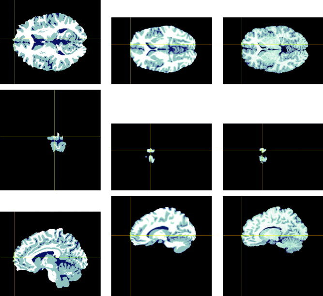
The first column shows three orthogonal views of the original atlas brain. The crosshair shows a source location. The second column shows the atlas brain with source after application of the polynomial warp. The third column shows the three corresponding orthogonal views of the subject MR. Note that the anatomical location of the source in the warped atlas corresponds approximately to that in the subject MR.
Figure 4.
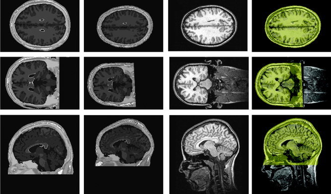
The first column shows the unwarped atlas brain. The MR image block has been padded to match the size of the real MR image (256 × 256 × 170 voxels). The second column shows the three views of the atlas brain after application of the TPS warp. The third column shows the corresponding slices of the original MR image. The fourth column shows the overlay of the warped Montreal atlas (yellow) onto the original geometry.
The MR image for each subject was used to compute simulated EEG data for each dipole location. Tissue labels for brain, cerebro‐spinal‐fluid (CSF), skull, and scalp were created for these images using the semiautomatic procedure implemented in the BrainSuite software tool [Shattuck and Leahy, 2002]. These labeled tissues were tessellated into tetrahedral elements of ∼5 mm side length. Standard conductivities for skin (0.21 S/m), skull (0.004 S/m), CSF (0.4 S/m), and brain (0.4 S/m) were assumed [Geddes and Baker, 1967]. We then applied the FEM procedure described above to each subject to compute the potentials for the set of 155 EEG electrodes for each of the 972 dipole locations for each of 10 subjects. These data were then used to evaluate localization accuracy using the generic head modeling approach.
Evaluation procedure
Evaluation consisted of applying the generic head‐modeling approach to each of the 10 subjects, localizing each of the 972 dipoles, and computing the resulting localization errors in subject and atlas space. For comparison, we also performed dipole localization of the same data using a three‐shell spherical head model. The evaluation procedure can be summarized in the following steps: the first three steps correspond to data acquisition in a real experiment, the remaining steps apply the generic and spherical head models for localization of equivalent current dipoles from this data with respect to the individual subject's brain using the parameters of the intensity‐based polynomial warp r a → r r:
-
1
Calculate the potentials for a single equivalent dipole at the selected source location, using an FEM based on a segmentation of the subject's MRI image, for each of the 155 EEG scalp electrode locations computed for that subject.
-
2
Compute a TPS warp of the brain atlas to the subject geometry using the surface landmarks.
-
3
Estimate the location, r , of the dipole in the subject's coordinates using MUSIC and an FEM forward model based on the brain atlas after TPS warping of the mesh to match the subject's surface landmarks.
-
4
Apply an inverse warp, to transfer the source location r into the atlas coordinates, r using the inverse TPS from subject to atlas.
-
5
Repeat Steps 3 and 4 using a spherical head model instead of the FEM.
This procedure was repeated for each of the 972 dipole locations and 10 subjects.
The localization error for each dipole was computed in subject coordinates as:
| (4) |
Because the simulated sources were originally positioned in atlas coordinates, the locations at r a and r are directly comparable, and the quantity
| (5) |
can be interpreted as the localization error in the atlas coordinate system. Since the atlas coordinates can be associated with anatomical features, the error e a can be viewed as the anatomical localization error of the procedure.
There are two sources of localization error in atlas space. The first is the model‐based error due to dipole localization errors in subject coordinates, resulting from the use of the atlas‐based head model rather than one based on the subjects own MR image. The second is a geometrical or transfer error due to a mismatch between the polynomial warp from atlas to subject, and the inverse TPS warp from subject to atlas. In a practical application we will not have subject MRs available and so cannot separate these two errors. However, it is informative to separately examine the contributions of each of these sources to the overall localization error. Let g(r a) represent the polynomial warp from the atlas to the individual subject, then the transfer error e t is given by:
| (6) |
In order to compare the realistic model with the sphere, we replaced the warped atlas in Step 6 by a standard three‐layer sphere, which was fitted to the individual electrodes, such that the distance between the surface and the electrodes was minimized. The ratios for the radii of the brain/CSF, skull, and skin compartment were 87%, 92%, and 100% of the total sphere‐radius. The conductivities were the same as for the realistic model. By transferring the sphere coordinates to atlas coordinates we can again compare localization errors across subjects in an anatomical coordinate system. The same error measure can then be applied for the sphere‐based reconstruction as for the atlas. Figure 5 shows an example of the fitted atlas and the sphere model. Both are overlaid onto the individual geometry.
Comparison with affine transformations
In order to compare the warped atlas with an unwarped precomputed standard model, e.g., as proposed by Fuchs et al. [ 2002], we used a similar method and performed an affine transformation of the individual electrode positions into the atlas coordinate system. While Fuchs et al. [ 2002] used a rigid transformation and scaling of the electrodes based on the right left and nasion landmarks, we used an affine transformation. The affine transformation was computed from the nasion, the left preauricular point, the right preauricular point, and the vertex, such that these landmarks match after the transformation into atlas space. The individual electrode positions were then transformed into atlas space and projected onto the skin surface of the atlas. Instead of interpolating a fixed precomputed forward model for the atlas, as described in Fuchs et al. [ 2002], we recomputed the model for each individual electrode configuration. We conducted a similar evaluation of this approach to that described above: we simulated sources in the individual geometry, but instead of warping the atlas, we used the atlas with the affine transformed individual electrodes for dipole localization. In order to match sources in atlas space no further transformation is required, as sources are already localized in this space. Sources in the individual subject space were compared by applying the inverse affine transformation to the reconstructed source positions.
RESULTS
Localization Accuracy in Subject Coordinates
In Figure 6 we compare the localization error in the subject coordinates for each dipole location for inverse solutions based on an FEM forward model using the TPS warped atlas and in Figure 7 for solutions based on the affine transformation of electrodes. For visualization purposes, we show these errors mapped onto a smoothed representation of the inner cortical surface of the atlas. The average errors for each subject, computed over the entire cortical surface, are shown in Figure 8 for the spherical model and the two atlas‐based models. The overall mean localization error in subject space was 8.1 mm (SD (standard deviation) = 4.4 mm) for the warped atlas‐based FEM forward model, 22.3 mm (SD = 4.6 mm) for the affine transform‐based atlas model, and 27.2 mm (SD = 5.0 mm) for the spherical model.
Figure 6.
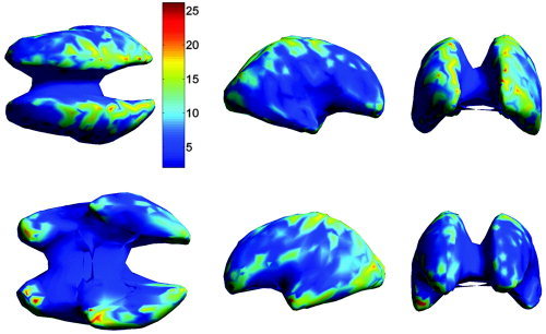
The mean localization error (in mm) in the individual subject space, averaged over all subjects, as a function of cortical location. Each dipole location was estimated using an FEM forward model based on the TPS warped atlas, with the warping parameters computed using extracranial landmarks. For display purposes, in this and subsequent images, the location errors are mapped onto a smoothed representation of the inner cortical surface of the atlas. The views shown in the upper row are from left to right: dorsal, right, and rostral. The lower row shows the ventral, left, and caudal view.
Figure 7.
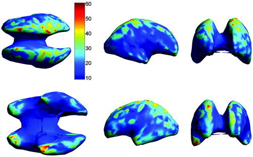
The mean localization error (in mm) in subject coordinates as in Figure 6, but with dipole locations computed using the affine transformed individual electrode positions in atlas space. The views shown in the upper row are from left to right: top, right, and front. The lower row shows the bottom, left, and back view.
Figure 8.
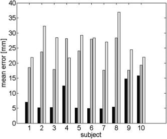
The mean localization error in the individual subject space for each of 10 individual subjects for the warped atlas‐based FEM (black), the affine transformation (gray), and spherical models (light gray). The averages were computed for each subject across the entire cortical surface.
Localization Accuracy in Atlas Coordinates
We next compare localization error in atlas space. In this case, we map each localized dipole into atlas coordinates using the inverse TPS transformation, and then compute localization errors across subjects for each dipole (Figs. 9, 10) and across the entire cortex for each subject (Fig. 11). The overall mean localization error in atlas space was 15.2 mm (SD = 5.9 mm) for the warped atlas‐based FEM forward model, 19.6 mm (SD = 3.6 mm) for the affine transform‐based atlas model, and 34.7 mm (SD = 6.6 mm) for the spherical model. The overall results averaged over subjects and cortical location are summarized in Table I.
Figure 9.
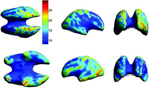
The mean localization error in the atlas space, averaged over all subjects, as a function of cortical location. Each dipole location was computed in subject coordinates using an FEM forward model computed from the TPS warped atlas. Dipole locations were then mapped back to atlas space using a second TPS transformation as described in Materials and Methods. The views shown in the upper row are from left to right: top, right, and front. The lower row shows the bottom, left, and back view.
Figure 10.
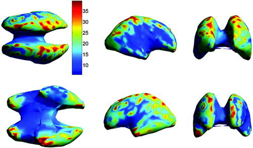
The mean localization error in atlas coordinates as in Figure 9, but with dipole locations computed using the affine transformation of electrodes into the atlas space. The views shown in the upper row are from left to right: top, right, and front. The lower row shows the bottom, left, and back view.
Figure 11.
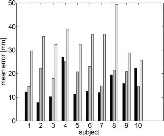
The mean localization error in atlas space for each of 10 individual subjects for the warped atlas based FEM (black), the affine transformation (gray), and spherical models (light gray). The averages were computed for each subject across the entire cortex after the sources were mapped back into atlas space using the TPS.
Table I.
Summary of localization errors across entire cortex for 10 subjects in both atlas and subject coordinates using either the TPS warped atlas to construct an FEM forward model (“Atlas”), the affine transformed electrode positions projected onto the atlas (“Affine”), or a spherical model (“Sphere”)
| Model | Coordinates | Average Error [mm] | SD [mm] |
|---|---|---|---|
| Atlas | Subject | 8.1 | 4.4 |
| Atlas | Atlas | 15.2 | 5.9 |
| Sphere | Subject | 27.2 | 5.0 |
| Sphere | Atlas | 34.7 | 6.6 |
| Affine | Subject | 22.3 | 4.6 |
| Affine | Atlas | 19.5 | 3.9 |
Impact of Transfer Errors on Localization Accuracy
As noted in the previous section, errors in the forward model and transfer errors in mapping between subject and atlas both contribute to the overall localization error. In Figure 12 we show the transfer error only, averaged across subjects, as a function of source location. Similarly, in Figure 13 we show the average transfer error for each subject, compared to the overall localization error, averaged over the entire cortex. The maximum transfer error over all subjects was 27.6 mm and the minimum 4.5 mm. The average transfer error over all subjects and all cortical locations was 11.5 mm with an SD of 6.4 mm.
Figure 12.
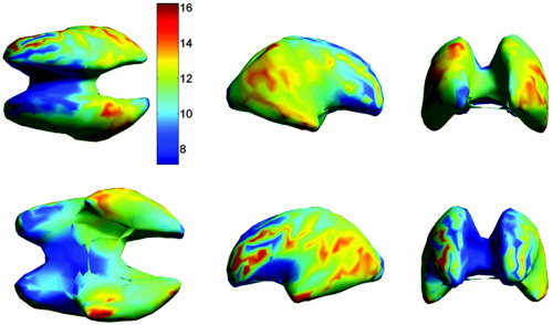
The transfer error in the atlas space, averaged over all subjects, as a function of cortical location. These errors show the combined effect of mapping from atlas to subject space using the intensity‐based polynomial warp followed by the inverse TPS transformation from subject to atlas as described in Materials and Methods. The views shown in the upper row are from left to right: top, right, and front. The lower row shows the bottom, left, and back view.
Figure 13.
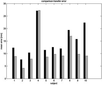
The transfer error (gray) in atlas space averaged across the entire cortex for each subject and compared to the overall localization error for the warped atlas based FEM (black).
DISCUSSION
The results presented above show reduced localization errors, both in native coordinates and in atlas space, when using FEM based on the TPS warped atlas rather than a spherical head model, or an affine transformation of individual electrodes into atlas space. These results are summarized in Figs. 8 and 11 for the two coordinate systems. In the native coordinate space the errors are only due to the model mismatch between the warped atlas (or sphere) and the individual model, and thus smaller than the errors in atlas space, which also incorporate the geometrical transfer error. The average error over all subjects and locations for the warped atlas is 8.1 mm, which is considerably lower than the 27.2 mm error for the sphere, or the 22.3 mm error for the affine transformation. The local error distribution on the cortical surface (see Fig. 6) shows that there are larger errors at locations that are close to the skull layer at the inferior frontal, and inferior and superior occipital lobes. Since the model itself is quite sensitive to inaccuracies in the skull representation [Huiskamp et al., 1999], the error becomes larger in these regions due to these model inaccuracies. While the FEM becomes less accurate for sources close to the skull, the FEM model error is small compared to the errors which are produced by warping the geometry (see Finite Element Method, above). The error distribution, however, is more homogeneous than that for the sphere, which exhibits particularly large errors (maximum error 127.9 mm) in the inferior and temporal regions of the brain, whereas the lowest errors can be found in the superior and central regions. This is in accordance with the fact that the upper parts of the head can be approximated quite well by a sphere, while this is not the case for the inferior and lower temporal and frontal regions. The spatial error distribution (see Fig. 7) for the affine transformation is similar to the error distribution for the warped atlas, with largest errors close to the skull, but increased in magnitude and also more homogeneous than the sphere. For atlas and sphere, the error is increased when one moves from individual coordinates back to the atlas coordinates, because the geometrical transfer error is added to the model mismatch error. This error is the same for both models and is strongest in the occipital and posterior temporal lobes (Fig. 12). These errors arise from a mismatch between the polynomial warp, which is based on the intensity variations in the atlas and subject brain, and the TPS warp, which is based on scalp landmarks only. These regions of larger error reflect those regions of cortex at which the TPS warp performs poorly in capturing intersubject variation in brain morphology compared to the intensity‐based polynomial warp. Because the model mismatch localization and transfer errors are summed as vectors, the transfer error does not necessarily have to increase the total error. Model mismatch and transfer errors could cancel each other, but on average (locally and over all subjects) this is not the case, as the overall increased errors show. The fractional contribution to the total error in atlas space by the transfer error is higher for the warped atlas than for the sphere, which is shown by the high positive directional correlation of the error in atlas space for the warped atlas model (0.6 in the sagittal direction, 0.6 in the axial direction, and 0.7 in the coronal direction, averaged over all subjects) and explains the 87% increase in error, from 8.1 mm to 15.2 mm, in moving from subject to atlas coordinates. For the sphere these correlations (0.4 in the sagittal direction, 0.4 in the horizontal direction, and 0.5 in the coronal direction) are lower, indicating that the errors for the sphere in atlas space are less affected by the transfer error. The localization error for the sphere in individual coordinates is large compared to the transfer error, and therefore the relative increase in error for the sphere (27.2 mm to 34.7 mm, 27% increase) is smaller compared to the warped atlas‐based head model. For the affine transformation, the errors are decreased (from 22.3 mm to 19.5 mm) rather than increased when considered in atlas space. This is due to the fact that the atlas space is already the natural space for reconstruction and no transfer error is involved. The increase when moving from atlas to subject space results from the mismatch between the inverse affine transformation and the polynomial warp and the fact that the affine transformation is not distance‐preserving. In all subjects the errors were considerably higher than the value reported by Fuchs et al. [ 2002]: the minimum average error was 14.5 mm as compared to 6.9 mm found by Fuchs et al. [ 2002]. One possible explanation for this discrepancy may be that our affine transformation allows shearing in addition to the translation and rotation described by Fuchs et al. [ 2002]. A second difference between the simulations performed in this work and the one by Fuchs et al. [ 2002] is that we simulated sources only on the cortical surface, while Fuchs et al. [ 2002] placed sources over the whole volume. Sources that are more superficial usually are easier to localize as compared to deep sources. However, in the situation of a single dipole and little or no noise, deep sources can be fit quite well and potentials of these sources are less affected by model discrepancies, thus producing smaller errors.
Of the 10 individual subjects, three exhibited particularly large errors in the subject space (Subjects 4, 9, and 10). We would expect larger errors to occur if subjects deviate significantly from the atlas in morphology. The transfer error can be used as a measure of morphological discrepancy, as it measures the difference between the polynomial warp (which is based on intensity of the internal features of the anatomy, i.e., the brain) and the surface‐based TPS warp (which is based on external landmarks). The stronger the morphological discrepancy between individual and atlas, the larger the deformation by the polynomial warp will be and the larger the transfer error. This error is largest in Subject 4, indicating that the shape of the inner cortical surface for this subject cannot be approximated well by the deformed atlas cortical surface using the TPS warp. Subjects 9 and 10 do not exhibit unusually large transfer errors, but they both have distinctive features: Subject 9 has a more curved upper skull than the other subjects and Subject 10 had the largest head (by volume) among all subjects. The combined average skin/skull thickness was also the largest among all subjects. There might be other morphological features (i.e., average skull thickness, average skin thickness, the spatial distribution of these, unusual head shapes, etc.) that can have an influence on the localization error, but in order to identify these, anatomical data would be required. Based on the measurement of surface landmarks alone, it is unlikely that we can identify subjects in which these large discrepancies might occur.
CONCLUSION
Based on the analysis of 10 individual subjects with a wide variety of headshapes, we have demonstrated that EEG‐based dipole localization using a forward model based on a TPS warped atlas performs substantially better than the widely used three‐shell sphere model and also outperforms a generic model that uses an affine transformation of the individual electrode positions. When computed in individual head coordinates, the average error for the TPS warped atlas was almost 20 mm lower than that for the sphere and 14 mm lower than that for the affine transformation of the electrodes into atlas space. Analyzing these errors locally on the inner cortical surface showed significant spatial variation for all models; however, the errors had different origins. Skull thickness mismatch and transfer error were the major sources of error for the atlas, while for the sphere and the affine transformed electrode model, the major source of error appears to be general mismatch in shape. If the atlas is also used to define a stereotactic coordinate system in which to pool data from multiple subjects, then localization errors in the atlas space will increase compared to those in the native subject coordinates, due to the transfer error caused by morphological differences between the atlas and individual subjects. In this case, the atlas‐based forward model leads to considerably smaller errors than a spherical model (average error 34.7 mm, SD 6.6 mm) and to slightly smaller errors that the affine model (average error 19.5. mm, SD 3.9 mm).
REFERENCES
- Awada K, Jackson D, Williams J, Wilton D, Baumann S, Papanicolaiu A (1997): Computational aspects of finite element modeling in EEG source localization. IEEE Trans Biomed Eng 44: 736–752. [DOI] [PubMed] [Google Scholar]
- Awada K, Jackson D, Baumann S, Williams J, Fink P, Prasky B (1998): Effect of conductivity uncertainties and modeling errors on EEG source localization using a 2‐D model. IEEE Trans Biomed Eng 45: 1135–1145. [DOI] [PubMed] [Google Scholar]
- Baillet S, Garnero L (1997): A Bayesian approach to introducing anatomo‐functional priors in the EEG/MEG inverse problem. IEEE Trans Biomed Eng 44: 374–385. [DOI] [PubMed] [Google Scholar]
- Baillet S, Mosher JC, Leahy RM (2004): Electromagnetic imaging using BrainStorm In: IEEE International Symposium on Biomedical Imaging: Macro to Nano, 2004. New York: IEEE; p 652–655. [Google Scholar]
- Bookstein F (1996): Landmark methods for forms without landmarks: morphometrics of group differences in outline shape. Med Image Anal 1: 225–243. [DOI] [PubMed] [Google Scholar]
- Bookstein F (1999): Linear methods for nonlinear maps: procrustes fits, thin‐plate splines, and the biometric analysis of shape variability In: Toga A, editor. Brain warping. New York: Academic Press; p 157–181. [Google Scholar]
- Buchner H, Waberski T, Fuchs M, Wischmann H, Wagner M, Drenckhahn R (1996): Comparison of realistically shaped boundary element and spherical head models in source localization of early somatosensory evoked potentials. Brain Topogr 8: 137–143. [DOI] [PubMed] [Google Scholar]
- Carr J, Fright W, Beatson R (1997): Surface interpolation with radial basis functions for medical imaging. IEEE Trans Med Imag 16: 96–107. [DOI] [PubMed] [Google Scholar]
- Collins D, Zijdenbos A, Kollokian V, Sled J, Kabani N, Holmes C, Evans A (1998): Design and construction of a realistic digital brain phantom. IEEE Trans Med Imag 17: 463–468. [DOI] [PubMed] [Google Scholar]
- Dale A, Sereno M (1993): Improved localization of cortical activity by combining EEG and MEG with MRI cortical surface reconstruction: a linear approach. J Cogn Neurosci 5: 162–176. [DOI] [PubMed] [Google Scholar]
- Fuchs M, Kastner J, Wagner M, Hawes S, Ebersole J (2002): A standardized boundary element method volume conductor model. Clin Neurophysiol 113: 702–712. [DOI] [PubMed] [Google Scholar]
- Geddes L, Baker L (1967): The specific resistance of biological materials — a compendium of data for the biomedical engineer and physiologist. Med Biol Eng 5: 271–293. [DOI] [PubMed] [Google Scholar]
- Hamalainen M, Hari R, Ilmoniemi RJ, Knuutila J, Lounasmaa OV (1993): Magnetoencephalography—theory, instrumentation, and applications to noninvasive studies of the working human brain. Rev Mod Phys 65: 413–498. [Google Scholar]
- Huiskamp G, Vreijenstijn M, Dijk R, Wieneke G, van Huffelen A (1999): The need for correct realistic geometry in the inverse EEG problem. IEEE Trans Biomed Eng 46: 1281–1287. [DOI] [PubMed] [Google Scholar]
- Jasper H (1958): The ten twenty electrode system of the international federation. J Clin Neurophysiol 10: 371–375. [PubMed] [Google Scholar]
- Johnson H, Christensen G (2002): Consistent landmark and intensity based image registration. IEEE Trans Med Imag 21: 450–461. [DOI] [PubMed] [Google Scholar]
- Leahy R, Mosher J, Spencer M, Huang M, Lewine J (1998): A study of dipole localization accuracy for MEG and EEG using a human skull phantom. Clin Neurophysiol 107: 159–173. [DOI] [PubMed] [Google Scholar]
- Marin G, Guerin C, Baillet S, Garnero L, Meunier G (1998): Influence of skull anisotropy for the forward and inverse problem in EEG: simulation studies using FEM on realistic head models. Hum Brain Mapp 6: 250–269. [DOI] [PMC free article] [PubMed] [Google Scholar]
- Mazziotta J, Toga A, Evans A, Fox P, Lancaster J, Zilles K, Woods R, Paus T, Simpson G, Pike B, Holmes C, Collins L, Thompson P, MacDonald D, Iacoboni M, Schormann T, Amunts K, Palomero‐Gallagher N, Geyer S, Parsons L, Narr K, Kabani N, LeGoualher G, Boomsma D, Cannon T, Kawashima R, Mazoyer B (2001): A probabilistic atlas and reference system for the human brain: International Consortium for Brain Mapping (ICBM). Philos Trans R Soc Lond B 356: 1293–1322. [DOI] [PMC free article] [PubMed] [Google Scholar]
- Mosher J, Leahy R, Lewis P (1992): Multiple dipole modeling and localization from spatiotemporal MEG data. IEEE Trans Biomed Eng 39: 541–557. [DOI] [PubMed] [Google Scholar]
- Mosher JC, Leahy RM (1998): Recursive MUSIC: a framework for EEG and MEG source localization. IEEE Trans Biomed Eng 45: 1342–1355. [DOI] [PubMed] [Google Scholar]
- Oostenveld R, Praamstra P (2001): The five percent electrode system for highresolution EEG and ERP measurements. Clin Neurophysiol 112: 713–719. [DOI] [PubMed] [Google Scholar]
- Scherg M (1990): Fundamentals of dipole source potential analysis. Adv Audiol 6: 40–69. [Google Scholar]
- Shattuck D, Leahy R (2002): Brainsuite: an automated cortical surface identification tool. Med Image Anal 6: 129–142. [DOI] [PubMed] [Google Scholar]
- Talairach J, Tournaux P (1988): Co‐planar stereotaxic atlas of the human brain. New York: Thieme. [Google Scholar]
- Toga A, Thompson P (2002): New approaches in brain morphometry. Am J Geriatr Psychiatry 10: 13–23. [PubMed] [Google Scholar]
- van den Broek S, Zhou H, Peters M (1996): Computation of neuromagnetic fields using finite‐element method and Biot‐Savart law. Med Biol Eng 34: 21–26. [DOI] [PubMed] [Google Scholar]
- van Veen B, van Drongelen W, Yuchtman M, Suzuki A (1997): Localization of brain electrical activity via linearly constrained minimum variance spatial filtering. IEEE Trans Biomed Eng 44: 867–880. [DOI] [PubMed] [Google Scholar]
- van't Ent D, de Munck J, Kaas A (2001): A fast method to derive realistic BEM models for E/MEG source reconstruction. IEEE Trans Biomed Eng 48: 1434– 1443. [DOI] [PubMed] [Google Scholar]
- Wolters C, Kuhn M, Anwander A, Reitzinge S (2002): A parallel algebraic multigrid solver for finite element method based source localization in the human brain. Comput Visual Sci 5: 165–177. [Google Scholar]
- Woods R, Cherry S, Mazziotta J (1992): Rapid automated algorithm for aligning and reslicing PET images. J Comput Assist Tomogr 16: 620–633. [DOI] [PubMed] [Google Scholar]
- Woods R, Grafton S, Watson J, Sicotte N, Mazziotta J (1998): Automated image registration. II. Intersubject validation of linear and nonlinear models. J Comput Assist Tomogr 22: 153–165. [DOI] [PubMed] [Google Scholar]


