

Abstract
Object related areas in the human ventral stream were previously shown to be activated, in a shape‐selective manner, by luminance, motion, and texture cues. We report on the preferential activation of these areas by stereo cues defining shape. To assess the relationship of this activation to object recognition, we employed a perceptual stereo effect, which profoundly affects object recognition. The stimuli consisted of stereo‐defined line drawings of objects that either protruded in front of a flat background (“front”), or were sunk into the background (“back”). Despite the similarity in the local feature structure of the two conditions, object recognition was superior in the “front” compared to the “back” configuration. We measured both recognition rates and fMRI signal from the human visual cortex while subjects viewed these stimuli. The results reveal shape selective activation from images of objects defined purely by stereoscopic cues in the human ventral stream. Furthermore, they show a significant correlation between recognition and fMRI signal in the object‐related occipito‐temporal cortex (lateral occipital complex). Hum. Brain Mapping 15:67–79, 2001. © 2001 Wiley‐Liss, Inc.
Keywords: object recognition, stereopsis, visual cortex, visual areas, fMRI, random dot stereograms, ventral stream, lateral occipital, neuroimaging
INTRODUCTION
Ventral stream visual areas have been known to participate in the object recognition process in both macaque and human visual systems [e.g., Logothetis and Sheinberg, 1996; Malach et al., 1995; Tanaka, 1997]. It has been shown that different types of visual cues (luminance, motion, texture) can activate these areas preferentially, provided they are used to define objects rather than non‐object textures or gratings [Grill‐Spector et al., 1998a; Kourtzi and Kanwisher, 2000a; Sary et al., 1993]. In particular, it has been shown that similar activation patterns were observed in an occipito‐temporal object‐related region (the lateral occipital complex, LOC) when objects were defined by coherent motion of dots, by texture boundaries, and by luminance boundaries [Grill‐Spector et al., 1998a]. An interesting question is whether stereo cues, which have been traditionally considered as related to dorsal stream processing [DeAngelis and Newsome, 1999; Livingstone and Hubel, 1988; Maunsell and Van Essen, 1983], could also activate ventral stream areas, when they are used in defining object form.
Another issue that has received substantial interest is to what extent activation in high‐order ventral‐stream areas is correlated with recognition performance. We have shown recently that the LOC manifests a high correlation to recognition in a rapid masking paradigm [Grill‐Spector et al., 2000]. Stereoscopic images [Julesz, 1971] provide a convenient means to study such correlation because it has been demonstrated that recognition level in such stimuli can be substantially manipulated [Fox and Patterson, 1981; Lehmkuhle and Fox, 1980]. By switching the local depth sign of stereoscopically defined contours, which entails only a minor change in the local feature structure, the overall recognizability of images of objects changes significantly.
In the present experiment, we used stereoscopic stimuli to both map the human cortical regions that are activated preferentially by stereoscopically‐defined object shapes, and to find what areas show correlation to the perceptual state of the observer. Our study demonstrates robust object‐selective, stereoscopic signals in human ventral stream cortical regions. Furthermore, our results show that fMRI signal in the object‐related lateral occipital complex (LOC), and particularly its anterior‐ventral part, the posterior fusiform gyrus (pFs), is correlated with recognition performance. Some of these results have been published in an abstract form [Gilaie Dotan et al., 2000].
MATERIALS AND METHODS
Subjects
Nine healthy subjects (7 male, 2 female, ages 22–33) with normal eyesight and with good stereopsis gave written informed consent to participate in the experiment after the nature of the experimental procedures was explained. Subjects' stereopsis was verified using a set of 14 stereo images of objects before the experiment. This image set was not used in the experiment. The Chaim Sheba Medical Center ethics committee approved the experimental protocol.
Functional MRI
Subjects were scanned on a 1.9 Tesla whole‐body scanner (2T Prestige, Elscint) with standard birdcage headcoil. Sagittal localizer, high resolution (0.8 × 1.5 × 4 mm) T1‐weighted images, and functional imaging EPI pulse sequences (T2*‐weighted, multi‐slice, gradient‐echo sequence; TR = 2,000 msec, TE = 45 msec, flip angle, 90°) with field of view 38.4 × 19.2 cm2, matrix size 128 × 72, and in‐plane resolution of 3 × 2.7 mm were acquired. Slices were oriented perpendicular to the calcarine sulcus. The scanned area included 12 slices 4 mm thick, and covered most of the occipital lobe, extending into parietal and temporal lobes. Head motions were minimized using stabilizing head foams.
Visual Stimuli
Visual stimuli were generated on a Windows 2000 PC and back‐projected via an Epson 5300 LCD projector onto a translucent screen located at the back of the scanner. Images were viewed through a tilted mirror, providing a maximal visual angle of 40° × 30°. The distance between the images and the subjects' eyes was 50 cm. Image size was 350 × 350 pixels, subtending visual angle of ∼15.74° × 15.74°.
Disparity‐defined (stereo) images were created using Julesz‐type random dot stereograms (RDS [Julesz, 1971]) and were viewed through red‐green glasses. Each of the RDS dots consisted of 2 × 2 pixels (0.089° visual angle). Two depth planes were created, each defined by a different shift between the red and green RDS channels (the green channel was shifted two RDS dots to the left of the red channel for first depth plane, and one RDS dot to the right for the second, so that the relative disparity between the two depth planes was three RDS dots (0.269° visual angle)). These two depth planes were used to generate all the disparity‐defined (stereo) stimuli in the experiment. The disparity‐defined figure‐shape/grating (“foreground”) was defined by one of the depth planes and the rest of the image (“background”) was defined by the other depth plane.
The stimulus set included 30 images of objects and six grating images (3 horizontal, 3 vertical), each defined by three different ways: one by luminance (black on white), and two by a difference in disparity (both a “front‐definition” when the first depth plane was used to define the shapes/gratings, whereas the second depth plane served as a “background”, and a “back‐definition” reversing the roles of the two depth planes). The stimulus set also included six different flat RDS images having no disparity difference between the two eyes, and a blank image. Altogether 90 images of objects, 18 gratings images, six flat RDS images and one blank image were used.
More specifically, the stimulus set can be categorized into seven categories according to the epoch types as follows (Fig. 1): 1) Luminance‐objects (LMO); common objects (such as bicycle, face, dog, chair) defined by black on white line drawings; 2) “Front”‐objects (FRO); the same line‐drawn objects but defined by RDS, using uncrossed disparity, so they appeared to “float” in front of the background surface; 3) “Back”‐objects (BKO); the same line drawings, defined by RDS but this time with crossed disparity so they appeared to be “sunk” behind the background surface; 4) Luminance‐gratings (LMG); luminance‐defined horizontal and vertical rectangular gratings; 5) “Front”‐gratings (FRG); same gratings but defined by RDS and appearing to float in front of the background surface; 6) “Back”‐gratings (BKG); same RDS‐defined gratings appearing to be sunk behind the background surface; and 7) Flat surface (fRDS); identical RDS (zero disparity) in both eyes that appeared as a flat surface.
Figure 1.
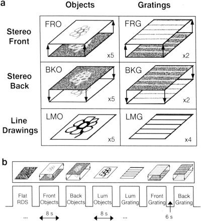
Stereo‐experiment: stimuli and time course. (a) Examples of the types of stimuli used in the experiment: Objects defined by random dot stereograms (RDS) that appeared either to float in front of the background surface, “front” objects (FRO), or to be sunk behind the surface, “back” objects (BKO). Black and white, luminance‐defined object line drawings (luminance objects (LMO)). Gratings defined by RDS that appeared either to float in front of the background surface, “front” gratings (FRG), or to be sunk behind the surface, “back” gratings (BKG). Black and white, luminance‐defined gratings (LMG). In addition, zero‐disparity RDS were also used as controls (fRDS). Number of epoch repetitions for each stimulus type on its lower right. (b) A sample of the epochs in the course of the experiment. Short block design. Epochs of 8 sec with 6 sec of interleaving blanks.
The line drawings were generated from the original objects by either tracing the contour of three‐dimensional objects (from the library of Viewpoint Data Labs) and adding a few inside details, or by scanning line drawn objects into the computer and refining them in Adobe Photoshop 5.0. After that the lines were automatically thickened using Adobe Photoshop “minimum” filter.
The contrast of the luminance images (black on white) was 100%. The blank image was a gray surface and its luminance level was equal to the mean luminance averaged over all images in the experiment. Luminance gratings were defined by 0.342 cycles per visual degree, black to white ratio: 15% black, 85% white) so that the total number of black pixels was equal to the mean number of black pixels of all the luminance‐object (LMO, see fMRI experiment) images. All images (including blank) had a fixation cross in the middle (bar length of 0.81° visual angle, width of 0.089°).
FMRI Experiment
The experiment consisted of seven conditions corresponding to the seven types of images as detailed in Visual Stimuli section and can be seen in Figure 1.
Each epoch lasted 8 sec and consisted of six images of the same condition presented at a rate of 0.75 Hz. This was done to allow sufficient time for fusion in the RDS epochs. Epochs were interleaved by a 6 sec blank period. The object‐condition epochs (LMO, FRO, BKO) were repeated five times each. The LMG and fRDS epochs were repeated four times each, and the FRG and BKG epochs were repeated two times each. Altogether the experiment consisted of 27 epochs. The number of epochs was chosen so as to optimize the testing of the activation to objects. The experiment started and ended with a 20 sec blank. The experiment lasted 412 sec. The images of corresponding LMO, FRO and BKO epochs were ordered randomly within epochs. To reduce priming effects, FRO and BKO images always appeared before their matching LMO image. Two of the five BKO epochs appeared before their corresponding FRO epoch.
Subjects wore the red‐green plastic glasses throughout the whole experiment. Subjects were instructed to fixate on a small fixation cross, and to covertly name images (for grating to indicate their direction: horizontal or vertical). To reduce the imbalance in naming difficulty of objects and gratings, grating orientation varied (horizontal and vertical) and the phase shifted.
Mapping borders of visual areas
For six of the subjects, we mapped in the same scanning session, after the main experiment, the representation of visual meridians to define borders of retinotopic areas. These subjects were used for the analysis of retinotopic areas (V1/V2 and V4/V8). Detailed description of the meridian mapping experiment is given in Grill‐Spector et al. [1998a,b]. Briefly, triangular wedges, compensating for the expanded foveal representation, consisting of gray scale natural images (half) or black and white texture objects (half) served as the visual stimuli. The wedges were presented in 16 sec blocks in four directions: left, right, up or down. Four cycles of each direction were shown with alternating blanks. Subjects were instructed to fixate on a central fixation cross.
Behavioral measurements
Behavioral data were collected after the functional scan. We measured recognition performance of all images of objects used in the experiment, after the fMRI scan, while subjects were still in the scanner (six cases). In three cases, due to technical constraints, the measurement was taken outside the scanner immediately after the scan. The subjects were instructed to name overtly the images they saw. Recognition performance was measured as the percent of the correctly identified images. Naming was considered correct according to basic level categorization (for example dog, flower, boat, and face).
Data analysis
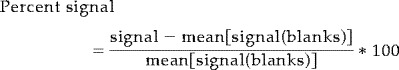
The first six images were discarded. Activation time courses were shifted individually for each subject by 4 or 6 sec (2 or 3 TRs respectively). One subject was excluded from the data analysis because of poor quality of fMRI data. A detailed description of the data analysis procedures and statistical analysis is given in Grill‐Spector et al. [1998a]. Briefly, preprocessing of the images was done using principal component analysis [Grill‐Spector et al., 1998a; Reyment and Joreskog, 1993] to remove drift and high‐frequency noise. Statistical maps were spatially smoothed using a Gaussian filter, and were obtained by regressing the data to an ideal box‐car time‐course. Time course of activation was extracted from selected regions. The percent signal change was calculated as the percent change from a blank baseline that is the mean signal of the blank epochs:
 |
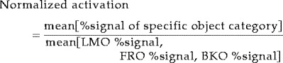
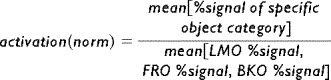
All epochs belonging to the same condition were averaged together to provide an average condition activation level (for example, Fig. 5). Error bars indicate standard error at each time point between recurrences of the condition. Normalized fMRI activation (Fig. 7) was calculated for each subject according to the mean activation over all the objects epochs (LMO, FRO, BKO):
 |
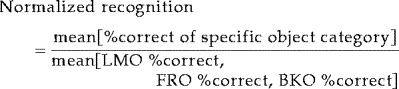
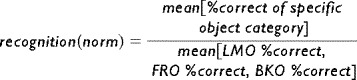
Normalized recognition performance (Fig. 7) was calculated for each subject according to the mean recognition over all the object categories (LMO, FRO, BKO):
 |
To visualize functional data on surface format in Talairach space (see below), four subjects underwent a detailed anatomical scan (T1 SPGR sequence) from which a 3D anatomical volume was created and allowed surface reconstruction (see below). The original functional data (12 2D EPI slices) of these four subjects was superimposed on the unfolded cortex after careful alignment of the EPI images to the 3D anatomical volume. The aligned functional data of each subject was then co‐registered into Talairach space coordinates.
Figure 5.

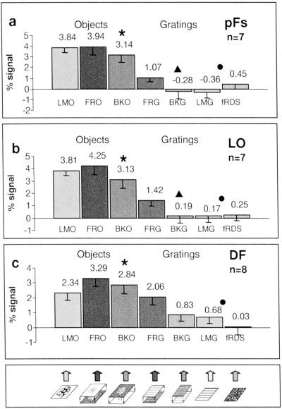
Recognition rates and activation levels of the different conditions. (a) Mean recognition performance (% correct). (b–d) Regions defined by their preferential activation to luminance‐defined objects vs. luminance‐defined gratings and noise (LMO > LMG and fRDS). (b) Posterior fusiform (pFs). (c) Lateral occipital (LO). (d) Dorsal foci (DF). (e,f) Regions in retinotopic areas were identified by their preferential visual activation to random dots compared to blank (FRO, BKO, FRG, BKG, and fRDS > blank), and by meridian mapping done separately. (e) V4/V8. (f) V1/V2. Circle denotes an unbiased, significantly higher value for stereo objects over stereo gratings, asterisk denotes an unbiased, significantly higher, value for “front”‐objects over “back”‐objects (for P‐values see Results). Values in (b–f) represent mean activation level across subjects over all the condition's epochs. Note the trend for preferential “front” over “back” activation (asterisk), particularly in the pFs.
Figure 7.
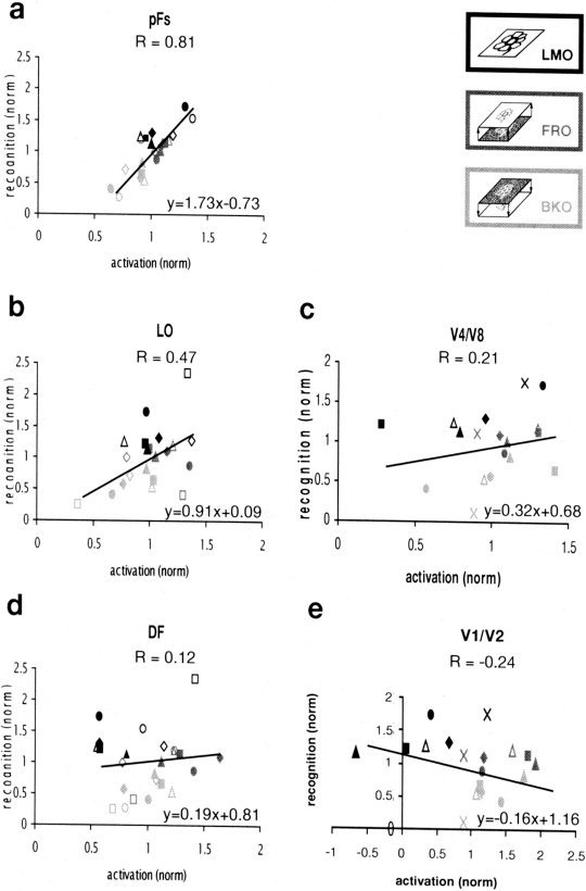
 |
 |
For surface reconstruction and normalization, the cortex was segmented, and flattened maps were produced using the Brainvoyager software Package (R. Goebel, Brain Innovation, Masstricht, Netherlands). Briefly, after the 3D anatomical volume was transformed into Talairach space, the white matter was segmented at the white matter/gray matter transition, using a grow‐region function. A smooth surface was aligned at the border, expanding slightly into the gray matter. The produced surface was then unfolded and cut along the calcarine sulcus for flattening. Talairach coordinates were determined for the centers of each ROI.
Definitions of ROI
Luminance‐object selective regions were defined solely based on their preferential activation to luminance‐defined objects compared to luminance‐defined gratings and noise (‘LMO > LMG and fRDS’ test) whereas the stereo‐defined epochs and blanks were ignored. For each individual subject only significant voxels (P < 0.01) were considered.
Stereo‐object selective regions were defined solely based on their preferential activation to stereo‐defined objects compared to stereo‐defined gratings (‘FRO and BKO > FRG and BKG’ test, P < 0.01) whereas the luminance‐defined epochs and blanks were ignored.
Areas V1/V2 and V4/V8 were identified by their preferential activation to RDS stimuli over blank (FRO, BKO, FRG, BKG and fRDS > blank) because they were not activated preferentially by the luminance objects [see also Grill‐Spector et al., 1998b].
RESULTS
The first question we addressed in the present study was: can ventral stream object areas utilize purely stereoscopic depth cues in the object recognition process? To answer this question we compared activation profiles to images of luminance‐defined, black on white, line drawings of objects (LMO, Fig. 1) with activation to the same line drawings generated by RDS (Stereo‐objects: FRO and BKO, Fig. 1). Note that the appearance of the stereo line drawings can be decoded only in binocular viewing, using stereo disparity cues, whereas monocular viewing reveals only a meaningless collection of dots (Fig. 2). Square‐wave gratings generated in black and white (LMG, Fig. 1) and the same gratings generated by RDS (FRG, BKG, Fig. 1) served as controls, because we have shown previously [Grill‐Spector et al., 1998a] that the LOC is activated preferentially to objects compared to gratings. Black and white RDS with zero disparity (fRDS) were also used as controls to rule out monocular activation by RDS.
Figure 2.
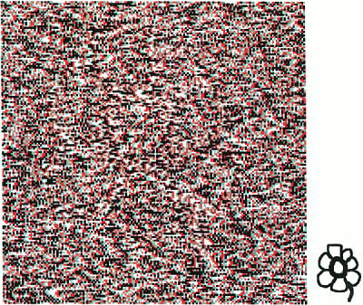
Illustration of the “Stereo Front” effect. Should be viewed with red‐green or red‐magenta glasses. Green on left eye, red on right eye creates a stereo “front” object (FRO). Red on left eye, green on right eye creates stereo “back” object (BKO). Small picture at lower right represents what should be seen (LMO). Note that the “front” object (green on left eye) is perceived much easier than the “back” object (green on right eye).
The second question we addressed was to what extent the fMRI signal was correlated with the ability to recognize objects. To answer this question we used a stereoscopic manipulation that profoundly affects recognition. We compared recognition rates and fMRI activation from the same stereoscopic images of line drawings created by RDS in two situations. In one, the objects appeared to “float” in front of the background (“front” objects, FRO, Fig. 1; for visualization see Fig. 2), and in the other they appeared to be “sunk” behind the background (“back” objects, BKO, Fig. 1; for visualization see Fig. 2). Note that previous studies [Fox and Patterson, 1981; Lehmkuhle and Fox, 1980] and our own psychophysical measurements (see below) reveal that the “front” object stimuli are much more recognizable than the “back” ones. We will refer to this phenomenon as the “Stereo Front” effect.
Convergence of stereoscopic and luminance cues in occipito‐temporal object‐related areas
To search for cortical regions activated by stereo‐defined objects we conducted a statistical correlation test looking for preferential activation to epochs of stereo‐defined objects compared to epochs of stereo‐defined gratings. This test highlighted voxels located in three main foci that were defined based on their location relative to retinotopic areas and anatomical criteria. The division between these object‐selective regions was done by anatomical criteria as described below. Figure 3 shows the location of these foci (red and blue) in a folded, inflated and unfolded formats (see also Fig. 4). The borders of retinotopic visual areas are indicated by dotted lines. The three main foci consisted of: a) Dorsal foci (DF), which included the intraparietal sulcus (DF2, Table I) and a region that overlaps area V3a (DF1, Table I); b) lateral occipital focus (LO), which lies lateral and posterior to MT, extending into the posterior inferotemporal sulcus and anterior to V4/V8; c) posterior fusiform (pFs) gyrus, located anterior and lateral to areas V4/V8 extending into the occipito‐temporal sulcus. LOC (LO and pFs) voxels were found anterior to orderly retinotopic areas throughout this study.
Figure 3.
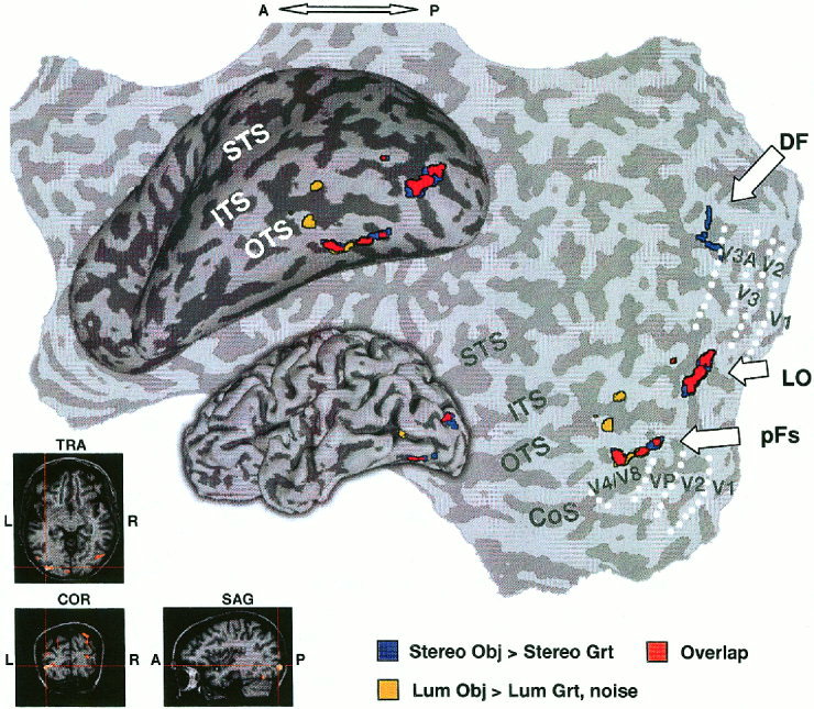
Comparison of object‐selective activation by stereo and luminance cues. Activation foci produced by stereo and luminance cues superimposed on folded, inflated, and unfolded left hemisphere of same subject. Sulci (dark gray), gyri (light gray). LO, lateral occipital; pFs, posterior fusiform; DF, dorsal foci; yellow, “luminance” objects‐selective voxels; blue, “stereo” objects‐selective voxels; red, overlap between them. Borders of retinotopic areas are indicated by white‐dotted lines. LO activation focus also shown on conventional anatomical images (lower left). Note the substantial overlap between stereo‐ and luminance‐defined object selective regions (red) in LOC (LO and pFs). STS, superior‐temporal sulcus; ITS, inferior‐temporal sulcus; OTS, occipito‐temporal sulcus; Cos, collateral sulcus. Note that only the posterior part of the brain was scanned.
Figure 4.
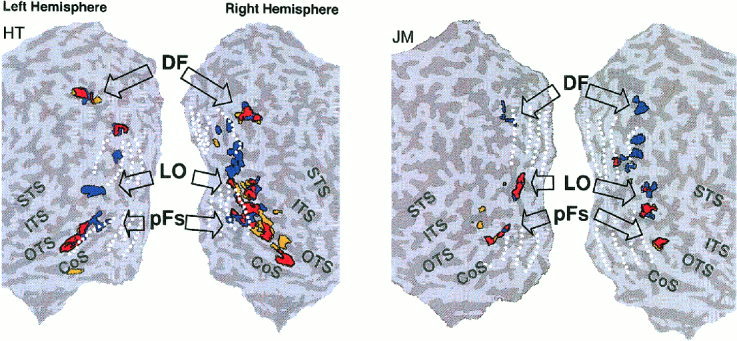
Object selective activation foci in four hemispheres. Activation foci shown on four unfolded hemispheres in two subjects to illustrate typical inter‐subject variability. Coloring of activation foci and notations similar to Figure 3. Note the overall similarity of the activation pattern across the different hemispheres and the substantial overlap (red) between stereo object‐selective voxels and luminance object‐selective voxels in LO and pFs. Note also that DF showed selectivity to stereo‐defined objects but without significant overlap.
Table I.
Talairach coordinates (n = 4)*
| Left hemisphere | Right hemisphere | |||||
|---|---|---|---|---|---|---|
| x | y | z | x | y | z | |
| LO | −41.0 ± 5.5 | −78.0 ± 7.2 | −8.8 ± 4.2 | 40.8 ± 6.1 | −68.0 ± 6.2 | −4.5 ± 2.6 |
| pFs | −33.3 ± 1.3 | −61.8 ± 8.5 | −21.5 ± 5.2 | 36.8 ± 5.0 | −59.5 ± 5.0 | −15.3 ± 2.6 |
| DF1 | −25.0 ± 7.3 | −82.3 ± 8.3 | 13.0 ± 14.7 | 30.3 ± 5.0 | −76.3 ± 7.7 | 13.8 ± 3.3 |
| DF2 | −22.0 ± 3.2 | −72.0 ± 11.9 | 31.0 ± 17.0 | 25.5 ± 1.3 | −72.5 ± 6.4 | 29.3 ± 6.6 |
Talairach coordinates of four subjects that participated in the experiment. LO, lateral occipital; pFs, posterior fusiform. Dorsal foci: DF1, probably V3A; DF2, intra‐parietal sulcus. Values represent mean ± SD in mm. Foci of two subjects appear in Figure 4. LO, pFs voxels selected by ‘luminance objects > luminance gratings and noise’ test. DF voxels selected by ‘stereo objects > stereo gratings’ test.
To explore how this activation pattern was related to the previously defined object‐related LOC, we compared it to voxels that were preferentially activated by luminance‐defined objects. The activated voxels were located in the LOC region as well as a few DF voxels (yellow and red in Figs. 3, 4). More importantly, there was a substantial overlap between the two maps (red in Figs. 3, 4), indicating that the same LOC voxels that were preferentially activated by luminance‐defined objects (LO, pFs in Table I), were also preferentially activated when objects were defined purely by stereoscopic cues (RDS). DF showed preferential activation to stereo‐defined objects but did not exhibit a high degree of overlap. From the six subjects having DF foci preferentially activated by luminance‐defined objects, there was an overlap with DF voxels preferentially activated by stereo‐defined objects in four subjects and this overlap was weaker than in LOC.
Figure 4 shows the results from four unfolded hemispheres. Note the substantial overlap that appears in the LOC in both the right and left hemispheres. Table I shows average Talairach coordinates [Talairach and Tournoux, 1988] of the activation foci from four subjects.
We analyzed the activation levels of the different conditions using two independent statistical tests. Each test served as an independent localizer [Kanwisher et al., 1997] in which we searched for voxels in one statistical test and looked for activity in other experimental conditions that were not included in that statistical test. In one test we searched for luminance‐object selective regions (preferring luminance objects over luminance gratings and noise) and in the other test we searched for stereo‐object selective regions (preferring stereo objects over stereo gratings). If indeed there was a convergence of stereo and luminance‐defined cues on the same voxels, then we would expect that voxels in luminance‐object selective regions would show enhanced activation to stereo objects over stereo gratings. Voxels in stereo‐object selective regions would show enhanced activation to luminance‐objects over luminance gratings and noise. Note that in both cases only one visual cue was used for defining the ROI, and the preferential activation to the other cue could occur only if the two cues converged on the same voxel population.
The results of this analysis are shown in Figure 5 (for luminance object selective regions) and in Figure 6 (for stereo object selective regions). As can be seen in Figure 5b–d, there was a clear enhancement for stereo objects over stereo gratings in the pFs, LO and DF regions, when they were defined purely by their preferential activation to luminance‐defined objects. Significance values for “stereo objects > stereo gratings” in these regions as obtained by Student's t‐test were: pFs, P < 2 × 10⁻⁵; LO, P < 0. 0002; DF, P < 0.05. Also, as can be seen in Figure 6, there was a clear enhancement for luminance objects over luminance gratings and noise in these regions, when they were defined purely by their preferential activation to stereo‐defined objects. Significance values for “luminance objects > luminance gratings and noise” in these regions as obtained by Student's t‐test were: pFs, P < 6 × 10⁻⁶; LO, P < 5 × 10⁻⁷; DF, P < 0.003. These results further confirm the object selective convergence of stereo and luminance cues in these regions and specifically in the LOC (LO and pFs).
Figure 6.
Activation levels of the different conditions in stereo‐defined, object‐selective regions. Same histograms as described in Figure 5, except the activations were obtained from regions that were highlighted by their preference to stereo‐defined objects compared to stereo‐defined gratings (FRO and BKO > FRG and BKG). Circle denotes an unbiased, significantly higher value for luminance objects over luminance gratings and noise, asterisk denotes a significantly higher value for “front”‐objects over “back”‐objects, triangle denotes the same for gratings (for P‐values see Results). Note that although the voxels were chosen by their stereo‐object selectivity, they manifest a similar selectivity for luminance‐defined objects (circle) indicating a clear convergence of object‐related stereo and luminance signals in the LOC.
Superior activation to “front” objects over “back” objects manifested mainly in the posterior fusiform gyrus
As noted earlier, the “front” vs. “back” stimuli differed greatly in their perceptual impact yet were quite similar in their local feature structure. To compare the activation level in the two conditions we defined regions of interest by an independent localizer [Kanwisher et al., 1997]. Object related regions were defined purely by their preference to luminance‐defined objects over luminance‐defined gratings and noise. Early visual areas were identified by a different localizer because we have shown previously [Grill‐Spector et al., 1998b] that they are not activated preferentially by luminance objects. For all these regions we examined the activation level and explored whether there was a significant preference to “front” objects over “back” objects by running a paired Student's t‐test for all such regions. The average activation levels of the different conditions are also shown in Figure 5. There was a preferential trend for “front” objects superiority over “back” objects in object related areas. The only region, however, that exhibited statistical significance for this contrast was pFs (Student's t‐test; 1‐tailed, paired probabilities: pFs, 0. 00314; LO, 0. 10997; DF, 0. 11062).
Similarly, in regions activated preferentially by stereo objects over stereo gratings (Fig. 6), there was a tendency for preferential activation to “front” compared to “back” objects, particularly in the pFs region. This preferential activation was significant for objects in the pFs (P < 0. 0004), LO (P < 0.03) and DF (P < 0.04). For gratings, a similar preferential activation for “front” vs. “back” gratings was found in the pFs and LO (P < 0.02). Note that in this statistical test “front” and “back” objects received the same weight.
Direct correlation between fMRI signal and recognition performance
To what extent was there a direct correlation between the recorded fMRI signal and the psychophysical performance of the subjects? To answer this question quantitatively, we measured psychophysical recognition performance of individual subjects to all the images of objects that were presented in the experiment. Measurements were taken inside the magnet immediately after the experiment. The results of these measurements can be seen in Figure 5a. Figure 7 shows, on a scatter plot, the relationship between normalized fMRI signal and normalized recognition performance for three object‐related regions as well as for V1/V2 and V4/V8. The highest correlation between normalized recognition performance and normalized signal was exhibited in the pFs (Fig. 7a). LO showed a medium correlation (Fig. 7b), whereas low correlation was exhibited in V4/V8, DF (Fig. 7c,d) and especially in V1/V2 (Fig. 7e).
Testing for priming effects
It could be argued that an important factor that may affect the activation to “front” and “back” objects is some sort of a priming effect, i.e., whether the subjects were exposed to the easily seen “front” or luminance‐defined objects before seeing the more difficult “back” objects. To rule out the possibility of priming from luminance‐defined objects, a luminance‐defined object (LMO) always appeared after both of its stereoscopic‐defined objects (FRO, BKO). We are aware, however, that this ordering might cause cross‐block adaptation effects. We expect that this effect will be minor because many images of objects were presented [Grill‐Spector and Malach, 2001], and consequently, we do not expect that this small change might affect our overall findings and conclusions. Also, two out of five of the “back” object epochs appeared before their corresponding “front” object epochs (so that 2/5 of the “back” objects had no possibility for priming effect).
To directly explore the possibility of priming between “front” and “back” objects, we analyzed the time course of activation separately for the following specific categories: “front” objects with priming (FRO+, appeared after their corresponding “back” objects), “front” objects without priming (FRO−), “back” objects with priming (BKO+, appeared after their corresponding “front” objects), and “back” objects without priming (BKO−). For the time‐course analysis we used an independent localizer. Voxels in the pFs, LO, and DF foci were defined solely based on their preferential activation to the luminance‐defined objects whereas the stereo‐defined epochs were ignored. Areas V1/V2 and V4/V8 were identified by a different independent localizer. The results of this analysis are shown both in Figure 5 and in Table II, which depicts the statistical significance of the priming effect according to a paired Student's t‐test. One can see that there was a small but significant priming enhancement for “back” objects in LO. This difference, however, was much smaller compared to the objects vs. gratings contrast.
Table II.
Priming effect: statistical significance*
| V1/V2 (n = 6) | V4/V8 (n = 6) | DF (n = 6) | LO (n = 6) | pFs(n = 7) | |
|---|---|---|---|---|---|
| BKO+ > BKO− | 0. 8384 | (0. 0582) | 0. 0715 | 0. 0439 | (0. 8057) |
| FRO+, BKO+ > FRO−, BKO− | (0. 2567) | (0. 3353) | 0. 3571 | 0. 6274 | (0. 5012) |
Student's t‐test (2‐tailed, paired) probabilities in the different anatomical areas. Values smaller than 0.05 indicate that fMRI activation with priming was significantly different than fMRI activation without priming (in bold). Values without parenthesis relate to enhanced activation with priming while values in parenthesis relate to reduced activation with priming. FRO+, BKO+, “front,” “back” objects with priming; FRO−, BKO−, “front,” “back” objects without priming. DF, dorsal foci; LO, lateral occipital; pFs, posterior fusiform. A significant enhancement for “back” objects was noticed only in LO. No significant difference was noticed for objects with priming vs. objects without priming in all areas. Recognition rates were not included because all recognition measurements were gathered after the fMRI experiment (with priming).
DISCUSSION
Stereoscopic object recognition
A central question in visual cortex research is to what extent visual cues such as color and motion are treated in a segregated manner by different visual areas, and to what extent high order areas combine signals of different modalities in performing visual tasks. We have demonstrated previously [Grill‐Spector et al., 1998a] that the LOC shows clear convergence of motion, texture and luminance cues when they are used to define objects. We extend this principle into the stereo domain, by showing that pure stereoscopic cues provide robust activation of the LOC and DF, provided that these cues are used to define visual objects.
A few single unit studies in monkeys' inferotemporal cortex, which is the presumptive homologue to humans' LOC [Malach et al., 1995], have investigated depth cues systematically. Janssen et al. [1999, 2000] have found sensitivity to stereo‐defined depth profiles and also to “convexity versus concavity”. This feature as an object descriptor is robust in the real world and might therefore be represented by TE columns [Tanaka, 1993, 2000]. Another recent study [Tanaka et al., 2001] has shown both sensitivity of IT neurons to shapes defined only by disparity cues, and also convergence of stereo, luminance and texture cues in single IT neurons. The stimuli used in this experiment were “flat” 2D shapes. This study supports our findings that stereo and luminance cues defining objects converge in high‐level object areas. Although the stimuli used in these experiments and ours were different (Janssen et al. [1999, 2000] used abstract 3D shape profiles defined by disparity gradients, Tanaka et al. [2001] used 8 “flat” 2D basic shapes defined by disparity, and in our experiment we used “flat” 2D objects defined by disparity), their findings are compatible with our results indicating a role for stereoscopic cues in activation of high‐level object areas.
Human neuroimaging studies [Gulyas and Roland, 1994; Mendola et al., 1999] have discussed the important role of V3A in depth processing and found foci that are anatomically similar to one of our dorsal foci (DF1). PET studies [Gulyas and Roland, 1994; Ptito et al., 1993] have shown stereoscopic activation starting in the primary and extrastriate visual cortex. Their stimuli, however, were simple shapes aimed at identifying basic stereoscopic processing, rather than object recognition. Mendola et al. [1999] showed fMRI activation to a stereo defined simple shape (square surface) in an area that extends to the lateral occipital region, although it seems that its main focus of activation was V3A and V7. They have not, however, explored whether this activation showed shape‐selectivity or was simply a reflection of general stereo processing. A recent fMRI study [Kourtzi and Kanwisher, 2000b] has shown indirectly stereo sensitivity in the LOC. Another recent fMRI study [Moore and Engel, 2001] reports on correlation between volume perception and the activation of LOC. It shows that 2D black on white images are perceived differently when primed for volume, and that only LOC activation is correlated with this change in perception.
Our study extends these findings in demonstrating shape‐selectivity for stereo‐defined patterns in human object‐areas, because we saw clear preferential activation to stereo‐defined objects compared to stereo‐defined gratings (Fig. 5). To our knowledge, the present work is the first demonstration that shape selective stereoscopic processing can affect the activation in human ventral stream non‐retinotopic object areas (LO, pFs).
Psychophysical “stereo front” effect
Previous psychophysical studies have emphasized the bias toward the frontal stereoscopic plane (“front effect”) [Fox and Patterson, 1981; Lehmkuhle and Fox, 1980]. They showed that for a fixed target position in depth, a stereoscopic target's recognition improved as the mask seemed further than the target (behind) and decreased when the mask was closer to the viewer. Nakayama et al. [1989] showed that when stereoscopic occluding bars appear in front of a face (as natural occluders appear), recognition performance is much higher than when they appear to be “sunk back.”
Why are the “front” line drawings more easily recognizable than the “back” ones? One possibility, related to a suggestion advanced by Nakayama et al. [Nakayama et al., 1989] is that, as in real world situation, boundary contours separating adjacent regions of an image are always assigned to the front, closer object. In our experiment, when the stereoscopic contours were sunk behind the surface, they were assigned to the background surface (that was perceived as closer to the observer) and thus the objects became difficult to perceive. Another related possibility is that natural objects are defined by solid and not by void. The “front” objects can be thought of as solid‐defined, whereas the “back” objects could be thought of void‐defined.
Relationship of fMRI Activation to Recognition Performance
To what extent is the activation by stereo‐defined objects really related to object recognition? One way to explore this issue is to relate the fMRI activation to recognition performance. We have demonstrated recently, using a backward masking paradigm [Grill‐Spector et al., 2000], that the correlation between recognition performance of subjects and fMRI signal was highest in the lateral occipital complex (LO and pFs). Other studies have also emphasized the correlation in this region between the ability to recognize objects and the fMRI activation [Bar et al., 2001; James et al., 2000].
In the present work we took advantage of the ability to change the recognizability of the stereo‐defined objects through the “stereo front” effect (see above). We used this manipulation of switching the local stereo cues to explore the relationship between fMRI activation and object recognition. Our results show that the activation by stereo‐defined objects in the LOC is correlated to recognition (Fig. 7a,b; see also Fig. 5a compared to Fig. 5b,c), especially in the more anterior part of the LOC, the pFs. This result is comparable with the backward masking results [Bar et al., 2001; Grill‐Spector et al., 2000]. Because the switch from the “front” to the “back” condition involved only a minor change in the local feature structure, our results point to possible involvement of high‐level stereo grouping in the LOC. It is also interesting in this respect that the more anterior part of the LOC, the pFs, showed the highest correlation. This provides further support to the possibility that the pFs may represent a higher‐level processing stage within the LOC [Grill‐Spector et al., 1999; Lerner et al., 2001].
Priming effects
Priming refers to changes in the ability to identify a stimulus as a function of a prior encounter with that stimulus [e.g., Schacter and Buckner, 1998]. We have not found a strong priming effect in our study (Table II). Our study, however, was designed to minimize such effects (see methods). Our behavioral results, which were all gathered after initial exposure during the MRI scan, were not substantially affected by priming, because the “back” objects were still recognized much worse (correct recognition: 39.81 ± 7.22% SEM) than the “front” objects (73.52 ± 9.14% SEM). Although we did not measure the recognition directly during the scan, we would expect priming to reduce the difference between “front” and “back” recognition, yet we see a two fold increase in sensitivity for the “front” condition after the scan.
Acknowledgements
This study was funded by JSMF 99‐28 CN‐QUA.05 and Israel Academy 8009 grants. We thank Michal Harel for the brain flattening procedure. We thank E. Okon for technical help.
REFERENCES
- Bar M, Tootell RB, Schacter D, Greve D, Fischl B, Mendola J, Rosen B, Dale A (2001): Cortical mechanisms specific to explicit visual object recognition. Neuron 29: 529–535. [DOI] [PubMed] [Google Scholar]
- DeAngelis GC, Newsome WT (1999): Organization of disparity‐selective neurons in macaque area MT. J Neurosci 19: 1398–1415. [DOI] [PMC free article] [PubMed] [Google Scholar]
- Fox R, Patterson R (1981): Depth separation and lateral interference. Percept Psychophys 30: 513–520. [DOI] [PubMed] [Google Scholar]
- Gilaie Dotan S, Ullman S, Kushnir T, Steinberg I, Malach R. (2000): Stereo Gestalt effects in human object related visual areas. Soc Neurosci Abstr 26: 1333. [Google Scholar]
- Grill‐Spector K, Kushnir T, Edelman S, Itzchak Y, Malach R (1998a): Cue‐invariant activation in object‐related areas of the human occipital lobe. Neuron 21: 191–202. [DOI] [PubMed] [Google Scholar]
- Grill‐Spector K, Kushnir T, Hendler T, Edelman S, Itzchak Y, Malach R (1998b): A sequence of object‐processing stages revealed by fMRI in the human occipital lobe. Hum Brain Mapp 6: 316–328. [DOI] [PMC free article] [PubMed] [Google Scholar]
- Grill‐Spector K, Kushnir T, Edelman S, Avidan G, Itzchak Y, Malach R (1999): Differential processing of objects under various viewing conditions in the human lateral occipital complex. Neuron 24: 187–203. [DOI] [PubMed] [Google Scholar]
- Grill‐Spector K, Kushnir T, Hendler T, Malach R (2000): The dynamics of object‐selective activation correlate with recognition performance in humans. Nat Neurosci 3: 837–843. [DOI] [PubMed] [Google Scholar]
- Grill‐Spector K, Malach R (2001): fMR‐adaptation: a tool for studying the functional properties of human cortical neurons. Acta Psychol (Amst) 107: 293–321. [DOI] [PubMed] [Google Scholar]
- Gulyas B, Roland PE (1994): Binocular disparity discrimination in human cerebral cortex: functional anatomy by positron emission tomography. Proc Natl Acad Sci USA 91: 1239–1243. [DOI] [PMC free article] [PubMed] [Google Scholar]
- James TW, Humphrey GK, Gati JS, Menon RS, Goodale MA (2000): The effects of visual object priming on brain activation before and after recognition. Curr Biol 10: 1017–1024. [DOI] [PubMed] [Google Scholar]
- Janssen P, Vogels R, Orban GA (1999): Macaque inferior temporal neurons are selective for disparity‐defined 3D shapes. Proc Natl Acad Sci USA 96: 8217–8222. [DOI] [PMC free article] [PubMed] [Google Scholar]
- Janssen P, Vogels R, Orban GA (2000): Three‐dimensional shape coding in inferior temporal cortex. Neuron 27: 385–397. [DOI] [PubMed] [Google Scholar]
- Julesz B (1971): Foundations of cyclopean perception. Chicago: University of Chicago Press. [Google Scholar]
- Kanwisher N, McDermott J, Chun MM (1997): The fusiform face area: a module in human extrastriate cortex specialized for face perception. J Neurosci 17: 4302–4311. [DOI] [PMC free article] [PubMed] [Google Scholar]
- Kourtzi Z, Kanwisher N (2000a): Cortical regions involved in perceiving object shape. J Neurosci 20: 3310–3318. [DOI] [PMC free article] [PubMed] [Google Scholar]
- Kourtzi Z, Kanwisher N (2000b): Processing of object structure versus contours in the human lateral occipital cortex. Soc Neurosci Abstr 26: 1332. [Google Scholar]
- Lehmkuhle S, Fox R (1980): Effect of depth separation on metacontrast masking. J Exp Psychol Hum Percept Perform 6: 605–621. [DOI] [PubMed] [Google Scholar]
- Lerner Y, Hendler T, Harel M, Malach R (2001): A hierarchical axis of object processing stages in the human visual cortex. Cereb Cortex 11: 287–297. [DOI] [PubMed] [Google Scholar]
- Livingstone M, Hubel D (1988): Segregation of form, color, movement, and depth: anatomy, physiology, and perception. Science 240: 740–749. [DOI] [PubMed] [Google Scholar]
- Logothetis NK, Sheinberg DL (1996): Visual object recognition. Annu Rev Neurosci 19: 577–621. [DOI] [PubMed] [Google Scholar]
- Malach R, Reppas JB, Benson RR, Kwong KK, Jiang H, Kennedy WA, Ledden PJ, Brady TJ, Rosen BR, Tootell RB (1995): Object‐related activity revealed by functional magnetic resonance imaging in human occipital cortex. Proc Natl Acad Sci USA 92: 8135–8139. [DOI] [PMC free article] [PubMed] [Google Scholar]
- Maunsell JH, Van Essen DC (1983): The connections of the middle temporal visual area (MT) and their relationship to a cortical hierarchy in the macaque monkey. J Neurosci 3: 2563–2586. [DOI] [PMC free article] [PubMed] [Google Scholar]
- Mendola JD, Dale AM, Fischl B, Liu AK, Tootell RBH (1999): The representation of illusory and real contours in human cortical visual areas revealed by functional magnetic resonance imaging. J Neurosci 19: 8560–8572. [DOI] [PMC free article] [PubMed] [Google Scholar]
- Moore C, and Engel, A (2001): Neural response to perception of volume in the lateral occipital complex. Neuron 29: 277–286. [DOI] [PubMed] [Google Scholar]
- Nakayama K, Shimojo S, Silverman GH (1989): Stereoscopic depth: its relation to image segmentation, grouping, and the recognition of occluded objects. Perception 18: 55–68. [DOI] [PubMed] [Google Scholar]
- Ptito A, Zatorre RJ, Petrides M, Frey S, Alivisatos B, Evans AC (1993): Localization and lateralization of stereoscopic processing in the human brain. Neuroreport 4: 1155–1158. [PubMed] [Google Scholar]
- Reyment R, Joreskog K (1993): Applied factor analysis in the natural sciences. Cambridge, MA: Cambridge University Press. [Google Scholar]
- Sary G, Vogels R, Orban GA (1993): Cue‐invariant shape selectivity of macaque inferior temporal neurons. Science 260: 995–997. [DOI] [PubMed] [Google Scholar]
- Schacter DL, Buckner RL (1998): On the relations among priming, conscious recollection, and intentional retrieval: evidence from neuroimaging research. Neurobiol Learn Mem 70: 284–303. [DOI] [PubMed] [Google Scholar]
- Talairach J, Tournoux P (1988): Co‐planar stereotaxic atlas of the human brain. New York: Thieme Medical Publishers. [Google Scholar]
- Tanaka H, Uka T, Yoshiyama K, Kato M, Fujita I (2001): Processing of shape defined by disparity in monkey inferior temporal cortex. J Neurophysiol 85: 735–744. [DOI] [PubMed] [Google Scholar]
- Tanaka K (1993): Neuronal mechanisms of object recognition. Science 262: 685–688. [DOI] [PubMed] [Google Scholar]
- Tanaka K (1997): Mechanisms of visual object recognition: monkey and human studies. Curr Opin Neurobiol 7: 523–529. [DOI] [PubMed] [Google Scholar]
- Tanaka K (2000): Curvature in depth for object recognition. Neuron Previews 27: 195–196. [DOI] [PubMed] [Google Scholar]