

Maxwell stress–activated shape-morphing liquid crystal elastomer actuators are efficient, fast, and forceful.
Abstract
Soft robotics may enable many new technologies in which humans and robots physically interact, yet the necessary high-performance soft actuators still do not exist. The optimal soft actuators need to be fast and forceful and have programmable shape changes. Furthermore, they should be energy efficient for untethered applications and easy to fabricate. Here, we combine desirable characteristics from two distinct active material systems: fast and highly efficient actuation from dielectric elastomers and directed shape programmability from liquid crystal elastomers. Via a top-down photoalignment method, we program molecular alignment and localized giant elastic anisotropy into the liquid crystal elastomers. The linearly actuated liquid crystal elastomer monoliths achieve strain rates over 120% per second with an energy conversion efficiency of 20% while moving loads over 700 times the elastomer weight. The electric actuation mechanism offers unprecedented opportunities toward miniaturization with shape programmability, efficiency, and more degrees of freedom for applications in soft robotics and beyond.
INTRODUCTION
The underlying rigid actuation mechanisms of traditional robotics, electric motors, or hydraulic and pneumatic actuators hinder robot miniaturization and, more importantly, robot use in human collaborative environments. Compliant actuators are the missing key to enabling robots to interface with humans (1). The ideal compliant soft actuators will have high efficiency, strength-to-weight ratio, work capacity, and shape programmability to perform complex functions. Like an artificial muscle, soft actuators with these properties would substantially advance technologies for potential applications in aerospace, robotics, medical devices, energy harvesting devices, and wearables (2–4). Among many soft actuators that have been explored, dielectric elastomers (DEs) appear promising and even outperform skeletal muscle in some aspects (5–8). Separately, liquid crystal elastomers (LCEs) have demonstrated reversible large mechanical deformation by light actuation and thermal actuation near the phase transition temperature (9, 10). Recent advances in photoalignment and microfabrication techniques have enabled preprogramming of liquid crystal alignment in microscopic regions for complex shape morphing (11, 12). However, both actuator types have their drawbacks: DE films need to be prestrained macroscopically (13) or require multistep fabrication methods, which make it difficult to program miniaturized actuators with local shape changing (14). Meanwhile, direct conversion of electrical energy to mechanical work using LCEs has, until now, remained limited because of the small strains generated (15–19). However, we demonstrate that the ability to pattern LCE molecules in a locally varying alignment, thus tailoring spatial variations of the mechanical compliance, enables more efficient DE actuators with preprogrammable degree and direction of actuation.
Typically, DE actuators function by the electrostatic attraction between two compliant electrodes coated on opposing sides of an isotropic DE to form a variable resistor-capacitor (Fig. 1A) (13). A high voltage applied to the compliant electrodes induces an electrostatic pressure, so-called Maxwell stress, and, hence, deforms the DE. The electrical actuation mechanism can result in a much higher operating efficiency (ratio of mechanical work to input electrical energy) and a higher actuation speed than those of LCEs (7, 8). Besides functioning as soft linear actuators, DE actuators could be applied to grippers, haptic devices, or optical devices, which, however, require complex shape change (6). Despite some impressive demonstrations, DE actuators have not yet gained widespread use in soft robotics partly because of the need for prestrain or the challenge of fabricating devices with complex deformation profiles (14). Overcoming these challenges and expanding the applications of DE actuators require material innovation for the next generation of high-performance DEs with shape programmability (20, 21).
Fig. 1. Device schematic, mechanical, and electrical characterization.
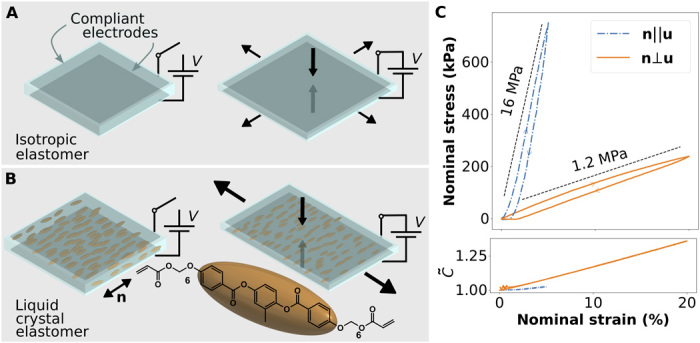
(A) Schematic of a traditional isotropic DE actuator in off and on states. (B) Schematic of a uniaxial aligned dielectric LCE actuator (DLCEA) in off and on states. Liquid crystal molecular alignment; the director, n, is indicated by a double-headed arrow and defines the stiffer direction of the LCE. When actuated by a voltage, V, the material thins and stretches perpendicular to the alignment greater than parallel to the director. (C) The DLCEA mechanical stress and normalized capacitance () response to strain over the DLCEA linear regime are characterized at a strain rate of 0.1% per second.
LCEs are rubbery polymers with anisotropic bulk properties imparted by their constituent molecular anisotropy. Most prior works on LCE actuation have focused on thermal or light-driven mechanisms. Heat or light temporarily disrupts the anisotropic molecular order, known as the director field (n), thereby creating internal stresses and anisotropic bulk deformation (10, 11, 18). The local LCE director field can be preprogrammed to create complex shape changes when actuated. However, light actuation is inefficient, and thermal actuation is both slow and inefficient; thus, they are poorly suited for applications that require high energy efficiency and fast actuation such as robotics. Direct electrical actuation of LCEs is a highly sought-after technology (17). A few previous studies have demonstrated electrical actuation of LCEs by coupling an electric field to the molecular dielectric anisotropy or sometimes to the intrinsic polarization of the LCE or LCE composite; thus, an electric field drives molecular reorientation to create bulk strains. However, these methods require elevated temperatures or use of carbon nanotubes to enhance the electric response; otherwise, only small actuation strains are produced at room temperature (15, 16, 22–24). In this work, we directly exploit the large mechanical anisotropy of LCEs without relying on molecular rotation during electric actuation. We further use recent advances in the patterning of LCE films to tailor the local anisotropic elasticity and Poisson’s ratios for highly efficient and shape-programmable DEs, which we refer to as a dielectric LCE actuator (DLCEA; Fig. 1B). By aligning LCE molecules in local domains, we achieve electric-driven actuation and shape morphing at room temperature and demonstrate large, fast, and forceful strains.
RESULTS
Uniaxially aligned DLCEA characterization
The LCE films are fabricated in a two-step process recently developed by some of the authors (25, 26). Briefly, an oligomer is synthesized before LCE film fabrication by a thiol-acrylate click reaction; a common diacrylate reactive liquid crystal monomer is chain-extended by Michael addition with a dithiol linker molecule. The exact component ratios, choice of monomer, and dithiol linker can all be tuned to adjust the specific mechanical properties of the final LCE film (26, 27). We produced large areas of a well-ordered uniaxial LCE (figs. S1 and S2) with giant elastic anisotropy (Fig. 1C). In all experiments, we actuated DLCEAs at room temperature and only in the linear regime of strains (fig. S3). We can also locally program the LCE director field by photoalignment to create a spatially programmed command surface and to locally orient the LCE director (28). Last, we applied compliant grease electrodes to both sides of the LCE film to create the DLCEA devices (fig. S4). Further details can be found in Materials and Methods.
To characterize the fundamental properties of DLCEAs, we first made monodomain, uniaxially aligned LCE films. The electrodes coated on uniaxial DLCEAs enable simultaneous measurement of capacitance and stress versus strain applied to the LCE film (Fig. 1C). When strains (u) are applied parallel to the director, n||u, the LCE is more than an order of magnitude stiffer than when strains are applied perpendicular to the director, n⊥u, which indicates a high degree of elastic anisotropy. Similarly, the difference in slope of the normalized capacitance between the DLCEA devices with different director orientation indicates anisotropy in Poisson’s ratio. The DLCEA capacitance is proportional to the area of the film coated by the electrode and inversely proportional to the film thickness. Thus, Poisson’s ratio anisotropy causes the film’s thickness and area to change at different rates depending on the direction of strain relative to the LCE director field (fig. S5A). Using a simplified finite element model, we find, for large elastic anisotropy, that a given Maxwell stress produces nearly two times the linear expansion strain observed in an isotropic material with a modulus equal to the soft direction (fig. S5B). Other works with similar LCE chemistry have observed one-dimensional (1D) translational crystallinity, which may explain the particularly large elastic anisotropy observed in this work (27, 29).
We then characterized uniaxial DLCEAs in isometric (constant strain; Fig. 2A) and isotonic (constant force; Fig. 2B) configurations. In isometric tests, we applied initial strains to DLCEA devices and allowed a relaxation period before the application of high voltages (fig. S6A). From the active stress reduction, we observe two relationships between the strain, the voltage applied, and active stresses, which fit with the model of Maxwell stress, pes ∝ V2/d2, where V is the applied voltage and d is the LCE film thickness. First, actuation at larger initial strains produces higher active nominal stress reductions; the isometric prestrain results in thinning of the LCE and, thus, higher Maxwell stress for a given voltage (Fig. 2A). With an LCE, it appears that additional strain thins the material at a rate fast enough to offset the increasing restoring force such that a given actuation voltage results in larger active stresses. We also observe that, for each fixed strain, the active nominal stress reduction during isometric tests increases quadratically with increasing voltage (fig. S6B). At the highest voltages tested, we measured peak active nominal stress reduction in excess of 50 kPa. However, for the device with the director, n||u, the active stresses are relatively much smaller because of the much higher modulus. When held with an isometric strain, the DLCEA behaves like a variable stiffness spring, and in the case of n⊥u, 5% initial strain, and 2 kV actuation voltage, the Maxwell stress–induced expansion of the LCE nearly compensates for the entirety of the isometric strain–induced stress. We also performed isopotential tests in which the DLCEA is strained under a constant voltage. These tests indicate the expected actuation stroke of a loaded DLCEA when a voltage is applied (fig. S7).
Fig. 2. Characterization of uniaxial DLCEA demonstrates the capabilities of a DLCEA actuator device.
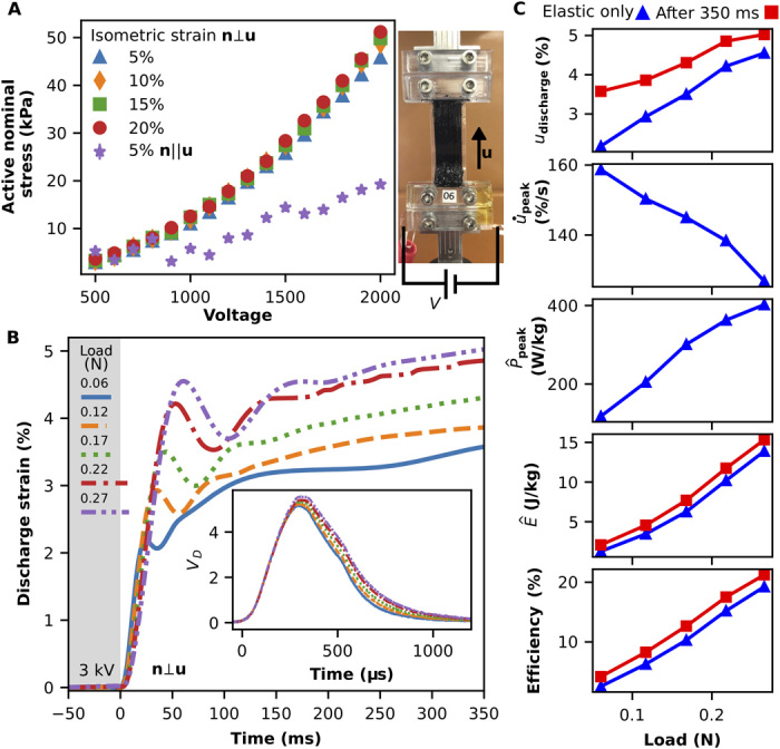
(A) Isometric (constant strain) tests. Measured active nominal stress reduction with various initial isometric strains (u) for devices assembled with the LCE director n⊥u and n‖u and a photograph of an assembled DLCEA device with n⊥u. (B) Isotonic (constant force) tests. Contractile discharge strain trajectories under various loads measured by a high-speed camera with actuation voltages of 3 kV. Inset: The corresponding measurements of electrical discharge. (C) Fundamental actuator characteristics are computed from the contraction trajectory and measurement of the discharge current found in (B), including strain (u), peak strain rate (), peak specific power (), specific energy (), and efficiency. Photo credits: Zoey S. Davidson.
Next, we take the same DLCEA and perform isotonic tests by suspending varying weights from the free end of the DLCEA to generate constant load forces and initial nominal strains, u (Fig. 2B and fig. S8). DLCEAs in the n||u configuration do not show an appreciable active strain at any initial loading for even the highest voltages tested because of their significantly higher elastic modulus (movie S1). However, DLCEAs with the n⊥u configuration exhibit fast active strains up to 5% with the application of 3 kV for the heaviest loading tested, 0.27 N, approximately 790 times the weight of the bare LCE film (35 mg). We perform isotonic contractile tests by abruptly discharging weighted DLCEA devices and capture the subsequent motion with high-speed video (fig. S8B and movie S2). With increasing load and initial strain, the DLCEA capacitance increases, which can be seen in the shifted discharge curves in the inset of Fig. 2B. In all cases, the electrical discharge time, approximately 1 ms, is much faster than that needed for the contraction of DLCEA, within 60 ms, which indicates that the system is currently limited by the viscoelastic properties of the LCE. We also observed significant viscous losses in the contractions that are apparent from the continued creeping contraction after the initial elastic response (fig. S8B). From the DLCEA contraction trajectory, we compute fundamental performance metrics both for the pure elastic response and for the extended creeping contraction (Fig. 2C and fig. S8C).
Complex programmable shape actuation
To achieve complex shape actuation, LCEs typically function by programming spatially varying in-plane contractile strain when heated above a phase transition. However, the DE actuation mechanism is not based on a heat induced phase transition, but generates in-plane expansion strains. Thus, boundary conditions play a significant role in determining the realized DLCEA shape change. To better understand the role of boundary conditions on DLCEAs, we performed a fundamental characterization of the buckling effect caused by the elastomer’s expansion between fixed boundaries (Fig. 3, A and B, and movie S3). The buckling amplitude increases with increasing voltage and, at 2.5 kV, creates out-of-plane peak-to-peak strokes greater than 1800% of the LCE film thickness of approximately 80 μm corresponding to a linear strain of approximately 5% (Fig. 3C and fig. S9A). Actuation speed is another important characteristic for potential DLCEA applications. We applied a sinusoidally varying 1-kV potential to measure the change in actuation amplitude as a function of the applied frequency (Fig. 3D and fig. S9B). The actuation amplitude decays exponentially with the frequency but is still a perceivable 50 μm at 30 Hz and 1 kV.
Fig. 3. Uniaxial out-of-plane buckling DLCEA.
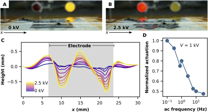
(A) Off and (B) on states of a uniaxial DLCEA device with fixed boundary condition. Expansion along the soft direction creates out-of-plane buckling, which displaces a fine thread held taut across the surface. (C) Experimental measurement of buckling as a function of the applied voltage. (D) Frequency response of buckling uniaxial DLCEA at 1 kV. The 0.1-Hz actuation amplitude is approximately 130 μm.
Photo credits: Zoey S. Davidson.
We designed spatially varying LCE director configurations, aiming to demonstrate the ability to preprogram complex patterns in 2D, followed by electrical actuation of the films into 3D forms (11, 25). Depending on the programmed director field, the LCE film buckles out of plane with locally positive (Fig. 4A) or negative Gaussian curvature (Fig. 4B). These shapes are often called cones and anti-cones, and the theory describing this form of deformation in elastic media was previously described by Modes et al. (30). We understand these shape changes by considering a simplified model of an anisotropic DE made from stiff concentric rings embedded in a soft elastomer (31). These rings prevent expansion along the rings but allow expansion in the radial direction leading to a frustration and out-of-plane buckling. A similar argument holds for radial stiff elements. The double-headed red arrows in Fig. 4 (A and B) indicate the soft expansion directions. We created a pixelated array of topological defects by spatially programming light polarization with a pattern of linear film polarizers (Fig. 4C) to locally orient the LCE director as in Fig. 4D. The director forms a lattice of radial and azimuthal defect types that, when electrically actuated, buckle out of plane because of incompatible in-plane strains (Fig. 4E and movie S4). We measured the height of the DLCEA surface in the discharged (0 V) and actuated (2.5 kV; Fig. 4F) states. To do so, we stably held the device in its actuated shape at 2.5 kV for more than 3 hours while drawing less than 1 μA, confirming its high stability and low power consumption. The locally programmed height change and the accompanying formation of Gaussian curvatures are clearly visible from the circular traces enclosing the central radial defect type (Fig. 4G). The out-of-plane buckling creates peak-to-peak height differences of over 1600 μm, a 2000% growth from the initial film thickness of approximately 80 μm corresponding to a 22% areal strain. The lower right corner of the actuated DLCEA in Fig. 4F shows that the defects could buckle both up and down.
Fig. 4. Pixelated DLCEA.
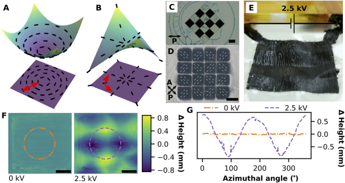
Programmed shape actuation, such as a dimple pattern deformation, is possible by patterning the director configuration into an azimuthal-radial defect lattice. (A) Azimuthal defect types deform into a cone with locally positive Gaussian curvature, and (B) radial defect types deform into an anti-cone with locally negative (saddle-like) Gaussian curvature. In (A) and (B), the double-headed red arrows indicate the soft direction. (C) The defects are patterned using a pixelated array of polarizing films with the designed local orientations. (D) Viewed through crossed polarizers, the fabricated LCE film has pixelated uniaxial alignment, indicated by dashed white lines, forming a defect lattice. (E) When charged to 2.5 kV, there is a large visible deformation of the surface. (F) The profilometry measured height map of the grease-covered LCE is nearly flat with no charge and varies over 1.6 mm when charged to 2.5 kV. The dash-dot and dash circles in (F) are traces of height depicted in (G). The change from approximately constant height to a sinusoidally varying height indicates a change in sign of the local Gaussian curvature. Scale bars, 4 mm. Photo credits: Zoey S. Davidson.
DISCUSSION
When using the DLCEA as a linear actuator, we expect larger anisotropy in Poisson’s ratio to produce higher efficiency and require lower electric fields for actuation compared to a similar isotropic material (32). Compared to other LCE actuators, the actuation efficiency of approximately 20% reported here is remarkable; to our knowledge, actuation efficiency in LCEs has not been reported before owing to their low energy conversion efficiency, which we estimate, for example, to be less than 0.001% in a thermally actuated LCE according to (18). Note that this estimate is based on the initial stroke only; a constant current is needed to maintain LCE in the contracted state. Furthermore, our DLCEA efficiency compares favorably to a recent example of an isotropic DE actuator with highly optimized electrodes, reporting 1.5% efficiency (7). We expect that reducing viscous loss and creep, indicated here by the hysteresis loop in Fig. 1C and extended contraction in Fig. 2B, will further improve the situation for fast and efficient DLCEAs.
We believe that the demonstrated high efficiency reported in our system is due to the anisotropy of the elastic modulus and Poisson’s ratio. Generally speaking, elastomers are volume conserving; thus, extension in one direction causes a contraction in the other directions. However, the contraction in LCE films is greater perpendicular to the director. In other words, when an LCE film is strained perpendicular to the director, it contracts in thickness, which is also perpendicular to the director, and thus faster than the contraction in width that is parallel to the director. When strained parallel to the director, the LCE contracts equally in both thickness and width (assuming that the cross section is isotropic). It is worth mentioning that this last point is not certain: As mentioned previously, 1D translation crystallinity is common in this class of LCE (27, 29). In particular, the 1D crystal planes may be at some angle to the LCE director, thus breaking the symmetry informing the assumption of equal contraction in width and thickness when straining parallel to the director. Tuning this 1D crystallinity may play an important role in further improving the linear actuation capabilities of DLCEAs.
To further illuminate the advantages of elastic anisotropy, we consider a simplified DE model with a nearly volume-conserving elastomer material having large Poisson’s ratio anisotropy and under no load (see fig. S5). In this model, nearly all compression strain due to the Maxwell stress creates an extension strain in the soft direction of the elastomer. In other words, the Maxwell strain through the thickness of the material, uz = Pes/Ez, results in strain uy and nearly no strain ux. In an isotropic elastomer, the same Maxwell strain would result in only half as much strain because the volume-conserving strain would be split evenly into ux and uy. For linear actuators, this is the first advantage of a DLCEA; the actuation voltage needed to achieve a given strain is reduced. The second advantage of anisotropy to linear actuators comes from energetic considerations of the same system. The elastic energy density of deformation is quadratic in strain; thus, in the simplified model presented here, there will be no energy component from strains in the x direction. Furthermore, for a given desired linear extensional strain, the input electric field energy (∝ V2/d2) will also be less because the required Maxwell strain is smaller than in an isotropic DE. Thus, an anisotropic DE actuator can achieve an equivalent strain as an isotropic DE linear actuator, but with higher efficiency. Both the no-load and perfect uniaxial elastomer assumptions may be relaxed, and viscoelastic effects may be added to build a more complete model.
The material Poisson’s ratio anisotropy is also an important feature for enabling programmed shape change actuation. The actuated (compressed) LCE transversely expands anisotropically to create the observed shape changes. Although, in principle, the buckled shape of the DLCEA is multistable, we only ever observe a single actuated state for each sample (11). We hypothesize that the symmetry that would enable multistability is likely broken by gravity during the tests or by uneven photocrosslinking of LCE films during device fabrication. Nevertheless, our demonstration of local changes in the Gaussian curvature indicates that our method can be potentially generalized to realize a large variety of programmable shape changes (30). In addition to programming in-plane director orientations, it is also possible to program the LCE director orientation along the film thickness. As seen in fig. S10, we have assembled DLCEAs with a twisted LCE configuration where the director rotates by nearly 90° from the top to the bottom surface. When an electric field is applied, the twisted DLCEA produces twisting motions where the magnitude depends on the LCE geometry in addition to the material’s intrinsic properties (33).
CONCLUSION
Here, by combining the desirable characteristics of DEs and LCEs in a single material platform, we demonstrate superior actuation performance from electrically actuated DLCEAs, including high energy conversion efficiency (20%), high actuation speed (120% per second), and programmable shape change from 2D to 3D with more than 1800% out-of-plane stroke. To achieve larger actuation forces, multilayer DLCEA stacks could be an option, as demonstrated in LCE and DE multilayer stacks (7, 34), although it would require the development of an alternative soft electrode. Furthermore, even more general shape changes, i.e., nonlocal Gaussian curvature, may be realized by spatially programming both the LCE alignment and local cross-linking density.
Insights into the integration of active materials with top-down microfabrication techniques and electroactuation mechanism presented here could offer exciting opportunities when coupling DLCEAs with 3D printing, origami and kirigami actuation strategies, and distributed control systems toward creating multifunctional soft robots in a scalable fashion at a low material and build cost. The electroactuation mechanism can also be applied to other technologies, including energy harvesting and storage, medical devices, wearable technology, and aerospace. Furthermore, fast and dynamic modulation could be useful in displays and optical applications.
MATERIALS AND METHODS
Materials
1,5-Pentanedithiol (1,5-PDT; >99%), 1,8-diazabicycloundec-7-ene (DBU), butylatedhydroxytoluene (BHT), and magnesium sulfate (MgSO4; anhydrous powder) were purchased from Sigma-Aldrich and used as received. Hydrochloric acid (HCl), dimethylformamide (DMF), and dichloromethane (DCM) were purchased from Fischer Scientific. The photoinitiator 2,2-dimethoxy-2-phenylacetophenone (DMPA) was purchased from Toronto Research Chemicals. Brilliant Yellow (BY) was purchased from Tokyo Chemical Industry. The liquid crystal monomer, 1,4-bis-[4-(6-acryloyloxy-hexyloxy)benzoyloxy]-2-methylbenzene (RM82; >95%), was purchased from Wilshire Technologies Inc. and used without further purification. Conductive carbon grease, NyoGel 756G, was purchased from Newgate Simms.
LCE oligomer synthesis
We fabricated LCE films in a two-step process recently developed by some of the authors (25, 26). An oligomer was synthesized before LCE film fabrication by a thiol-acrylate click reaction; the reactive liquid crystal monomer RM82 was chain-extended by Michael addition with 1,5-PDT. In a typical synthesis, 12.5 g of RM82 was mixed with 5.06 g of 1,5-PDT in 120 ml of DCM with three drops of DBU catalyst. After 16 hours of stirring at room temperature, the solution was rinsed in a separation funnel with 1 M HCl, 0.1 M HCl, and deionized water successively. The DCM-product mixture was then dried with 25 g of MgSO4 for 30 min, which was then filtered. BHT (50 mg) was added to the clear DCM and product mixture before rotary evaporation and direct vacuum until a thick white oligomer remained. The oligomer was stored at −30°C for up to 2 months.
Substrate preparation
Glass slides, typically 5 cm by 5 cm and 8 cm by 10 cm, were cleaned in an ultrasound bath with deionized water, isopropanol, and acetone. Next, the slides were dried with nitrogen and then treated by oxygen plasma. A mixture of 1 weight % BY dissolved in DMF was spin-coated onto the slides and then dried on a hot plate at 120°C. Spacers cut from polyimide or Mylar plastic, with thicknesses of 65 or 75 μm, were placed along the edges on one of the BY coat sides of the glass slides; then, two slides were placed with the BY-coated faces toward each other. Large paper clips held the slides together with a polarizer film placed on one side. A custom 447-nm light-emitting diode (LED) light source was used to illuminate the BY-coated glass through the polarizer film, thereby photo-programming the BY molecule orientations. To program locally varying Gaussian curvature, the polarizer film was cut into pixels and then reassembled by hand on a glass slide with the desired orientations (see Fig. 4C). The thin layer of BY molecules rearranged perpendicular to the incident light polarization to create a spatially photo-programmed command surface that then locally oriented the LCE director (28).
LCE fabrication and characterization
The previously prepared oligomer was melted together with additional RM82 and a small amount of photoinitiator to cross-link the oligomer chains into an elastomer network. In more detail, the LCE oligomer and an additional RM82 LCE monomer were melted together in 1:1 molar ratio, assuming that the oligomer consists purely of chains of single-unit length RM82 capped by 1,5-PDT on both ends (26). Thus, the mixture consisted of excess thiol groups, which were likely responsible for a significant portion of the final LCE viscous losses (see the section Uniaxially aligned DLCEA characterization), but this sparse cross-linking also promoted softness necessary to achieve larger actuation strains. The melt was mixed for only 2 to 3 min at 120°C and then degassed for approximately 3 min in a vacuum oven at 90°C. One weight percent DMPA was added and carefully stirred in so as not to reintroduce air bubbles.
The isotropic LCE melt was then poured onto the BY-coated glass at 80°C and then carefully sandwiched with a second hot BY-coated glass substrate. The BY-LCE-BY sandwich was cooled into the aligned (nematic) phase, approximately 73°C, and then gradually cooled to room temperature during which time it aligned with the spatial programming imparted by the BY coating, and the defects arising from the phase transition were annealed. Once the LCE cools to room temperature, it was cured in ultraviolet light with an OmniCure S2000 arc source. After exposure to ultraviolet light polymerized the LCE in its programmed state, we immersed the BY-LCE-BY sandwich in water to release the LCE from the BY-coated glass substrates.
The final LCE film thickness was confirmed by confocal laser profilometry from regions cut to make actuators (described below). Good alignment and few defects in the LCE are essential characteristics of the film to impart the largest possible elastic anisotropy and achieve optimal materials properties. The high contrast between the orientations of the LCE between crossed polarizers is visible in fig. S1.
After sheets of LCE were separated from the glass substrates, they were rinsed in water to remove residual BY and dried with nitrogen. The LCE sheets were placed back on glass substrates and carefully inspected to identify the defect and bubble-free regions for the fabrication of DLCEA devices. For uniaxial DLCEA devices, the cleanest identified regions were cut into rectangular pieces typically 14 mm by 34 mm with a typical weight of 35 mg. This size film was chosen for ease of handling and for the electrical actuation constraints described below. Smaller neighboring regions, 20 mm by 5 mm, were used to initially characterize the stress-strain behavior of the LCE and the large strain behavior.
The edges of the laser-cut regions on the larger film were then inspected by laser confocal interferometry (KEYENCE VK-X210) to confirm the as-fabricated height of the LCE films. We found that nominally 65-μm Kapton produces approximately 70-μm LCE films and that nominally 75-μm Mylar produces approximately 83-μm LCE films. The thicknesses may vary by as much as ±10% across the as-produced LCE sheet (fig. S2).
DLCEA fabrication
In the next step of DLCEA fabrication (fig. S4), we attached compliant electrodes to both sides of the LCE film using an electrically conductive carbon grease, NyoGel 756G, frequently used in other DE systems (35). To apply the carbon grease, the LCE was first clamped in 3D-printed plastic clips with copper tape leads designed to facilitate attaching the device to the equipment used for tests described below and in the section Uniaxially aligned DLCEA characterization. Some degree of misalignment in the clamping process was unavoidable. The clipped LCE was held in a laser-cut Plexiglas assembly jig and masked with a low-adhesive removable tape placed around the edges of the LCE film. The masking adhesive tape created a border region at the LCE edges with no electrode grease, which served to prevent shorting of the device during actuation at high voltages. A 2-mm gap around the edges was found to be sufficient to prevent shorting at the voltages tested (see Fig. 2A). The grease was applied by painting with a swab applicator, and excess was removed with a straight paper edge. The entire Plexiglas jig with LCE film was weighed before and after application of grease electrodes to find the grease weight, which was typically 30 mg in total for both electrodes of the DLCEA. Other high-conductivity electrode materials can achieve better performance while adding much less weight and cross-sectional area (7); alternative electrode materials will be studied in future studies of these actuators.
Poisson’s ratio anisotropy and DLCEA isometric and isopotential tests
Throughout this work, we tested and actuated DLCEAs at room temperature and only in the linear regime where strains do not induce reorientation of the LCE director. We typically found the onset of soft mode deformation (director reorientation) at a critical strain of 45 to 50% for n⊥u as in fig. S3.
We characterized laser-cut uniaxial DLCEAs mechanically and electrically (Fig. 1C and fig. S2). Tensile tests were performed in a TA Instruments DHR3, and simultaneous capacitance measurements were made with a Hameg 8118 LCR meter. Typically, the uniaxial DLCEAs fabricated with 65-μm spacers and electrodes coated on both sides with an area of 1 cm by 3 cm have a zero strain capacitance of approximately 300 pF. We observed a dependence between the rate of capacitance growth and the direction of the tensile strain of the LCE film relative to the director. The capacitance of DLCEAs strained perpendicular to the director grew faster than those strained parallel to the director. We can model how strains affect the DLCEA capacitance.
The capacitance of a parallel-plate capacitor (or a DLCEA) is
where ϵ0 is the permittivity of free space and ϵ⊥ is the relative permittivity perpendicular to the liquid crystal director (note that the reactive mesogen used in this work, RM82, is known to have a negative dielectric anisotropy, i.e., ϵ⊥ > ϵ‖). The rectangular area covered by the electrode is A = Sx × Sy, and the film thickness is d (see fig. S5 for the schematic and coordinate system). When the DLCEA is strained by uy (perpendicular to the director), the thickness decreases uz = − uyνyz and the width along x decreases ux = −uyνyx. The thickness and area become (1 + uz)d = (1 − uyνyz)d and (1 + uy)Sy(1 + ux)Sx = (1 + uy)(1 − uyνyx)A, respectively. Thus, the capacitance becomes
We next normalize by the capacitance at zero strain and then Taylor expand for small strains, i.e., to only the linear term
From the system symmetry and inserting into this equation the relationship between the mechanical anisotropy, Ey/νyx = Ex/νxy, and the assumption that vxy = 0.5, we obtained values for νyx ≈ 0.04 and νyz ≈ 0.84. Taken with the measured values of the elastic moduli (Fig. 1C), Ex and Ey, the stiffness tensor was fully defined. These values indicated that the LCE was unexpectedly compressible. However, this was unlikely and due to at least three factors: The capacitance Q factor decreased from 32 to 22 at 20% strain, and slight prestrains were unavoidable in measuring the moduli, Ex and Ey, of the LCE. These are in addition to the possibility of partially crystalline ordering (smectic C phase) as mentioned in the text. Together, these factors lead to an error that may account for the apparent compressibility.
Isometric tests were performed by quasistatically increasing applied voltages to prestrained samples. Following capacitance measurements, the DLCEA still clamped in the rheometer was strained to a fixed amount (5, 10, 15, and 20%) and then allowed to relax for a period until the creep in measured stress was much smaller than the induced stress (fig. S6A). The actuation voltage (Heinzinger LNC-10 kV) was increased 100 V every 15 s starting from 500 V. The middle 5 s of each period was sampled to measure the active change in stress due to the applied voltage. The log-active nominal stress reduction versus log-voltage relationship for all isometric strains had a slope of 2.0 (fig. S6B), following the relationship given by the Maxwell stress equation.
Isopotential tests were performed by straining the DLCEA first with no applied voltage, and then 2 kV was applied (fig. S7). The difference in induced stress between the 0- and 2-kV curves indicated the expected stroke when the DLCEA was operated as an actuator under a constant load.
DLCEA isotonic tests
To characterize the fundamental properties of the LCE as a muscle-like actuator, we performed tests on DLCEAs strained by a constant gravitational load, Fg. Weights hung from the DLCEA induced an initial strain that thins the material, thus aiding in larger actuation for higher initial loadings. When a voltage was applied to the DLCEA with n ⊥ Fg, the system adopted a new length due to the changed elastic response of the LCE. The LCE was strain stiffening, so the weight stopped when the forces balanced; however, after an initial elastic response, the DLCEA continued to creep because of the viscoelastic properties of the LCE. Gradually, the strain increased until it eventually reached a steady state. After some time, an electrical short path was provided to the electrodes of the DLCEA by a custom switching mechanism. The DLCEA was thus discharged and abruptly contracted elastically and then continued to further contract slowly again owing to the viscoelasticity (Fig. 2 and fig. S8). In the case of n‖Fg, there is no appreciable actuation along the loading direction because of the substantially higher stiffness (movie S1); therefore, no further tests were conducted on this configuration of DLCEA.
Simultaneously with the actuation, a high-speed camera (Vision Research v641) was hand-triggered. For the contraction data presented in Fig. 2B, the camera captured at 1400 frames per second. The video frame during which the high voltage was switched was identified by a pair of LEDs triggered by the same solid-state relay as the high-voltage switches. The discharge current was measured across a resistor divider pair in series with the DLCEA using an oscilloscope (Tektronix MDO4024C). A schematic of the high-voltage switching mechanism used to measure discharge current by reading the voltage, VD, across a known resistor, RD, is shown in fig. S8A. The actuation also depended on the applied voltages, and for each load, voltages of 2, 2.5, and 3 kV were tested on the same DLCEA (fig. S8C).
Video data from the contractile tests were tracked with Tracker Video Analysis (36) and then analyzed using custom Python scripts. In these tests, the high voltage was switched on for approximately 20 s before discharge so that the DLCEA would reach its actuated stable rest length. Initial distances were marked by hand in Tracker Analysis and then compared to known component sizes to compute distances and, subsequently, energy, power, and efficiency measurements. Oscilloscope data were also analyzed using custom Python code. A baseline capacitive charge was subtracted from the measured discharge by measuring the discharge with no DLCEA attached to the switch; each meter of high-voltage cable has a capacitance of approximately 100 pF.
The mechanical work done by the actuator while discharging was computed from the mass of the attached load, mL, and the displacement found by high-speed video, i.e., Wmech = mLgΔh, where g is the gravitational acceleration, 9.8 m/s2, and Δh is the displacement of the mass. The electrical energy input to the system, , was found by integrating the discharge current measured as a voltage, VD, over the known resistor, RD, and multiplying by the applied voltage (e.g., 3 kV). Last, the efficiency was computed from the ratio of these energies, Wmech/Wel.
Finite element simulations of the effect of Poisson’s ratio anisotropy
The finite element simulations were carried out using the Structural Mechanics Module of COMSOL Multiphysics 5.3a (COMSOL, 2008). Several mesh refinement steps were performed to guarantee convergence of the results. For the no-load simulations of DLCEA (fig. S5B), the LCE film was modeled as a thin anisotropic sheet (width, 14 mm; length, 30 mm) with an initial thickness of 80 μm. The compliance and stiffness matrices describing the anisotropic material with Voigt notation were computed using five independent elastic constants
where the following relations are valid assuming that “1” is x, i.e., along the nematic director
To demonstrate the effect of anisotropy on the performance of the actuator, we swept the value of E11 from 1 to 20 MPa while assuming Poisson’s ratios v12 = 0.5 and ν23 = 0.9 − ν21 and shear modulus (with the assumption that Young’s modulus and Bulk modulus are equal). The geometric boundary condition was defined as one-side clamped. The normal pressure load (100 kPa, as a representative of Maxwell stress) was applied to the top side of the LCE sheet by considering the margin of the electrodes as 2 mm, and a roller boundary condition was set to the bottom side of the LCE. A constant force was applied to the free edge of the LCE beam, opposite to the clamped edge, to induce deflection and simulated a gravitational load.
Efficiency comparison to thermal LCE actuation
In the work by Petsch et al. (18), a thin wire heater was embedded inside an aligned LCE. When heated, the device contracted along its aligned direction. The reported 90% contraction response time in that work was between 20 and 30 s. In the example reported in the text, they achieved a 1.85-mm stroke with a 2.25-g test load and 430 mW of input power. The stroke efficiency then is
or about 0.0005% for the stroke only. To maintain that stroke, a constant current must be applied.
Uniaxially buckling DLCEA and frequency response characterization
A uniaxial LCE film was constrained at its edges by a laser-cut Plexiglas frame. The film was carefully placed on top of the frame so as not to induce prestrain or leave any slack. A central square carbon grease electrode was painted onto the film on both sides through a low-adhesive removable tape mask. The in-plane length of the film grew along the soft direction, but because of the fixed boundary conditions, it created a buckled wrinkling pattern. The height of the wrinkle pattern was measured by laser confocal profilometry in the off state and every 250 V starting from 500 V to 2.5 kV. In the 2.5-kV activated state, the out-of-plane peak-to-peak stroke was 1.47 mm or 1800% of the LCE film thickness, which was approximately 80 μm.
To determine the frequency response of the uniaxial buckling DLCEA, we applied a sinusoidally varying 1 kV supplied by a Physik Instrumente E-107 piezo high-voltage amplifier. The input signal was generated by a function generator (Tektronix). The motion of the DLCEA membrane was observed by a Thorlabs Telesto optical coherence tomography microscope. The DLCEA film maximum height was first found manually in the dc on state and subsequently observed in the same location for various frequencies (Fig. 3D and fig. S9B).
Programmed buckling of DLCEA
The defect array was achieved by programming light polarization from laser-cut squares of a linear polarizer film that was stitched back into the desired grid on a glass slide using NOA65 ultraviolet curing glue. The stitched pieces of polarizing squares were not perfectly beside each other because of imperfections in the laser-cutting step and difficulty in manual stitching. However, the unaligned boundaries between aligned regions in the LCE film were small and did not apparently affect the actuation response.
Similar to the uniaxial buckling, after fabrication of the LCE and removing it from the BY-coated glass slides, we fixed the LCE film to a laser-cut Plexiglas frame and covered the programmed region with electrically conductive carbon grease. The programmed region was easily distinguished under ambient lighting from the surrounding areas because of the mismatch in the index of refraction between isotropic and well-aligned regions. The buckled shape of the film was measured by a KEYENCE laser profilometer (VK-X210) with a 10× objective set to ultrahigh-speed z scans with a 4-μm pitch. The observed area was a stitched image of many individual images.
Supplementary Material
Acknowledgments
We thank M. Millard, S. W. Heim, and members of the Physical Intelligence Department for helpful discussions and J. Lampart for construction of the high-voltage switching circuit. Funding: Z.S.D. and Y.G. were supported by the Alexander von Humboldt Foundation. H.S. was supported by the Natural Sciences and Engineering Research Council of Canada (NSERC). S.Y. acknowledges partial support from National Science Foundation (NSF)/EFRI-ODISSEI grant no. EFRI-1331583. A.A., L.H., and M.S. were supported by the Max Planck Society. Author contributions: Z.S.D. and H.S. conceived the research. Z.S.D. performed all experiments with assistance from H.S., A.A., Y.G., L.H., and Y.X. A.A. performed the simulations. Z.S.D. performed all analysis with assistance from H.S., A.A., S.Y., and M.S. Z.S.D. wrote the manuscript. All authors edited the manuscript. Competing interests: The authors declare that they have no competing interests. Data and materials availability: All data needed to evaluate the conclusions in the paper are present in the paper and/or the Supplementary Materials. Additional data related to this paper may be requested from the corresponding author.
SUPPLEMENTARY MATERIALS
Supplementary material for this article is available at http://advances.sciencemag.org/cgi/content/full/5/11/eaay0855/DC1
Fig. S1. Optical characterization of uniaxially aligned LCE.
Fig. S2. Photograph of laser-cut regions of LCE and measured heights.
Fig. S3. Stress-strain characterization of uniaxial LCE.
Fig. S4. Assembly process for typical uniaxial DLCEA build.
Fig. S5. Schematic of DLCEA with coordinate axes and simulation results.
Fig. S6. Isometric uniaxial DLCEA relaxation and log-log stress-voltage relation.
Fig. S7. Isopotential tests of uniaxial DLCEA.
Fig. S8. Schematic of high-voltage switching mechanism, isotonic full cycle actuation, and isotonic actuation characteristics with varying voltage.
Fig. S9. Uniaxially buckling DLCEA voltage and frequency response.
Fig. S10. Actuation of LCE films with a twisted configuration.
Movie S1. Uniaxial DLCEA with director parallel to Fg.
Movie S2. Uniaxial DLCEA with director perpendicular to Fg.
Movie S3. Demonstration of uniaxial buckling DLCEA.
Movie S4. Demonstration of programmable shape change buckling DLCEA.
REFERENCES AND NOTES
- 1.Madden J. D., Mobile robots: Motor challenges and materials solutions. Science 318, 1094–1097 (2007). [DOI] [PubMed] [Google Scholar]
- 2.Mirvakili S. M., Hunter I. W., Artificial muscles: Mechanisms, applications, and challenges. Adv. Mater. 30, 1704407 (2018). [DOI] [PubMed] [Google Scholar]
- 3.Whitesides G. M., Soft robotics. Angew. Chem. Int. Ed. 57, 4258–4273 (2018). [DOI] [PubMed] [Google Scholar]
- 4.Majidi C., Soft-matter engineering for soft robotics. Adv. Mater. Technol. 4, 1800477 (2018). [Google Scholar]
- 5.Gu G.-Y., Zhu J., Zhu L.-M., Zhu X., A survey on dielectric elastomer actuators for soft robots. Bioinspir. Biomim. 12, 011003 (2017). [DOI] [PubMed] [Google Scholar]
- 6.Brochu P., Pei Q., Advances in dielectric elastomers for actuators and artificial muscles. Macromol. Rapid Commun. 31, 10–36 (2010). [DOI] [PubMed] [Google Scholar]
- 7.Duduta M., Hajiesmaili E., Zhao H., Wood R. J., Clarke D. R., Realizing the potential of dielectric elastomer artificial muscles. Proc. Natl. Acad. Sci. 116, 2479–2481 (2019). [DOI] [PMC free article] [PubMed] [Google Scholar]
- 8.Acome E., Mitchell S. K., Morrissey T. G., Emmett M. B., Benjamin C., King M., Radakovitz M., Keplinger C., Hydraulically amplified self-healing electrostatic actuators with muscle-like performance. Science 359, 61–65 (2018). [DOI] [PubMed] [Google Scholar]
- 9.de Gennes P.-G., Un muscle artificiel semi-rapide. C. R. Acad. Sci. Ser. IIB Mec. Phys. Chim. Astron. 324, 343–348 (1997). [Google Scholar]
- 10.Gelebart A. H., Jan Mulder D., Varga M., Konya A., Vantomme G., Meijer E. W., Selinger R. L. B., Broer D. J., Making waves in a photoactive polymer film. Nature 546, 632–636 (2017). [DOI] [PMC free article] [PubMed] [Google Scholar]
- 11.Ware T. H., McConney M. E., Wie J. J., Tondiglia V. P., White T. J., Voxelated liquid crystal elastomers. Science 347, 982–984 (2015). [DOI] [PubMed] [Google Scholar]
- 12.White T. J., Broer D. J., Programmable and adaptive mechanics with liquid crystal polymer networks and elastomers. Nat. Mater. 14, 1087–1098 (2015). [DOI] [PubMed] [Google Scholar]
- 13.Pelrine R., Kornbluh R., Pei Q., Joseph J., High-speed electrically actuated elastomers with strain greater than 100%. Science 287, 836–839 (2000). [DOI] [PubMed] [Google Scholar]
- 14.Hajiesmaili E., Clarke D. R., Reconfigurable shape-morphing dielectric elastomers using spatially varying electric fields. Nat. Commun. 10, 183 (2019). [DOI] [PMC free article] [PubMed] [Google Scholar]
- 15.Lehmann W., Skupin H., Tolksdorf C., Gebhard E., Zentel R., Krüger P., Lösche M., Kremer F., Giant lateral electrostriction in ferroelectric liquid-crystalline elastomers. Nature 410, 447–450 (2001). [DOI] [PubMed] [Google Scholar]
- 16.Guin T., Kowalski B. A., Rao R., Auguste A. D., Grabowski C. A., Lloyd P. F., Tondiglia V. P., Maruyama B., Vaia R. A., White T. J., Electrical control of shape in voxelated liquid crystalline polymer nanocomposites. ACS Appl. Mater. Interfaces 10, 1187–1194 (2018). [DOI] [PubMed] [Google Scholar]
- 17.Verduzco R., Shape-shifting liquid crystals. Science 347, 949–950 (2015). [DOI] [PubMed] [Google Scholar]
- 18.Petsch S., Rix R., Khatri B., Schuhladen S., Müller P., Zentel R., Zappe H., Smart artificial muscle actuators: Liquid crystal elastomers with integrated temperature feedback. Sens. Actuators A Phys. 231, 44–51 (2015). [Google Scholar]
- 19.Spillmann C. M., Naciri J., Ratna B. R., Selinger R. L. B., Selinger J. V., Electrically induced twist in smectic liquid–crystalline elastomers. J. Phys. Chem. B 120, 6368–6372 (2016). [DOI] [PubMed] [Google Scholar]
- 20.Biggs J., Danielmeier K., Hitzbleck J., Krause J., Kridl T., Nowak S., Orselli E., Quan X., Schapeler D., Sutherland W., Wagner J., Electroactive polymers: Developments of and perspectives for dielectric elastomers. Angew. Chem. Int. Ed. 52, 9409–9421 (2013). [DOI] [PubMed] [Google Scholar]
- 21.Opris D. M., Polar elastomers as novel materials for electromechanical actuator applications. Adv. Mater. 30, 1703678 (2018). [DOI] [PubMed] [Google Scholar]
- 22.Feng W., Broer D. J., Liu D., Oscillating chiral-nematic fingerprints wipe away dust. Adv. Mater. 30, 1704970 (2018). [DOI] [PubMed] [Google Scholar]
- 23.Courty S., Mine J., Tajbakhsh A. R., Terentjev E. M., Nematic elastomers with aligned carbon nanotubes: New electromechanical actuators. Europhys. Lett. 64, 654 (2003). [Google Scholar]
- 24.Okamoto T., Urayama K., Takigawa T., Large electromechanical effect of isotropic-genesis polydomain nematic elastomers. Soft Matter 7, 10585–10589 (2011). [Google Scholar]
- 25.Aharoni H., Xia Y., Zhang X., Kamien R. D., Yang S., Universal inverse design of surfaces with thin nematic elastomer sheets. Proc. Natl. Acad. Sci. U.S.A. 115, 7206–7211 (2018). [DOI] [PMC free article] [PubMed] [Google Scholar]
- 26.Xia Y., Zhang X., Yang S., Instant locking of molecular ordering in liquid crystal elastomers by oxygen-mediated thiol–acrylate click reactions. Angew. Chem. Int. Ed. 57, 5665–5668 (2018). [DOI] [PubMed] [Google Scholar]
- 27.Godman N. P., Kowalski B. A., Auguste A. D., Koerner H., White T. J., Synthesis of elastomeric liquid crystalline polymer networks via chain transfer. ACS Macro Lett. 6, 1290–1295 (2017). [DOI] [PubMed] [Google Scholar]
- 28.Yaroshchuk O., Reznikov Y., Photoalignment of liquid crystals: Basics and current trends. J. Mater. Chem. 22, 286–300 (2011). [Google Scholar]
- 29.Saed M. O., Volpe R. H., Traugutt N. A., Visvanathan R., Clark N. A., Yakacki C. M., High strain actuation liquid crystal elastomers via modulation of mesophase structure. Soft Matter 13, 7537–7547 (2017). [DOI] [PubMed] [Google Scholar]
- 30.Modes C. D., Bhattacharya K., Warner M., Gaussian curvature from flat elastica sheets. Proc. R. Soc. A 467, 1121–1140 (2011). [Google Scholar]
- 31.Hajiesmaili E., Khare E., Chortos A., Lewis J., Clarke D. R., Voltage-controlled morphing of dielectric elastomer circular sheets into conical surfaces. Extreme Mech. Lett. 30, 100504 (2019). [Google Scholar]
- 32.Huang J., Lu T., Zhu J., Clarke D. R., Suo Z., Large, uni-directional actuation in dielectric elastomers achieved by fiber stiffening. Appl. Phys. Lett. 100, 211901 (2012). [Google Scholar]
- 33.Sawa Y., Ye F., Urayama K., Takigawa T., Gimenez-Pinto V., Selinger R. L. B., Selinger J. V., Shape selection of twist-nematic-elastomer ribbons. Proc. Natl. Acad. Sci. U.S.A. 108, 6364–6368 (2011). [DOI] [PMC free article] [PubMed] [Google Scholar]
- 34.Guin T., Settle M. J., Kowalski B. A., Auguste A. D., Beblo R. V., Reich G. W., White T. J., Layered liquid crystal elastomer actuators. Nat. Commun. 9, 2531 (2018). [DOI] [PMC free article] [PubMed] [Google Scholar]
- 35.Rosset S., Shea H. R., Flexible and stretchable electrodes for dielectric elastomer actuators. Appl. Phys. A 110, 281–307 (2013). [Google Scholar]
- 36.Tracker video analysis and modeling tool for physics education; https://physlets.org/tracker/.
Associated Data
This section collects any data citations, data availability statements, or supplementary materials included in this article.
Supplementary Materials
Supplementary material for this article is available at http://advances.sciencemag.org/cgi/content/full/5/11/eaay0855/DC1
Fig. S1. Optical characterization of uniaxially aligned LCE.
Fig. S2. Photograph of laser-cut regions of LCE and measured heights.
Fig. S3. Stress-strain characterization of uniaxial LCE.
Fig. S4. Assembly process for typical uniaxial DLCEA build.
Fig. S5. Schematic of DLCEA with coordinate axes and simulation results.
Fig. S6. Isometric uniaxial DLCEA relaxation and log-log stress-voltage relation.
Fig. S7. Isopotential tests of uniaxial DLCEA.
Fig. S8. Schematic of high-voltage switching mechanism, isotonic full cycle actuation, and isotonic actuation characteristics with varying voltage.
Fig. S9. Uniaxially buckling DLCEA voltage and frequency response.
Fig. S10. Actuation of LCE films with a twisted configuration.
Movie S1. Uniaxial DLCEA with director parallel to Fg.
Movie S2. Uniaxial DLCEA with director perpendicular to Fg.
Movie S3. Demonstration of uniaxial buckling DLCEA.
Movie S4. Demonstration of programmable shape change buckling DLCEA.