Abstract
This work studied the effect of niobium-content on the microstructures, hardness, and corrosion properties of CrFeCoNiNbx alloys. Results indicated that the microstructures of these alloys changed from granular structures (CrFeCoNi alloy) to the hypereutectic structures (CrFeCoNiNb0.2 and CrFeCoNi0.4 alloys), and then to the hypoeutectic microstructures (CrFeCoNiNb0.6 and CrFeCoNi alloys). The lattice constants of the major two phases in these alloys, fcc and Laves phases (hcp), increased with the increasing of Nb-content because of solid-solution strengthening. The hardness of CrFeCoNiNbx alloys also had the same tendency. Adding niobium would slightly lessen the corrosion resistance of CrFeCoNiNbx alloys in 1 M deaerated sulfuric acid and 1 M deaerated sodium chloride solutions, but the CrFeCoNiNbx alloys still had better corrosion resistance in comparison with commercial 304 stainless steel. In these dual-phased CrFeCoNiNbx alloys, the fcc phase was more severely corroded than the Laves phase after polarization tests in these two solutions.
Keywords: CrFeCoNiNbx alloys, microstructure, hardness, corrosion property
1. Introduction
The high-entropy alloy concept has been announced for many years [1], and many important results have been published recently [2,3,4]. This concept creates new alloys from many elements with different atomic radiuses and crystal structures. The final structures of the high-entropy alloys are thus not dominated by any one of the elements because the molar fraction of each element is not high enough. The high-entropy alloy concept has four important core effects, which are: High entropy, lattice distortion, sluggish diffusion, and cocktail effects [4,5]. The high-entropy alloy concept is thus used to develop new alloys with special properties because of these four core effects. Corrosion resistance is also an important property for structural application of high-entropy alloys.
Many studies of the corrosion behaviors of high-entropy alloys have been published. AlxCrFe1.5MnNi0.5 alloy possesses good workability and high-temperature oxidation resistance [6]. The pitting resistance of Al0.3CrFe1.5MnNi0.5 alloy can be enhanced after anodic treatment [7] because a stable passive film can be formed on the surface. The corrosion resistance of Fe73.5Cu1NbxSi13.5B10 alloy can be improved after adding a suitable amount of Nb [8]. Moreover, FeCoNiCrCux alloy possesses a good corrosion resistance in a 3.5% sodium chloride solution [9]. Similar results are also observed in Al7.5Cr22.5Fe35Mn20Ni15 and Al0.5CoCrFeNi alloys [10,11]. These literatures proved that the high-entropy alloy concept is a good method to improve the corrosion resistance of structural materials.
Referring to our previous studies, CrFeCoNi alloy has an fcc granular structure, and some hcp Cr-rich precipitates are in the matrix [12]; it has a good corrosion resistance in 1 M deaerated sulfuric acid and 1 M deaerated sodium chloride solutions. However, the CrFeCoNi alloy is very soft, which limits its application. The hardness of CrFeCoNi alloy could be enhanced after the adding of Nb [13]. The corrosion resistance of CrFeCoNiNb alloy slightly decreases in comparison with that of CrFeCoNi alloy, but it is still better than that of commercial 304 stainless steel. The microstructures and mechanical properties of CrFeCoNiNbx alloys are also investigated because of their high performance for commercial applications [14,15,16]. This study investigates the microstructures, hardness, and corrosion behaviors of CrFeCoNiNbx (x = 0–1) alloys.
2. Experimental Section
The experimental CrFeCoNiNbx alloys were prepared by an arc melter in an Ar atmosphere with a partial pressure of 200 torr, and the purities of Cr, Fe, Co, Ni, and Nb were all higher than 99.9%. The nominal compositions of CrFeCoNiNbx alloys are listed in Table 1. The microstructures of CrFeCoNiNbx alloys for observation were metallographically prepared and chemically etched in aqua regia (25% HNO3 and 75% HCl in volume fraction). The microstructures and chemical compositions of the alloys were done using a field emission scanning electron microscope with an energy dispersive spectrometer (SEM/EDS, JEOL JSM-6335, JEOL Ltd., Tokyo, Japan) operated at 15 kV. The phases in the alloys were identified by an X-ray diffractometer (XRD, Rigaku ME510-FM2, Rigaku Ltd., Tokyo, Japan) with Cu–Kα (with a wavelength of 1.541 Å) radiation operated at 30 kV. The microstructures and corresponding selection area diffraction patterns (SAD) of the alloys were observed by a transmission electron microscope (TEM, JEOL JEM-2000EX II, JEOL Ltd., Tokyo, Japan) operated at 200 kV. The TEM specimens were electrochemically prepared by a model 110 digital Fischione twin-jet electropolisher at a potential of 30 V (Fischione Instruments Co., Pittsburgh, PA, USA), and the solution was 10 vol.% perchloric acid and 90 vol.% methanol. The hardness of the alloys was measured using a Matsuzawa Seiki MV1 Vicker’s hardness tester (Matsuzawa Co., Akita, Japan) under a load of 294 N (30 kgf), and more than five points were averaged for each alloy.
Table 1.
Nominal compositions of CrFeCoNiNbx alloys.
| Alloys (at.%) | Compositions (wt.%) | ||||
|---|---|---|---|---|---|
| Cr | Fe | Co | Ni | Nb | |
| CrFeCoNi | 23.06 | 24.77 | 26.13 | 26.04 | N/A |
| CrFeCoNiNb0.2 | 21.31 | 22.88 | 24.14 | 24.05 | 7.62 |
| CrFeCoNiNb0.4 | 19.80 | 21.26 | 22.44 | 22.35 | 14.15 |
| CrFeCoNiNb0.6 | 18.49 | 19.86 | 20.95 | 20.88 | 19.82 |
| CrFeCoNiNb | 16.33 | 17.54 | 18.51 | 18.44 | 29.18 |
Polarization curves of the alloys were tested in a potentiostat/galvanostat with a three-electrode system (Autolab PGSTAT302N, Metrohm Autolab B.V., Utrecht, the Netherlands). The exposed surface of each as-cast CrFeCoNiNbx alloy for polarization testing was fixed at 0.1964 cm2 (with a diameter of 0.5 cm). The reference electrode was a saturated silver chloride electrode (Ag/AgCl), and the counter electrode was a Pt wire. The potential of a saturated silver chloride electrode (SSE, VSSE) is 222 mV higher than that of the standard hydrogen electrode (SHE, VSHE) at 25 °C [17]. The specimens were all mechanically polished using 1200 SiC grit paper. Test solutions were prepared from reagent-grade sulfuric acid (H2SO4) and sodium chloride (NaCl) that were dissolved in distilled water, and the concentrations of these two solutions were fixed at 1 M. To eliminate any effect of dissolved oxygen, the solutions were deaerated by bubbling nitrogen gas with a flow rate of 10 sccm/min through them before and during the polarization experiments. The immersion time before the experiment was fixed at 900 s for stabilizing the open circuit potential (EOC). The scanning rate was fixed at 1 mV/s, and the scanning range was from EOC −1 V to EOC +2 V in a single pass. The polarization data were also compared with those of commercial 304 stainless steel (304SS), and the composition of 304SS was 71.61% Fe, 18.11% Cr, 8.24% Ni, 1.12% Mn, 0.75% Si, 0.05% Co, 0.02% Mo, 0.05% C, 0.03% P, and 0.02% S by weight.
3. Results and Discussion
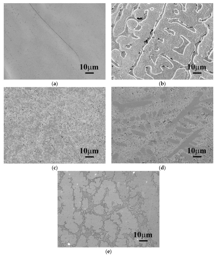
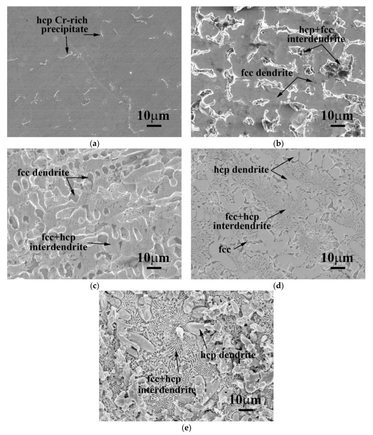
The as-cast SEM microstructures of CrFeCoNiNbx alloys are shown in Figure 1. Figure 1a shows the microstructure of as-cast CrFeCoNi alloy. The CrFeCoNi alloy had a granular microstructure with an average grain size of several hundred micrometers; some hcp-structured Cr-rich precipitates in the fcc matrix were reported in our previous study [12]. However, the microstructures of as-cast CrFeCoNiNbx alloys became a dendritic microstructure after adding niobium. The dendrites were a single phase, and the interdendrites showed a eutectic structure. The dendrites of these alloys had different morphologies after etching. The dendrites of CrFeCoNiNb0.2 and CrFeCoNiNb0.4 alloys had significant imprints after etching, as shown in Figure 1b,c, but those of CrFeCoNiNb0.6 and CrFeCoNiNb alloys exhibited almost smooth surfaces after etching, as shown in Figure 1d,e. These differences were caused by the different phases of the dendrites in these alloys. The dendrites of CrFeCoNiNb0.2 and CrFeCoNiNb0.4 alloys were an fcc phase, and the dendrites of CrFeCoNiNb0.6 and CrFeCoNiNb alloys were a Laves phase (hcp structure). The interdendrites of CrFeCoNiNbx alloys had two major phases which were fcc and hcp phases (Laves phase). These were identified and described below.
Figure 1.
The SEM microstructures of as-cast CrFeCoNiNbx alloys, (a) CrFeCoNi; (b) CrFeCoNiNb0.2; (c) CrFeCoNiNb0.4; (d) CrFeCoNiNb0.6; and (e) CrFeCoNiNb alloys.
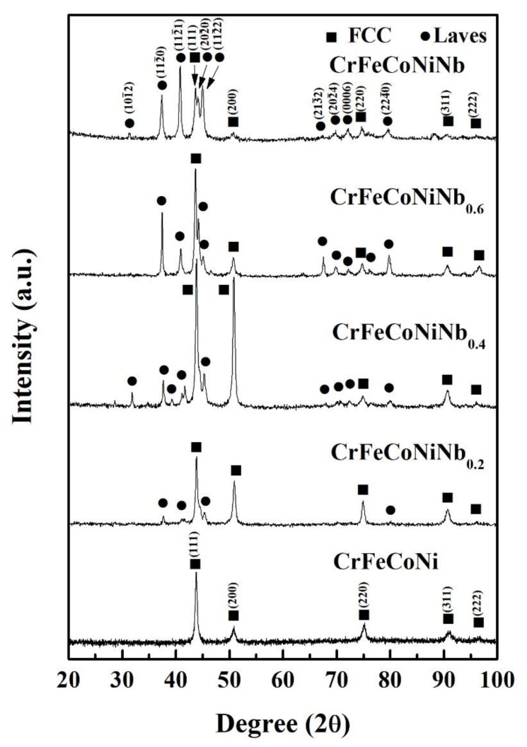
Figure 2 shows the XRD patterns of CrFeCoNiNbx alloys. There are two phases which existed in the CrFeCoNiNbx alloys, which are fcc and Laves phases. The intensities of Laves phases in the CrFeCoNiNbx alloys increase with increasing Nb-content. Table 2 lists the lattice constants of fcc and Laves phases analyzed from the XRD patterns. The lattice constants of fcc and Laves phases increased with increasing Nb-content in the CrFeCoNiNbx alloys. This result was caused by the larger atomic radius of niobium. The atomic radiuses of Cr, Fe, Co, Ni, and Nb are 0.128, 0.124, 0.125, 0.125, and 0.143 nm, respectively [18]. The radiuses of Cr, Fe, Co, and Ni are very close, but niobium has a much larger atomic radius. Therefore, the lattice constants of fcc and Laves phases increased when the solid-solution amount of Nb-content increased in these alloys.
Figure 2.
XRD patterns of CrFeCoNiNbx alloys.
Table 2.
Lattice constants of fcc and Laves phases in as-cast CrFeCoNiNbx alloys.
| Alloys | fcc (Å) | Laves Phase (hcp) (Å) |
|---|---|---|
| CrFeCoNi | 3.577 | N/A |
| CrFeCoNiNb0.2 | 3.578 | a = 4.773; c = 7.818 |
| CrFeCoNiNb0.4 | 3.581 | a = 4.773; c = 7.831 |
| CrFeCoNiNb0.6 | 3.590 | a = 4.798; c = 7.841 |
| CrFeCoNiNb | 3.590 | a = 4.802; c = 7.848 |
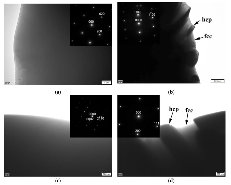
Figure 3 shows the TEM bright field (BF) images to examine the phases of the CrFrCoNiNbx alloys, and the inserts are their corresponding select area diffraction patterns (SADs). Figure 3a is an image of the dendrite of CrFrCoNiNb0.4 alloy. The corresponding SAD proves that the dendrite is an fcc phase. Figure 3b is an image of the interdendrite of CrFrCoNiNb0.4 alloy, and the corresponding SAD was taken from the Laves phase in the interdendrite. Figure 3c is an image of the dendrite of CrFrCoNiNb0.6 alloy. The corresponding SAD proves that the dendrite is a Laves phase (hcp structure). Figure 3d shows the image of the interdendrite of CrFrCoNiNb0.6 alloy, and the corresponding SAD was taken from the fcc phase in the interdendrite of CrFrCoNiNb0.6 alloy. Therefore, Figure 3 indicates that the CrFeCoNiNb0.4 alloy is a hypoeutectic alloy and that the dendrites of this alloy are an fcc phase; the CrFeCoNiNb0.6 alloy is a hypereutectic alloy, and the dendrites of the alloy are the Laves phase. In all of these alloys, the interdendrites are a dual-phased (fcc and Laves phase) eutectic structure. Chanda and Das [14] also pointed out that the Nb-content of eutectic CrFeCoNiNbx alloy should be located between 0.5 and 0.55.
Figure 3.
TEM bright field (BF) images and the corresponding selection area diffraction patterns (SAD) of CrFeCoNiNbx alloys: (a) the dendrite of CrFeCoNiNb0.4 alloy, and the corresponding SAD taken from [001] of fcc phase; (b) the Laves phase in the interdendrite of CrFeCoNiNb0.4 alloy, and the corresponding SAD taken from [43] of Laves phase; (c) the Laves phase in the dendrite of CrFeCoNiNb0.6 alloy, and the corresponding SAD taken from [010] of Laves phase; and (d) the fcc phase in the interdendrite of CrFeCoNiNb0.6 alloy, and the corresponding SAD taken from [011] of fcc phase.
Table 3 lists the chemical compositions of the CrFeCoNiNbx alloys which were analyzed by SEM/EDS. The fcc phase had higher Cr-, Fe-, Co-, and Ni-contents, but less Nb-content than the average compositions of the alloys. On the contrary, the Laves phase of CrFeCoNiNbx alloys had higher Nb-content and less Cr-, Fe-, Co-, and Ni-contents than the average.
Table 3.
Chemical compositions of the CrFeCoNiNbx alloys analyzed by SEM/EDS.
| Alloys | Compositions (Atomic Percent) | ||||
|---|---|---|---|---|---|
| Cr | Fe | Co | Ni | Nb | |
| CrFeCoNi | |||||
| Overall | 23.1 | 24.8 | 26.1 | 26.0 | N/A |
| Cr-rich precipitate | 53.8 | 16.1 | 15.9 | 14.2 | N/A |
| CrFeCoNiNb0.2 | |||||
| Overall | 23.4 | 23.5 | 23.3 | 22.3 | 7.4 |
| fcc | 24.2 | 26.5 | 24.3 | 23.2 | 1.8 |
| hcp | 19.4 | 18.2 | 23.1 | 21.2 | 18.1 |
| CrFeCoNiNb0.4 | |||||
| Overall | 22.7 | 21.6 | 22.3 | 21.6 | 11.8 |
| fcc | 25.2 | 24.3 | 22.2 | 24.9 | 3.5 |
| hcp | 21.3 | 19.3 | 19.8 | 19.1 | 20.5 |
| CrFeCoNiNb0.6 | |||||
| Overall | 21.4 | 20.6 | 21.5 | 19.3 | 17.2 |
| fcc | 25.1 | 24.4 | 21.8 | 23.0 | 5.7 |
| hcp | 16.5 | 18.4 | 22.3 | 15.9 | 26.9 |
| CrFeCoNiNb | |||||
| Overall | 19.8 | 19.8 | 19.0 | 19.4 | 22.0 |
| fcc | 26.7 | 24.3 | 18.4 | 25.5 | 5.1 |
| hcp | 17.1 | 18.1 | 19.7 | 14.8 | 30.3 |
| precipitate | 16.7 | 16.7 | 19.1 | 15.7 | 31.8 |
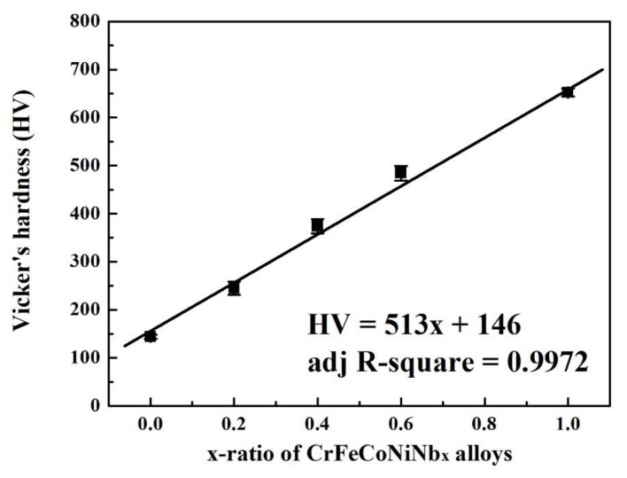
Figure 4 plots the overall hardness of CrFeCoNiNbx alloys as a function of x-ratio. The hardness of CrFeCoNiNbx alloys almost linearly increases with increasing Nb-content. The two phases, fcc and Laves phases, in these CrFeCoNiNbx alloys were two solid-solution phases, because no superlattice peak was observed from the XRD patterns and no superlattice spot was found from the TEM SADs of the CrFeCoNiNbx alloys. Therefore, the effect of solid-solution strengthening was caused by the larger-radius element Nb in the fcc and Laves phases.
Figure 4.
Plot of the overall hardness of CrFeCoNiNbx alloys as a function of x-ratio.
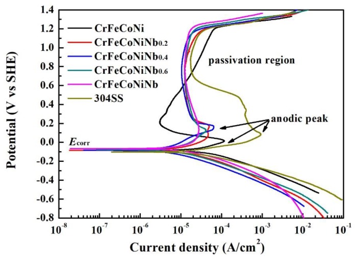
The polarization curves of CrFeCoNiNbx alloys and 304SS in 1 M deaerated H2SO4 solution are shown in Figure 5, and Table 4 lists the polarization data of the alloys. The values of free corrosion potential (Ecorr) of these alloys are close. Increasing the Nb-content of CrFeCoNiNbx alloys resulted in slightly increasing the Ecorr of the alloys. The free corrosion current density (icorr) varied randomly in these alloys, because the microstructures and the fractions of the phases in the alloys changed significantly. The CrFeCoNiNb0.6 alloy had the lowest icorr among these alloys. In addition, increasing the Nb-content of CrFeCoNiNbx alloys resulted in decreasing the anodic peaks of these alloys. The 304 stainless steel had the largest anodic peak among these alloys, and the CrFeCoNiNb alloy had the smallest anodic peak. The largest current density (icrit) and the potential (Epp) of the anodic peak of each alloy are listed in Table 4. Therefore, the CrFeCoNiNb alloy entered the passivation region more easily than the other alloy in this solution. Moreover, adding Nb could stabilize the passivation region of CrFeCoNiNbx alloys. The passivation regions of these alloys broke down at potentials of about 1.2 VSHE because of an oxygen evolution reaction [19]. All of the passivation regions of CrFeCoNiNbx alloys were broader than that of 304SS.
Figure 5.
Polarization curves of CrFeCoNiNbx alloys and 304SS in 1 M deaerated H2SO4 solution at 30 °C.
Table 4.
Polarization data of the alloys in 1 M deaerated H2SO4 solution at 30 °C.
| Alloys | Ecorr (VSHE) | icorr (A/cm2) | Epp (VSHE) | icrit (A/cm2) |
|---|---|---|---|---|
| CrFeCoNi | −0.086 | 35.1 | 0.014 | 120 |
| CrFeCoNiNb0.2 | −0.084 | 15.8 | 0.082 | 47.1 |
| CrFeCoNiNb0.4 | −0.082 | 52.1 | 0.183 | 64.4 |
| CrFeCoNiNb0.6 | −0.078 | 10.1 | 0.122 | 41.9 |
| CrFeCoNiNb | −0.068 | 22.3 | 0.132 | 28.0 |
| 304SS | −0.101 | 30.0 | 0.082 | 930 |
The morphologies of CrFeCoNiNbx alloys after polarization tests in 1 M deaerated H2SO4 solution at 30 °C are shown in Figure 6. The morphology of CrFeCoNi alloy indicated that it was uniformly and slightly corroded after the polarization test, as shown in Figure 6a. Figure 6b shows the micrograph of CrFeCoNiNb0.2 alloy after the test. The fcc-dendrites of CrFeCoNiNb0.2 alloy were concave, which meant that the dendrites were more severely corroded than the interdendrites. This implied that the fcc phase was more active than the hcp phase; the fcc phase thus preferred to be corroded more than the Laves phase. Figure 6c clearly indicates this phenomenon: The fcc dendrites of CrFeCoNiNb0.4 alloy were more severely corroded and almost vanished. However, the dendrites of CrFeCoNiNb0.6 alloy changed to the Laves phase, and the dendrites almost kept their original shapes; the matrix of interdendrites (fcc phase) was corroded after the polarization test, as shown in Figure 6d. The CrFeCoNiNb alloy also had a similar result, shown in Figure 6e.
Figure 6.
SEM micrographs of the alloys after polarization test in 1 M deaerated H2SO4 solution at 30 °C (a) CrFeCoNi; (b) CrFeCoNiNb0.2; (c) CrFeCoNiNb0.4; (d) CrFeCoNiNb0.6; and (e) CrFeCoNiNb alloys.
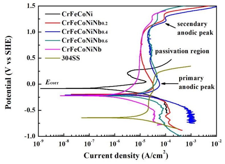
The polarization curves of CrFeCoNiNbx alloys and 304SS in 1 M deaerated NaCl solution are shown in Figure 7, and Table 5 lists the polarization data of the alloys. The values of Ecorr of CrFeCoNiNbx alloys were very close; they are nobler than that of 304SS, but more active than that of CrFeCoNi alloy. The values of icorr of CrFeCoNiNbx alloys were all higher than that of CrFeCoNi alloy. The icorr of CrFeCoNiNb0.6 alloy had the highest value. The CrFeCoNiNb0.2 and CrFeCoNiNb alloys had smaller icorr, and their values were almost the same as that of 304SS. The primary anodic peak of CrFeCoNi alloy was significant, but increasing the Nb-content of CrFeCoNiNbx alloys would diminish the anodic peaks of these alloys. Therefore, the CrFeCoNiNb alloy had no anodic peak. Moreover, adding Nb could expand the passivation regions of CrFeCoNiNbx alloys.
Figure 7.
Polarization curves of CrFeCoNiNbx alloys and 304SS in 1 M deaerated NaCl solution at 30 °C.
Table 5.
Polarization data of the alloys in 1 M deaerated NaCl solution at 30 °C.
| Alloys | Ecorr (VSHE) | icorr (μA/cm2) | Epp (VSHE) | icrit (μA/cm2) |
|---|---|---|---|---|
| CrFeCoNi | −0.081 | 0.28 | 0.049 | 17.3 |
| CrFeCoNiNb0.2 | −0.192 | 12.3 | −0.086 | 33.2 |
| CrFeCoNiNb0.4 | −0.207 | 21.1 | −0.006 | 58.1 |
| CrFeCoNiNb0.6 | −0.212 | 72.5 | 0.152 | 46.7 |
| CrFeCoNiNb | −0.221 | 12.0 | N/A | N/A |
| 304SS | −0.638 | 12.9 | N/A | N/A |
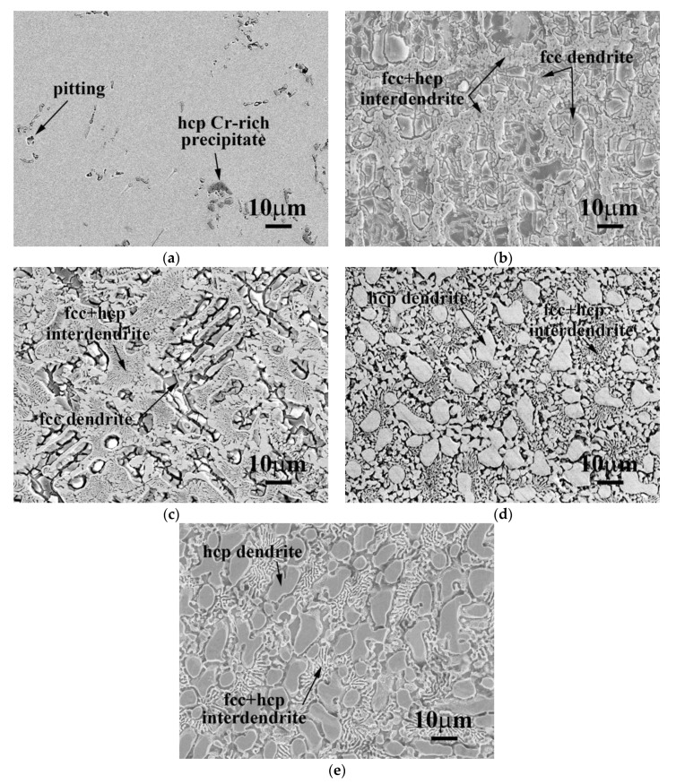
The morphologies of CrFeCoNiNbx alloys after polarization tests in 1 M deaerated NaCl solution at 30 °C are shown in Figure 8. The micrograph of CrFeCoNi alloy after the polarization test indicated that it was only slightly corroded, as shown in Figure 8a. However, the fcc dendrites of CrFeCoNiNb0.2 and CrFeCoNiNb0.4 alloys were severely corroded after the tests, as shown in Figure 8b,c. The dendrites (Laves phase) of CrFeCoNiNb0.6 and CrFeCoNiNb alloys almost kept their original shapes, but the matrices of the interdendrites (fcc phase) were corroded after the tests, shown in Figure 8d,e. Therefore, the fcc phase was more active than the Laves phase in the CrFeCoNiNbx alloys, and the fcc phase thus preferred to corrode more than Laves phase in 1 M deaerated H2SO4 and 1 M deaerated NaCl solutions.
Figure 8.
SEM micrographs of the alloys after polarization tests in 1 M deaerated NaCl solution at 30 °C (a) CrFeCoNi; (b) CrFeCoNiNb0.2; (c) CrFeCoNiNb0.4; (d) CrFeCoNiNb0.6; and (e) CrFeCoNiNb alloys.
4. Conclusions
The CrFeCoNi alloy had an fcc granular structure. The microstructures became dual-phased dendritic microstructures after adding niobium. The CrFeCoNiNb0.2 and CrFeCoNiNb0.4 alloys were hypereutectic alloys; their dendrites were fcc phases, and the interdendrites were eutectic structures of fcc and Laves phases (hcp). The CrFeCoNiNb0.6 and CrFeCoNiNb alloys were hypoeutectic alloys; their dendrites were a Laves phase, and the interdendrites were still eutectic structures of fcc and Laves phases.
The lattice constants of fcc and Laves phases in these CrFeCoNiNbx alloys increased with increasing Nb-content due to solid-solution strengthening. Increasing Nb-content also resulted in increasing the hardness of CrFeCoNiNbx alloys. The hardness increased from HV144 of CrFeCoNi alloy to HV652 of CrFeCoNiNb alloy.
The corrosion resistance of CrFeCoNiNbx alloys slightly decreased after adding niobium because of their dual-phased dendritic microstructures. In addition, adding niobium into CrFeCoNiNbx alloys could stabilize and expand the passivation regions of these alloys in these two solutions. The fcc phase of each CrFeCoNiNbx alloy was more severely corroded than the Laves phase after polarization tests in 1 M deaerated H2SO4 and 1 M deaerated NaCl solutions.
The CrFeCoNiNbx alloys possessed good corrosion resistance, and their hardness changed with Nb-content. This work thus provides a method to design a CrFeCoNiNbx alloy with suitable hardness and good corrosion resistance for different commercial applications.
Author Contributions
C.-H.T. conceived and designed the experiments; C.-Y.Y. and M.-C.T. performed the experiments; all of the authors analyzed the data; C.-Y.Y. and M.-C.T. contributed reagents/materials/analysis tools; C.-H.T. wrote the paper. All of the authors have read and approved the final manuscript.
Funding
We are grateful to the Ministry of Science and Technology of Republic of China for its financial support under the project MOST 106-2221-E-034-008.
Conflicts of Interest
The authors declare no conflict of interest. The funding sponsors had no role in the design of the study; in the collection, analyses, or interpretation of data; in the writing of the manuscript, and in the decision to publish the results.
References
- 1.Yeh J.W., Chen S.K., Lin S.J., Gan J.Y., Chin T.S., Shun T.T., Tsau C.H., Chang S.Y. Nanostructured high-entropy alloys with multiple principal elements: Novel alloy design concepts and outcomes. Adv. Eng. Mater. 2004;6:299–303. doi: 10.1002/adem.200300567. [DOI] [Google Scholar]
- 2.Murty B.S., Yeh J.W., Ranganathan S. High-Entropy Alloys. Butterworth-Heinemann Co.; London, UK: 2014. pp. 13–36. [Google Scholar]
- 3.George E.P., Raabe D., Ritchie R.O. High-entropy alloys. Nat. Rev. Mater. 2019;4:515–534. doi: 10.1038/s41578-019-0121-4. [DOI] [Google Scholar]
- 4.Gao M.C., Yeh J.W., Liaw P.K., Zhang Y. High-Entropy Alloys, Fundamentals and Applications. Springer; Berlin, Germany: 2016. pp. 1–19. [Google Scholar]
- 5.Tsai M.H., Yeh J.W. High-Entropy Alloys: A Critical Review. Mater. Res. Lett. 2014;2:107–123. doi: 10.1080/21663831.2014.912690. [DOI] [Google Scholar]
- 6.Chen S.T., Tang W.Y., Kuo Y.F., Chen S.Y., Tsau C.H., Shun T.T., Yeh J.W. Microstructure and properties of age-hardenable AlxCrFe1.5MnNi0.5 alloys. Mater. Sci. Eng. A. 2010;547:5818–5825. doi: 10.1016/j.msea.2010.05.052. [DOI] [Google Scholar]
- 7.Lee C.P., Chen Y.Y., Hsu C.Y., Yeh J.W., Shih H.C. Enhancing pitting corrosion resistance of AlxCrFe1.5MnNi0.5 high-entropy alloys by anodic treatment in sulfuric acid. Thin Solid Films. 2008;517:1301–1305. doi: 10.1016/j.tsf.2008.06.014. [DOI] [Google Scholar]
- 8.Mariano N.A., Souza C.A.C., May J.E., Kuri S.E. Influence of Nb content on the corrosion resistance and saturation magnetic density of FeCuNbSiB alloys. Mater. Sci. Eng. A. 2003;354:1–5. doi: 10.1016/S0921-5093(02)00032-1. [DOI] [Google Scholar]
- 9.Hsu Y.J., Chiang W.C., Wu J.K. Corrosion behavior of FeCoNiCrCux high-entropy alloys in 3.5% sodium chloride solution. Mater. Chem. Phys. 2005;92:112–117. doi: 10.1016/j.matchemphys.2005.01.001. [DOI] [Google Scholar]
- 10.Tsau C.H., Lee P.Y. Microstructures of Al7.5Cr22.5Fe35Mn20Ni15 High-Entropy Alloy and Its Polarization Behaviors in Sulfuric Acid, Nitric Acid and Hydrochloric Acid Solutions. Entropy. 2016;18:288. doi: 10.3390/e18080288. [DOI] [Google Scholar]
- 11.Lin C.M., Tsai H.L. Evolution of microstructure, hardness, and corrosion properties of high-entropy Al0.5CoCrFeNi alloy. Intermetallics. 2011;19:288–294. doi: 10.1016/j.intermet.2010.10.008. [DOI] [Google Scholar]
- 12.Tsau C.H., Lin S.X., Fang C.H. Microstructures and corrosion behaviors of FeCoNi and CrFeCoNi equimolar alloys. Mater. Chem. Phys. 2017;186:534–540. doi: 10.1016/j.matchemphys.2016.11.033. [DOI] [Google Scholar]
- 13.Tsau C.H., Tsai M.C. The effects of Mo and Nb on the microstructures and properties of CrFeCoNi(Nb,Mo) alloys. Entropy. 2018;20:648. doi: 10.3390/e20090648. [DOI] [PMC free article] [PubMed] [Google Scholar]
- 14.Chanda B., Das J. Composition Dependence on the Evolution of Nanoeutectic in CoCrFeNiNbx (0.45≤x≤0.65) High Entropy Alloys. Adv. Eng. Mater. 2017;1700908:1–9. [Google Scholar]
- 15.Jiang H., Han K., Li D., Cao Z. Microstructure and Mechanical Properties Investigation of the CoCrFeNiNbx High Entropy Alloy Coatings. Crystals. 2018;8:409. doi: 10.3390/cryst8110409. [DOI] [Google Scholar]
- 16.Zhang M., Zhang L., Liaw P.K., Li G. Effect of Nb content on thermal stability, mechanical and corrosion behaviors of hypoeutectic CoCrFeNiNbχ high-entropy alloys. J. Mater. Res. 2018;33:3276–3286. doi: 10.1557/jmr.2018.103. [DOI] [Google Scholar]
- 17.Revie R.W., Uhlig H.H. Corrosion and Corrosion Control. 4th ed. John Wiley & Sons Co.; Hoboken, NJ, USA: 2008. pp. 31–63. [Google Scholar]
- 18.Smith W.F. Foundations of Materials Science and Engineering. 3rd ed. McGraw-Hill Co.; New York, NY, USA: 2004. pp. 877–878. [Google Scholar]
- 19.Callister W.D., Jr. Fundamentals of Materials Science and Engineering: An Integrated Approach. 2nd ed. John Wiley & Sons, Inc.; New York, NY, USA: 2005. p. 674. [Google Scholar]


