Abstract
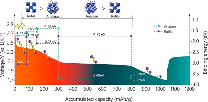
The shuttling effect of polysulfides species seriously deteriorates the performance of Li–S batteries, representing the major obstacle for their practical use. However, the exploration of ideal cathodes that can suppress the shuttling of all polysulfides species is challenging. Herein, we propose an ingenious and effective strategy for constructing hybrid-crystal-phase TiO2/covalent organic framework (HCPT@COF) composites where hybrid anatase/rutile TiO2 nanodots (10 nm) are uniformly embedded in the interlayers of porous COFs. The synthesis was realized via a multiple-step reaction relay accompanying by a pseudo-topotactic transformation of three-dimensional layered structures from 1,4-dicyanobenzene monomer-embedded Ti-intermediate networks to HCPT nanodots-embedded COF frameworks. The HCPT@COF/S cathodes show superior comprehensive performance such as high specific capacity, long cycling stability, and remarkable rate capability for Li–S batteries, owing to the complementary anchoring effect of hybrid anatase/rutile TiO2 in the HCPT@COF composite, which is evidenced by substantial characterizations including X-ray photoelectron spectroscopy and density functional theory calculations.
Short abstract
A hybrid anatase/rutile nanodots-embedded covalent organic framework composite as a Li−S battery anode shows superior performance due to its complementary chemical binding effect toward polysulfides species.
Introduction
Lithium–sulfur (Li–S) batteries have been considered as a promising alternative for conventional lithium-ion batteries, due to their low cost and natural abundance. Moreover, sulfur possesses an impressive theoretical capacity with a specific energy that is higher than that of the state-of-the-art lithium-ion batteries.1,2 However, the practical application of Li–S batteries is greatly hindered by their low sulfur utilization, poor long-term cyclability, and inferior rate capability caused mainly by the sluggish ion diffusion/reaction kinetics and especially a series of side effects upon the dissolution and the “shuttle effect” due to the migration of lithium polysulfide (LiPS) intermediates (Li2Sn, 2 ≤ n ≤ 8) in electrolytes.3−5 Therefore, an effective solution to the above problems is highly desired for Li–S batteries to promote their practical application.
A variety of approaches have been developed to address the aforementioned issues. Most commonly, carbon materials such as porous carbons6,7 and carbon nanotubes8 were employed as homogenous sulfur hosts to accommodate sulfur molecules and facilitate Li+ ion diffusion when used in electrodes.9 Nonetheless, Li–S batteries based on mere carbon materials often experienced dramatic capacity decay due to sulfur loss caused by the weak interactions between polar LiPSs and nonpolar carbon host materials.10 To obtain stronger interactions such as chemical bonding with the LiPSs, functional heterologous host materials were further developed by addressing polar metal oxides additives such as SiO2,11 TiO2,12 Al2O3,13 and La2O314 or their derivatives of TiC,15 TiO2–TiN,16 and TiS2/VS2.17 However, these functional heterogenous sulfur host materials reported previously were often realized by physically mixing/depositing polar additives with/on presynthesized carbon materials, which not only suffered from complicated processes, but would result in a weak interaction between the two components and a bad dispersion of polar additives. In particular, most heterogenous host materials contained a single polar additive whose chemical bonding effect may be only effective to one or fewer LiPS species, leading to insufficient trapping of polysulfides.
Recently, covalent organic frameworks (COFs),18−20 a kind of layered structured material with a controllable pore size and highly ordered pore arrangement first proposed in 2005,20 have attracted considerable attention in catalysis21−23 and especially lithium–sulfur batteries.24−26 The large specific surface area with the easy-to-form ordered porous structure of COFs enables high sulfur loadings, effective alleviation of sulfur volume expansion, and fast ions diffusion. However, similar to that based on other carbon materials, Li–S batteries using pure COFs as sulfur host materials showed poor cycling performance and rate capability.
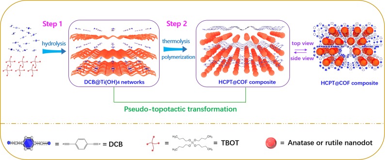
Herein, we propose an ingenious and effective strategy for the synthesis of hybrid-crystal-phase TiO2/COF (HCPT/COF) composites, where hybrid anatase/rutile TiO2 nanodots (10 nm) are uniformly embedded in the interlayers of the porous COF. The synthesis is realized through a multiple-reaction relay involving the hydrolysis of Ti precursor to form Ti intermediate (Ti(OH)4) (Scheme 1, step 1), followed by the synchronous thermolysis of Ti(OH)4 and the polymerization of 1,4-dicyanobenzene (DCB) monomers into COF with molten ZnCl2 as a solvent and catalyst (Scheme 1, step 2). The synthetic process is accompanied by the pseudo-topotactic transformation of three-dimensional (3D) layered structures from DCB monomer-embedded Ti(OH)4 networks to hybrid-crystal TiO2 nanodots-embedded COF frameworks (step 2). The prepared HCPT@COF composite holds a high specific surface area of 809 m2 g–1 and a large pore volume of 0.87 cm3 g–1. X-ray photoelectron spectroscopy (XPS) reveals that N–Ti interfacial bonds are formed between TiO2 nanodots and COFs induced by the oxygen vacancy in HCPT nanodots, which strengthen the HCPT nanodots-embedded COF frameworks and provide an efficient electron transfer channel. Density functional theory (DFT) calculations imply that the hybrid TiO2 shows a complementary chemical anchoring effect toward LiPS species. As a result, the HCPT@COF/S electrodes demonstrate a superior electrochemical performance for Li–S batteries, including a high reversible capacity (1149 mAh g–1 at 0.5 C), outstanding cycling stability (800 cycles at 0.5 C with a low capacity decay rate of 0.030% per cycle), and remarkable rate capability (a ∼63.7% retention upon 20 times variation from 0.2 to 4 C).
Scheme 1. Schematic Illustration for the Construction of Hybrid Anatase/Rutile Nanodots-Embedded COF Composites via a Pseudo-topotactic Transformation Enabled by a Multiple-Reaction Relay.
Results and Discussion
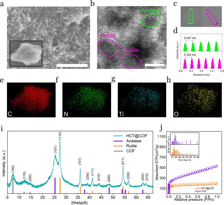
The as-prepared HCPT@COF composite was ground into powder before characterization. A low-magnification scanning electron microscopy (SEM) image (Figure 1a) shows that the HCPT@COF composite holds an irregular shape (inset in Figure 1a) with TiO2 nanodots uniformly dispersed on the COF porous framework, which is mirrored in the corresponding transmission electron microscopy (TEM) images (Figure S1a,b). For the HCPT@COF composite, the layered structure of COF is not observed, different from that of bare COF (Figure S1c,d), which is due to the existence of TiO2 nanodots in the interlayers of COF. In a high-magnification TEM image (Figure 1b), several nanoparticles with an average size of 10 nm are observed in the COF framework, showing clear crystal lattices corresponding to anatase TiO2 and rutile TiO2 (Figure 1c,d), respectively. Specifically, the d-spacing of 0.346 nm is assigned to the (101) plane of anatase TiO2 (JCPDS 21-1272), and 0.324 nm corresponds to the (110) plane of the rutile crystal (JCPDS 21-1276). The result validates the coexistence of anatase and rutile TiO2 nanodots in the COF framework. The corresponding element mappings of C, N, Ti, and O (Figure 1e) suggest that these elements distribute uniformly throughout the framework, revealing the HCPT nanodots are well dispersed in the COF framework. The X-ray diffraction (XRD) pattern in Figure 1i reveals a set of reflections corresponding to a hybrid crystal phase of anatase and rutile crystals in the HCPT@COF composite. It is noted that the (001) peak corresponding to the interlayers of the COF almost disappears, consistent with the TEM observation that the interlayers of the COF are invisible, which is different from the bare COF (Figure S2) and the previous report.27 The XRD pattern of TiO2@COF composites synthesized at higher temperatures (Figure S3) reveals that the contents of anatase TiO2 are decreased at 500 °C and completely disappeared at 700 °C. In addition, the (100) and (110) peaks of COF remain for the composite prepared at 500 °C, while almost disappear for the composite at 700 °C, resulting from the irreversible carbonization of COF at higher temperatures.18 Further preparation experiments of HCPT@COF composites below 400 °C were not conducted, as the catalytic polymerization reaction of DCB monomers forming COF occurred above 400 °C.18 It is noted that the ratios of rutile to anatase for the composites prepared at temperatures of the typical 400 °C (denoted as HCPT@COF-400) and 500 °C (denoted as TiO2@COF-500) are roughly estimated to be 19.1:80.9 and 39.6:60.4 (w/w), respectively (Figure S4).
Figure 1.
(a) SEM image of the HCPT@COF composite. Inset shows the selected bulk composite for element mapping characterization. (b–d) TEM image of the HCPT@COF composite and selected areas of anatase and rutile phase showing crystal lattice distance in (c) and (d). (e–h) Selected area element maps. (i) XRD pattern of the HCPT@COF composite. (j) N2 adsorption–desorption isotherm curves of the HCPT@COF composite and bare COF. Inset in (j) shows the pore size distribution of the HCPT@COF composite and bare COF.
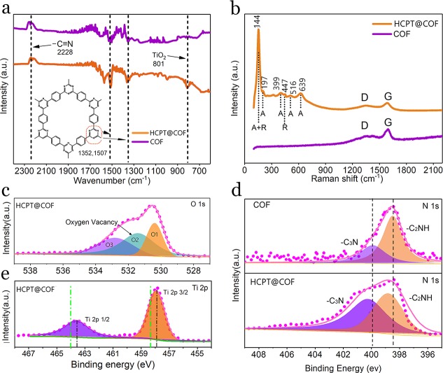
The Brunauer–Emmett–Teller (BET) measurement shows that the typical HCPT@COF composite and the bare COF possess a specific surface area of 809 m2 g–1 and 943 m2 g–1, respectively (Figure 1j). Notably, the average size of the micropores is expanded to 1.71 nm, approximately 14% wider than the bare COF with a theoretically calculated pore width of triazine cycling (1.5 nm)28 (inset diagrams). Furthermore, the pore volume of the typical HCPT@COF composite is 0.87 cm3 g–1, which is beneficial for sulfur infiltration and buffering the volume fluctuation while functioning as a Li–S battery composite electrode. The BET results and pore structure information on the TiO2@COF composites synthesized at different temperatures are shown in Figure S5 and Table S1. It is found in Table S1 that the composites prepared at higher temperatures possess higher specific surface area values, due to the occurrence of carbonization of COF22 and the coalescence of TiO2 nanodots at higher temperatures, which generate more pores in the COF frameworks with an increased specific surface area of the composites. The trimerization reaction of the DCB monomers responsible for COF formation in the HCPT@COF composite is further characterized by Fourier transform infrared spectrometer (FTIR) measurements (Figure 2a). The disappearance of the otherwise intensive carbonitrile band at 2228 cm–1 indicates the successful trimerization reaction. The two main strong absorption bands at 1352 and 1507 cm–1 correspond to the formation of triazine rings.18 Compared with the bare COF, the HCPT@COF composite shows an extra absorption band at 801 cm–1, proving the existence of TiO2 nanodots.29 The Raman spectrum of the HCPT@COF composite in Figure 2b shows a sharp peak at 144 cm–1 corresponding to both the Eg mode in anatase and the B1g mode in rutile. The spectrum also exhibits a peak at 447 cm–1 assigned to the Eg mode in rutile,30 while anatase is identified by the shoulder at 197 cm–1 (Eg), and the peaks at 399 (B1g), 516 cm–1 (A1g), and 639 cm–1 (Eg).31
Figure 2.
(a) FTIR spectra of the HCPT@COF composite and the bare COF. (b) Raman spectra of the HCPT@COF composite and the bare COF. (c) O 1s XPS spectrum of the HCPT@COF composite. (d) N 1s XPS spectra of the HCPT@COF composite and the bare COF. (e) Ti 2p XPS spectrum of the HCPT@COF composite. Green vertical dotted lines in (e) correspond to the Ti 2p binding energy of normal pure-phase TiO2 without any heteroatom doped or other phase combined.
X-ray photoelectron spectroscopy (XPS) was further conducted to evaluate the valence state of the elements and the interaction between COF and TiO2 components in the composite. Contents of C, N, Ti, and O elements are determined to be in a mass ratio of 75:10.4:5:9.4 (Table S2), consistent with the original stoichiometry of the reactants. In addition, the mass ratio of TiO2 in the typical HCPT@COF composite is calculated to be 15 wt % using XPS results. O1s XPS spectrum (Figure 2c) is deconvoluted into three peaks at 530.6, 531.5, and 532.9 eV, attributed to Ti–O bonds, oxygen defect sites in TiO2, and hydroxy species of surface absorbed water molecules, respectively. The N1s spectra of the bare COF and the HCPT@COF composite in Figure 2d can be deconvoluted into two peaks of -C2NH (398–399 eV) and -C3N (400–401 eV).22 Notably, both peaks in the composite shift left toward higher energy values, indicating that a lower electron density and electron-lacking state of N atoms, compared with the bare COF. Moreover, Ti2p peaks in the HCPT@COF composite (Figure 2e) show binding energy that is ∼0.4 eV lower than the normal-TiO2 (∼464 eV, marked as green vertical dotted lines),32 suggesting the strong interaction between the triazine rings and hybrid TiO2 via interfacial N–Ti bonds.33,34 However, for TiO2@COF composites synthesized at higher temperatures of 500 and 700 °C, the XPS measurements imply a weakened interaction of N–Ti bonds between the two components of COF and TiO2, induced by the reduction of oxygen defects in the composites (Figure S6).
To further evaluate the electrochemical properties of the HCPT@COF toward the application of Li–S batteries, sulfur was thermally impregnated into host materials using a facile dispersing and thermal diffusion strategy to fabricate the composite cathodes. The existence of S in the composite is evidenced by the corresponding XPS spectra before and after infiltration (Figure S7). Element maps indicate that S is infiltrated into the pores of COF and uniformly dispersed in the composite (Figure S8). The initial mass loading of S in the typical HCPT@COF/S and the COF/S samples is measured to be 69.3% and 70.1%, respectively, based on the thermogravimetric analysis (TGA) (Figure S9).
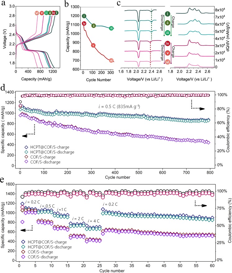
The as-prepared composite cells were cycled under the voltage range of 1.7–2.8 V (versus Li/Li+). Figure 3a shows the galvanostatic profiles of the HCPT@COF/S and COF/S composites at 0.2 C from 1st, 100th, and 300th cycle, respectively. Both the composite electrodes display two typical well-defined plateaus at ∼2.4 and ∼2.1 V, corresponding to the multistep reduction reactions in cathodes during the discharge process. The high plateaus at ∼2.4 V are ascribed to the transformation from the octasulfur to long-chain LiPSs (Li2Sn, 4 ≤ n ≤ 8), while low and relatively long plateaus at ∼2.1 V are ascribed to the reduction of long-chain LiPSs to short-chain LiPSs (Li2S2 or Li2S).35 The charge/discharge profiles show considerable changes in the anodic and cathodic overpotentials. The HCPT@COF/S composite electrode delivers an initial discharge capacity of 1224 mAh g–1 along with discharge capacities of 1117 and 1053 mAh g–1 at 0.2 C at the 100th and 300th cycle, respectively (Figure 3b). In comparison, the COF/S electrode exhibits an initial discharge capacity of 1208 mAh g–1 and a respective discharge capacity of 820 and 694 mAh g–1 at the 100th and 300th cycle, showing fast capacity degradation. To further investigate the LiPSs anchoring effect inside the composite on the battery performance, dQ/dV versus potential plots for the above-mentioned cycles were constructed, as shown in Figure 3c. Two peaks of dQ/dV at ∼2.1 and ∼2.4 V respectively correspond to the two discharge plateaus, which are considered to contribute the dominant discharge capacity in sulfur reduction reactions. For the HCPT@COF/S electrode, the intensity of the dominant peak (∼2.1 V) retains at a level of 82% at the 300th cycle compared with the first cycle, whereas the peak intensity for the COF/S electrode decreases dramatically to 58% at the 300th cycle, suggesting a severe shuttle effect in the COF/S electrode causing the fast capacity decay. For the second peak appearing at ∼2.4 V, the HCPT@COF/S electrode displays a notable positive potential shift compared to that of the COF/S electrode, which indicates a smaller polarization and a faster electrochemical reaction proceeded on the surface of the HCPT@COF/S than on the COF/S.15 dQ/dV vs potential plots for the charge profiles show three main peaks corresponding to the redox reactions for the short-chain LiPSs transforming to the long-chain LiPSs and finally to the octasulfur. Notably, the central peak for the COF/S electrode at ∼2.3 V fades upon cycling and disappears at the 300th cycle, suggesting a higher energy barrier as well as a more serious polysulfide dissolution and shuttle effect during the charging process. Electrochemical impedance spectra (EIS) results also indicate that the HCPT@COF/S (HCPT@COF-400/S) electrode exhibits a better charge transfer capability and electrochemical kinetics than the COF/S electrode, as well as the electrodes based on the TiO2@COF-500 and TiO2@COF-700 composites (Figure S10 and Table S3). Figure 3d displays the long cycling performance of the HCPT@COF/S and COF/S electrodes at 0.5 C. For the HCPT@COF/S electrode, an initial charge of 1149 mAh g–1 and a discharge capacity of 1036 mAh g–1 are delivered, respectively. The initial Coulombic efficiency reaches as high as 90.2%, followed by the continually high efficiency of nearly 100% during the 800 cycles, indicating that the shuttle effect has been greatly suppressed in the HCPT@COF/S composite electrode. After 800 cycles, the electrode still achieves a reversible capacity of 875 mAh g–1, giving a high capacity retention of 76.2% with a low capacity decay of 0.030% per cycle. In contrast, the COF/S cathode shows a rapid capacity fading with a final discharge capacity of 487.6 mAh g–1 after 500 cycles. Moreover, the HCPT@COF/S electrode also exhibits outstanding rate capability. As shown in Figure 3e, when the cell was operated at 0.2, 0.5, 1.0, and 2.0 C, the electrode delivered a high reversible capacity of 1061, 1031, 928, and 740 mAh g–1 (calculated based on the third cycle of each current density). Even at a very high rate of 4 C, the reversible capacity of ∼676 mAh g–1 can still be retained, yielding a high retention of ∼63.7%. When the current density returns to 0.2 C, the discharge capacity rebounds to 996 mAh g–1 without dramatic capacity degradation for more than 30 cycles at this rate. The cycling and rate performance tests were also conducted for the TiO2@COF composites synthesized at higher temperatures and compared to that of the typical HCPT@COF/S and COF/S electrodes, as shown in Figures S11 and S12. For practical applications, long cyclability at a high rate is a key factor for Li–S batteries.36−38 In this regard, the long-term test up to 1500 cycles at 3 C was conducted for the HCPT@COF-400/S electrode, and a low capacity fading ratio of 0.029% per cycle is obtained after cycling (Figure S13). It is found that the TiO2-based composite electrodes show better performance than the COF/S electrode, which is ascribed to the enhanced polar adsorption between S and TiO2 in the TiO2/COF cathodes via S–Ti bonds (Figure S14). For the TiO2-based composite electrodes, the typical HCPT@COF/S electrode demonstrates the best performance among the three. It is noted that the HCPT@COF composite possesses the lowest specific surface area and the smallest pore volume that are disadvantageous to the performance of Li–S batteries. Therefore, the significant performance improvement of the HCPT@COF/S electrode is due to the best adsorption effect of hybrid crystal TiO2 toward LiPSs (Figure S15).
Figure 3.
(a) Voltage profiles of the HCPT@COF/S composite electrode (blue curves) and the COF/S composite electrode (red curves) in the 1st cycle (i and iv), 100th cycle (ii and v), and 300th cycle (iii and vi) at 0.2 C, respectively. (b) Specific capacity comparison of the HCPT@COF/S electrode (blue curve) and the COF/S electrode (red curve) at 0.2 C at the 1st, 100th, and 300th cycle, respectively. (c) Plots of differential capacity of the HCPT@COF/S electrode (blue curves) and the COF/S electrode (red curves) in the first cycle (i and iv), 100th cycle (ii and v), and 300th cycle (iii and vi). (d) Long cycling performance of the HCPT@COF/S and COF/S electrodes at 0.5 C. (e) Rate performance of the HCPT@COF/S and COF/S electrodes followed by a cycling performance of 0.2 C. The above synthesis temperature of COF is 400 °C.
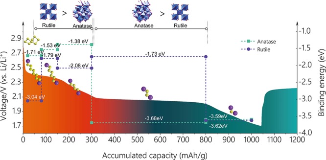
To better understand the interaction between the hybrid-crystal TiO2 and LiPSs, density functional theory calculations were carried out on a series of representative LiPS species to further elucidate the underlying mechanism during the discharge process for the HCPT@COF composite electrode. The surfaces in (101) plane of anatase and in (110) plane of rutile were chosen for calculations since they behaved as the most stable structures.39 A symmetrical model was built to correct the dipole, and adsorption was allowed on only one side of the exposed surfaces (only the top three-layer atoms of TiO2 were fully relaxed). For quantitatively measuring the interaction between the surface and adsorbates of Li2S, Li2S2, Li2S4, Li2S6, and Li2S8, we define the binding energy Eb as follows: Eb = Etotal – (Esur + Eads), where Esur, Eads, and Etotal represent the total energies of the surface, the Li2Sx (x = 1, 2, 4, 6, and 8) cluster, and the adsorption pair of the substrate and a certain cluster, respectively. The simulation results are shown in Scheme 2, showing the binding energy of rutile and anatase with different LiPSs produced in the discharge process from 1.7–2.8 V. The results indicate that long-chain LiPS species (Li2S8, Li2S6, Li2S4) show higher binding energies with the rutile-TiO2 (110) surface (3.04, 1.79, and 2.08 eV) than those with the anatase-TiO2 (101) surface (1.71, 1.53, and 1.38 eV), respectively, while the short-chain LiPS (Li2S2) shows much lower binding energy with rutile-TiO2 (1.73 eV) than with anatase (3.68 eV). The final product Li2S shows almost the same binding energy with both the anatase-TiO2 (3.59 eV) and rutile-TiO2 surface (3.62 eV). COF containing N atoms was reported to show an adsorption effect on LiPSs by the Li–N interactions.24 However, compared with the strong interaction of TiO2 with LiPSs via Ti and S atoms, the interaction effect between Li and N atoms from COF is much weak. The capacity related to long-chain LiPSs (Li2S8, Li2S6, Li2S4) dominated by the adsorption of rutile is ∼300 mAh g–1 and the short-chain LiPS (Li2S2) dominated by the adsorption of anatase is ∼500 mAh g–1, which respectively contributes a high percentage of 28.6% and 47.6% to the total capacity. The results above demonstrate that hybrid anatase and rutile show a complementary adsorption effect on LiPS species and function more predominantly than their single phase during the discharge process.
Scheme 2. Schematic Diagram Showing the Binding Energy of Rutile and Anatase TiO2 with a Series of Li–S Discharge Products Corresponding to Multiple Reaction Stages.
Safety Statement
No unexpected or unusually high safety hazards were encountered.
Conclusion
In summary, the HCPT@COF composites have been constructed through a pseudo-topotactic transformation of 3D layered networks enabled by a multireaction relay. The elaborately designed strategy allows the uniform distribution of HCPT nanodots in porous COF frameworks and strong interaction (Ti–N bonds) between HCPT nanodots and COF frameworks. The HCPT@COF composite with unique structural advantages showed superior comprehensive performance for Li–S batteries as a sulfur host material, such as high capacity uptake, superior cycling stability, and remarkable rate capability. The DFT calculations reveal that the hybrid phase of rutile and anatase respectively shows a synergistic adsorption effect on the LiPSs species to effectively suppress the shuttle effect. This study provides a new strategy to develop layered composite materials favorable for high-performance Li–S batteries and energy applications.
Acknowledgments
This work was financially supported by National Natural Science Foundation (51972235, 21875141), Natural Science Foundation of Shanghai (17ZR1447800), the Program for Professor of Special Appointment (Eastern Scholar) at Shanghai Institutions of Higher Learning, Hundred Youth Talent Plan of Tongji University, Shanghai Pujiang Program (18PJ1409000), the Opening Project of State Key Laboratory of Advanced Chemical Power Sources (SKL-ACPS-C-23), and the Fundamental Research Funds for the Central Universities.
Supporting Information Available
The Supporting Information is available free of charge on the ACS Publications website at DOI: 10.1021/acscentsci.9b00846.
Experimental details, characterizations of TEM images, XRD patterns, BET analyses, XPS spectra, and performance tests including Nyquist plots, cycling performance, rate performance, performance comparison, and DFT calculations of the HCPT@COF composites and bare COF (PDF)
Author Contributions
∇ Z.Y., C.P., and R.M. contributed equally.
The authors declare no competing financial interest.
Supplementary Material
References
- Eftekhari A. Lithium batteries for electric vehicles: from economy to research strategy. ACS Sustainable Chem. Eng. 2019, 7, 3684–3687. 10.1021/acssuschemeng.7b04330. [DOI] [Google Scholar]
- Tan G.; Xu R.; Xing Z.; Yuan Y.; Lu J.; Wen J.; Liu C.; Ma L.; Zhan C.; Liu Q.; Wu T.; Jian Z.; Shahbazian-Yassar R.; Ren Y.; Miller D. J.; Curtiss L. A.; Ji X.; Amine K. Burning lithium in CS2 for high-performing compact Li2S–graphene nanocapsules for Li–S batteries. Nat. Energy 2017, 2, 17090. 10.1038/nenergy.2017.90. [DOI] [Google Scholar]
- Evers S.; Nazar L. F. New Approaches for high energy density lithium–sulfur battery cathodes. Acc. Chem. Res. 2013, 46, 1135–1143. 10.1021/ar3001348. [DOI] [PubMed] [Google Scholar]
- Bresser D.; Passerini S.; Scrosati B. Recent progress and remaining challenges in sulfur-based lithium secondary batteries. Chem. Commun. 2013, 49, 10545–10562. 10.1039/c3cc46131a. [DOI] [PubMed] [Google Scholar]
- Manthiram A.; Fu Y.; Su Y. S. Challenges and prospects of lithium–sulfur batteries. Acc. Chem. Res. 2013, 46, 1125–1134. 10.1021/ar300179v. [DOI] [PubMed] [Google Scholar]
- Ji X.; Lee K. T.; Nazar L. F. A highly ordered nanostructured carbon–sulphur cathode for lithium–sulphur batteries. Nat. Mater. 2009, 8, 500–506. 10.1038/nmat2460. [DOI] [PubMed] [Google Scholar]
- Schuster J.; He G.; Mandlmeier B.; Yim T.; Lee K. T.; Bein T.; Nazar L. F. Spherical ordered mesoporous carbon nanoparticles with high porosity for lithium–sulfur batteries. Angew. Chem., Int. Ed. 2012, 51, 3591–3595. 10.1002/anie.201107817. [DOI] [PubMed] [Google Scholar]
- Chen S.; Sun B.; Xie X.; Mondal A. K.; Huang X.; Wang G. Multi-chambered micro/mesoporous carbon nanocubes as new polysulfides reserviors for lithium–sulfur batteries with long cycle life. Nano Energy 2015, 16, 268–280. 10.1016/j.nanoen.2015.05.034. [DOI] [Google Scholar]
- Wang D. W.; Zeng Q.; Zhou G.; Yin L.; Li F.; Cheng H. M.; Gentle I. R.; Lu G. Q. M. Carbon–sulfur composites for Li–S batteries: status and prospects. J. Mater. Chem. A 2013, 1, 9382–9394. 10.1039/c3ta11045a. [DOI] [Google Scholar]
- Pang Q.; Kundu D.; Cuisinier M.; Nazar L. F. Surface-enhanced redox chemistry of polysulphides on a metallic and polar host for lithium-sulphur batteries. Nat. Commun. 2014, 5, 4759. 10.1038/ncomms5759. [DOI] [PubMed] [Google Scholar]
- Ji X.; Evers S.; Black R.; Nazar L. F. Stabilizing lithium–sulphur cathodes using polysulphide reservoirs. Nat. Commun. 2011, 2, 325. 10.1038/ncomms1293. [DOI] [PubMed] [Google Scholar]
- Evers S.; Yim T.; Nazar L. F. Understanding the nature of absorption/adsorption in nanoporous polysulfide sorbents for the Li–S battery. J. Phys. Chem. C 2012, 116, 19653–19658. 10.1021/jp304380j. [DOI] [Google Scholar]
- Dong K.; Wang S.; Zhang H.; Wu Preparation and electrochemical performance of sulfur-alumina cathode material for lithium-sulfur batteries. Mater. Res. Bull. 2013, 48, 2079–2082. 10.1016/j.materresbull.2013.02.031. [DOI] [Google Scholar]
- Sun F.; Wang J.; Long D.; Qiao W.; Ling L.; Lv C.; Cai R. A high-rate lithium–sulfur battery assisted by nitrogen-enriched mesoporous carbons decorated with ultrafine La2O3 nanoparticles. J. Mater. Chem. A 2013, 1, 13283–13289. 10.1039/c3ta12846f. [DOI] [Google Scholar]
- Peng H. J.; Zhang G.; Chen X.; Zhang Z. W.; Xu W. T.; Huang J. Q.; Zhang Q. Enhanced electrochemical kinetics on conductive polar mediators for lithium–sulfur batteries. Angew. Chem., Int. Ed. 2016, 55, 12990–12995. 10.1002/anie.201605676. [DOI] [PubMed] [Google Scholar]
- Zhou T.; Lv W.; Li J.; Zhou G.; Zhao Y.; Fan S.; Liu B.; Li B.; Kang F.; Yang Q. H. Twinborn TiO2–TiN heterostructures enabling smooth trapping–diffusion–conversion of polysulfides towards ultralong life lithium–sulfur batteries. Energy Environ. Sci. 2017, 10, 1694–1703. 10.1039/C7EE01430A. [DOI] [Google Scholar]
- Seh Z. W.; Yu J. H.; Li W.; Hsu P. C.; Wang H.; Sun Y.; Yao H.; Zhang Q.; Cui Y. Two-dimensional layered transition metal disulphides for effective encapsulation of high-capacity lithium sulphide cathodes. Nat. Commun. 2014, 5, 5017. 10.1038/ncomms6017. [DOI] [PubMed] [Google Scholar]
- Kuhn P.; Antonietti M.; Thomas A. Porous, Covalent triazine-based frameworks prepared by ionothermal synthesis. Angew. Chem., Int. Ed. 2008, 47, 3450–3453. 10.1002/anie.200705710. [DOI] [PubMed] [Google Scholar]
- Kuhn P.; Forget A.; Su D.; Thomas A.; Antonietti M. From microporous regular frameworks to mesoporous materials with ultrahigh surface area: dynamic reorganization of porous polymer networks. J. Am. Chem. Soc. 2008, 130, 13333–13337. 10.1021/ja803708s. [DOI] [PubMed] [Google Scholar]
- Cote A. P.; Benin A. I.; Ockwig N. W.; O’keeffe M.; Matzger A. J.; Yaghi O. M. Porous, crystalline, covalent organic frameworks. Science 2005, 310, 1166–1170. 10.1126/science.1120411. [DOI] [PubMed] [Google Scholar]
- Chan-Thaw C. E.; Villa A.; Prati L.; Thomas A. Triazine-based polymers as nanostructured supports for the liquid-phase oxidation of alcohols. Chem. - Eur. J. 2011, 17, 1052–1057. 10.1002/chem.201000675. [DOI] [PubMed] [Google Scholar]
- Kamiya K.; Kamai R.; Hashimoto K.; Nakanishi S. Platinum-modified covalent triazine frameworks hybridized with carbon nanoparticles as methanol-tolerant oxygen reduction electrocatalysts. Nat. Commun. 2014, 5, 5040. 10.1038/ncomms6040. [DOI] [PMC free article] [PubMed] [Google Scholar]
- Kamai R.; Kamiya K.; Hashimoto K.; Nakanishi S. Oxygen tolerant electrodes with platinum loaded covalent triazine frameworks for the hydrogen oxidation reaction. Angew. Chem., Int. Ed. 2016, 55, 13184–13188. 10.1002/anie.201607741. [DOI] [PubMed] [Google Scholar]
- Ghazi Z. A.; Zhu L.; Wang H.; Naeem A.; Khattak A. M.; Liang B.; Khan N. A.; Wei Z.; Li L.; Tang Z. Efficient polysulfide chemisorption in covalent organic frameworks for high-performance lithium-sulfur batteries. Adv. Energy Mater. 2016, 6, 1601250. 10.1002/aenm.201601250. [DOI] [Google Scholar]
- Yoo J.; Cho S. J.; Jung G. Y.; Kim S. H.; Choi K. H.; Kim J. H.; Lee C. K.; Kwak S. K.; Lee S. Y. COF-net on CNT-net as a molecularly designed, hierarchical porous chemical trap for polysulfides in lithium–sulfur batteries. Nano Lett. 2016, 16, 3292–3300. 10.1021/acs.nanolett.6b00870. [DOI] [PubMed] [Google Scholar]
- Je S. H.; Kim H. J.; Kim J.; Choi J. W.; Coskun A. Perfluoroaryl-elemental sulfur snar chemistry in covalent triazine frameworks with high sulfur contents for lithium–sulfur batteries. Adv. Funct. Mater. 2017, 27, 1703947. 10.1002/adfm.201703947. [DOI] [Google Scholar]
- Kuhn P.; Thomas A.; Antonietti M. Toward tailorable porous organic polymer networks: a high-temperature dynamic polymerization scheme based on aromatic nitriles. Macromolecules 2009, 42, 319–326. 10.1021/ma802322j. [DOI] [Google Scholar]
- Thomas A.; Kuhn P.; Weber J.; Titirici M. M.; Antonietti M. Porous polymers: enabling solutions for energy application. Macromol. Rapid Commun. 2009, 30, 221–236. 10.1002/marc.200800642. [DOI] [PubMed] [Google Scholar]
- Liu Z.; Jian Z.; Fang J.; Xu X.; Zhu X.; Wu S. Low-temperature reverse microemulsion synthesis, characterization, and photocatalytic performance of nanocrystalline titanium dioxide. Int. J. Photoenergy 2012, 2012, 1. 10.1155/2012/702503. [DOI] [Google Scholar]
- Porto S.; Fleury P.; Damen T. Raman spectra of TiO2, MgF2, ZnF2, FeF2, and MnF2. Phys. Rev. 1967, 154, 522–526. 10.1103/PhysRev.154.522. [DOI] [Google Scholar]
- Ohsaka T.; Izumi F.; Fujiki Y. Raman spectrum of anatase, TiO2. J. Raman Spectrosc. 1978, 7, 321–324. 10.1002/jrs.1250070606. [DOI] [Google Scholar]
- Zeng Q. G.; Ding Z. J.; Zhang Z. M. Synthesis, structure and optical properties of Eu3+/TiO2 nanocrystals at room temperature. J. Lumin. 2006, 118, 301–307. 10.1016/j.jlumin.2005.09.002. [DOI] [Google Scholar]
- Du X.; Wang Y.; Mu Y.; Gui L.; Wang P.; Tang Y. A new highly selective H2 sensor based on TiO2/PtO–Pt dual-layer films. Chem. Mater. 2002, 14, 3953–3957. 10.1021/cm0201293. [DOI] [Google Scholar]
- Yang J.; Bai H.; Tan X.; Lian J. IR and XPS investigation of visible-light photocatalysis—Nitrogen–carbon-doped TiO2 film. Appl. Surf. Sci. 2006, 253, 1988–1994. 10.1016/j.apsusc.2006.03.078. [DOI] [Google Scholar]
- Wild M.; O’Neill L.; Zhang T.; Purkayastha R.; Minton G.; Marinescu M.; Offer G. J. Lithium sulfur batteries, a mechanistic review. Energy Environ. Sci. 2015, 8, 3477–3494. 10.1039/C5EE01388G. [DOI] [Google Scholar]
- Li Y.; Xu P.; Chen G.; Mou J.; Xue S.; Li K.; Zheng F.; Dong Q.; Hu J.; Yang C.; Liu M. Enhancing Li-S redox kinetics by fabrication of a three dimensional Co/CoP@ nitrogen-doped carbon electrocatalyst. Chem. Eng. J. 2020, 380, 122595. 10.1016/j.cej.2019.122595. [DOI] [Google Scholar]
- Tang H.; Li W.; Pan L.; Tu K.; Du F.; Qiu T.; Yang J.; Cullen C.; McEvoy N.; Zhang C. A robust, freestanding MXene-sulfur conductive paper for long-lifetime Li–S batteries. Adv. Funct. Mater. 2019, 29, 1901907. 10.1002/adfm.201901907. [DOI] [Google Scholar]
- He J.; Chen Y.; Manthiram A. Vertical Co9S8 hollow nanowall arrays grown on a celgard separator as a multifunctional polysulfide barrier for high-performance Li–S batteries. Energy Environ. Sci. 2018, 11, 2560–2568. 10.1039/C8EE00893K. [DOI] [Google Scholar]
- Yu M.; Ma J.; Song H.; Wang A.; Tian F.; Wang Y.; Qiu H.; Wang R. Atomic layer deposited TiO2 on a nitrogen-doped graphene/sulfur electrode for high performance lithium–sulfur batteries. Energy Environ. Sci. 2016, 9, 1495–1503. 10.1039/C5EE03902A. [DOI] [Google Scholar]
Associated Data
This section collects any data citations, data availability statements, or supplementary materials included in this article.


